Pro DVX IPPC-15-6000 User manual

0
User Guide
IPPC-15-6000
IPPC-22-6000
Comfort

Table of Contents
1. Unpacking………..……....……………………………………………………………............1
1.1 General instructions...……...………………………………………………....……….…1
1.2 Package content…...……………………………………………………………………..1
2. Physical view and features
2.1 Front view IPPC-15-6000…………………………………………………………………2
2.2 Rear view IPPC-15-6000.………………………………………………………..………..2
2.3 I/O ports and buttons IPPC-15-6000 bottom…………………………………………...3
2.4 I/O ports and buttons IPPC-15-6000 side + adapter…………………………………...3
2.5 I/O ports and buttons IPPC-15-6000 back side………………………………………...4
2.6 Front view IPPC-22-6000…………………………………………………………………5
2.7 Rear view IPPC-22-6000…………………………………………………………………. 5
2.8 I/O ports and buttons IPPC-22-6000 bottom………………………………………….. 6
2.9 I/O ports and buttons IPPC-22-6000 adapter…………………………………………. 6
2.10 I/O ports and buttons IPPC-22-6000 back side……………………………………….7
3. Powering on the product…………………………………………………………….... 8
4. Product functionality…………………………………………………….........................9
5. Support and cleaning……………………………..…………………………..………….11
5.1 Support……………………………..……………..……………………………………… 11
5.2 Cleaning……………………………..…………………….……………………………… 12
6. Technical specifications……………..……………………………………....................13
7. Pixel defect policy……………..…………………….……………………………………..14
7.1 Pixels and sub-pixels……………..…………………….………………………………...14
7.2 Types of pixel defects + dot definition……………..………………………………...…14
7.3 Bright dot defects……………..…………………….…………………………………… 15
7.4 Dark dot defects……………..…………………….……………………….……………. 15
7.5 Pixel defect tolerances……………..…………………….……………………….……...15
7.6 Mura……………..…………………….…………………………….……………………..16
8. Warranty……………..…………………………….……………………………………..……17
9. Safety instructions……………..……………………………….……………...…………18
10. Declaration and statements ……………..…………………………………....…..20
10.1 EU Declaration of Conformity pixels and sub-pixels……………..………….………..20
10.2 FCC Declaration of Conformity (U.S. only) ……………..………………….…………..20
10.3 Waste Electrical and Electronic Equipment-WEEE……………..………….………….21
10.4 Software end user license agreement……………..…………..…………….…………22

1
1. Unpacking
1.1 General instructions
This electronic user guide is intended for all ProDVX product users. Take time to read it before you
use your product. It contains important information and notes regarding the use of your product.
The ProDVX guarantee applies provided the product is handled properly for its intended use, in
accordance with its operating instructions and upon presentation of the original invoice or cash
receipt, indicating the date of purchase, dealers name and model and the product production
number. Please read and follow the safety precautions and maintenance instructions starting on
page 18 when connecting and using your display.
1.2 Package content
Verify that the box contains:
•ProDVX IPPC-15/22-6000 device
•Power adapter
•Region specific power cable
•Quick Start Guide
Preliminary steps:
•Please remove all protective materials from the device.
•Inspect the device for damage.
•Contact ProDVX if there is damage or something is missing.
2
2. Physical view and features
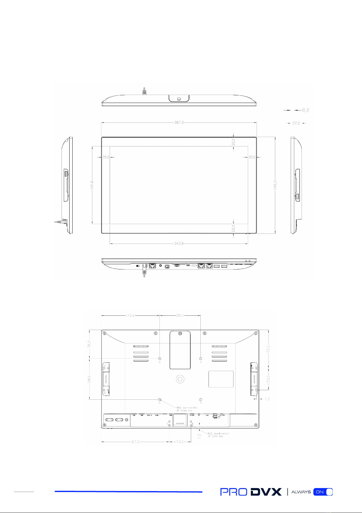
2.1 Front view IPPC-15-6000
2.2 Rear view IPPC-15-6000

3
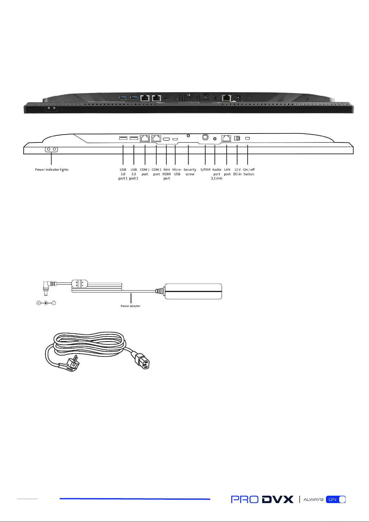
2.3 I/O ports and buttons IPPC-15-6000 bottom
2.4 I/O ports and buttons IPPC-15-6000 side + adapter

4
2.5 I/O ports and buttons IPPC-15-6000 back side
5
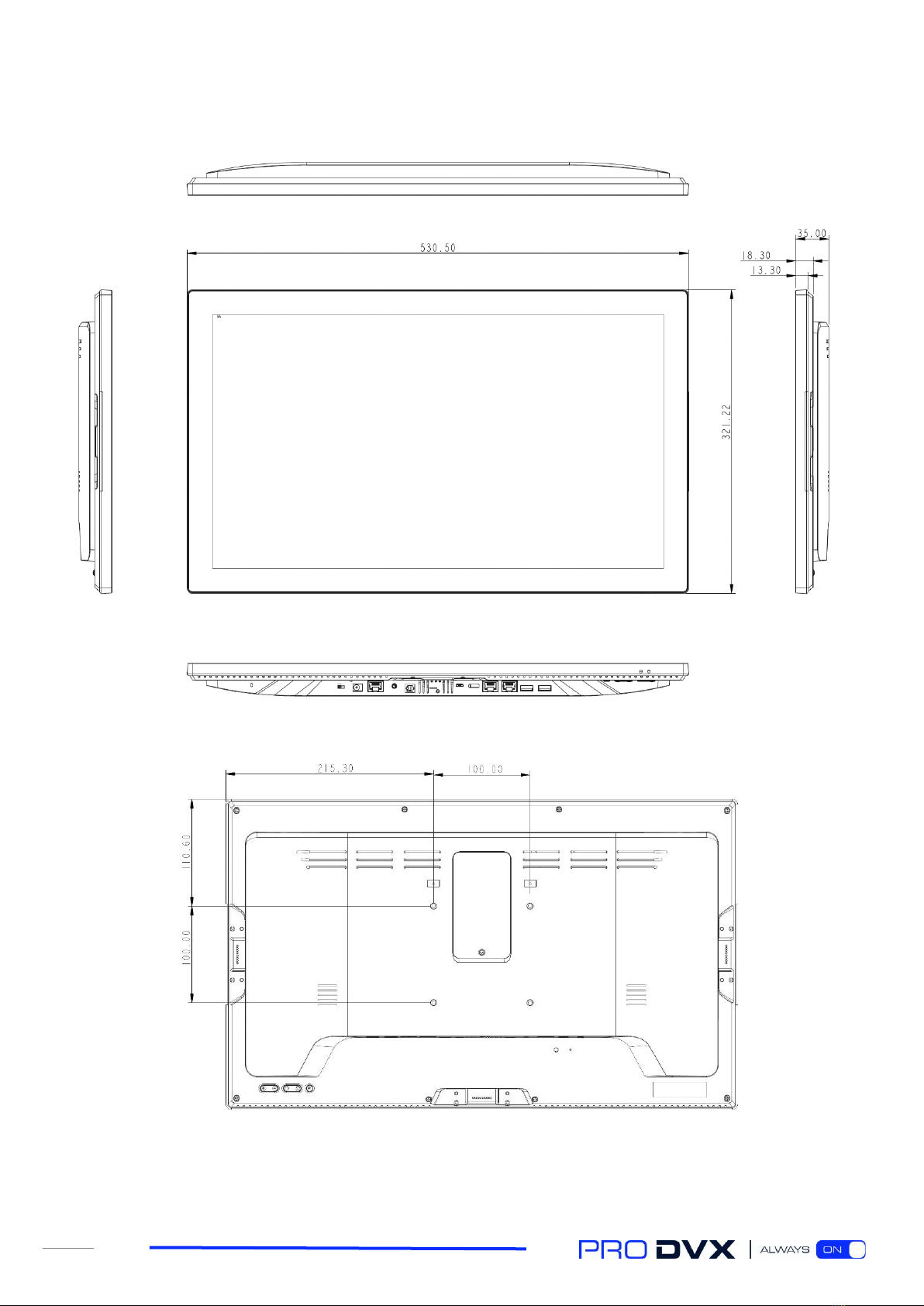
2.6 Front view IPPC-22-6000
2.7 Rear view IPPC-22-6000
6
2.8 I/O ports and buttons IPPC-22-6000 bottom
2.9 I/O ports and buttons IPPC-22-6000 adapter

7
2.10 I/O ports and buttons IPPC-22-6000 back side
S

8
3. Powering on the product
STEP 1 –Power ON
When connecting the power adapter to the mains and the display, switching the on/off switch will
power on the device.
STEP 2 –OS (de)installation
We have preinstalled a version of Microsoft Windows Enterprise 10 LTSC as a service, including all
relevant drivers, because that is the most commonly used operating system on the IPPC-15-6000
and IPPC-22-6000 models. It is also possible to remove this operating system and replace it with
one of your choice (e.g. Linux or a different Windows version). Please bear in mind that the device
doesn’t come with a Microsoft Windows 10 license. These are obtained separately.
STEP 3 –User account
After fully booting the device, it is recommended to create a new user ID, elevate the user access
level to administrator and delete the default (demo) user. By doing so, you have the possibility of
disabling/enabling certain Windows features. For a full overview of Microsoft Windows 10
configuration settings, please refer to the documentation from Microsoft.
STEP 4 –Windows update
It is likely that not all Windows updates are downloaded and installed because of an overlap in
production date and the new release of Windows updates. To be able to guarantee proper Windows
functionality, we suggest you fully update the device with all available Windows updates before you
start configuring the device and install the desired applications.

9
4. Product functionality
The IPPC-15-6000 and IPPC-22-6000 are fitted with several connectivity options.
VESA mount holes
These devices are fitted with a 100x100 mm VESA pattern. Please mount the device according to the
documentation provided with the mount. Take extra care with the screws: please use screws with a
length of 4 mm, up to 8 mm (minus the thickness of the mount). Longer screws might damage the
device internals. Please do not over-tighten the screws as this will damage the device internals.
USB port slot / SIM card slot (with cover)
Beneath the small door in the back cover you will find a USB 2.0 port and a SIM card slot capable of
containing one regular-sized SIM card. The IPPC-15-6000 and the IPPC-22-6000 have the option of
embedding a 4G/LTE module (mPCIe). To enable a 4G/LTE connection, the mobile operator requires
a SIM card to be connected to the module. Please refer to the 4G/LTE module documentation for
further details.
Pogo pin connector (USB-2.0)
The devices are fitted with 3 Pogo pin connectors on which devices like our external NFC reader,
1D/2D bar code scanner or camera can be securely connected.
Function keys
The devices have a set of function keys on the back side of the display. The function keys consist of
2 volume buttons, 2 buttons to increase/decrease brightness and one button which lets you mute
the audio coming from the device’s internal speakers.
On / off switch
This button can be used to switch the device on or off. You can change the behavior of this button in
the Windows settings.
LAN port / Wi-Fi / Bluetooth
The device has a 10/100/1000 Mbps LAN (RJ45) connection.
Next to the Ethernet port, the device has an embedded wireless LAN module (802.11 b/g/n/ac) that
supports Bluetooth 4.2
Audio port
This port can be used to connect a headphone, including a microphone. Please note that when
plugged in, the internal speakers are disabled.
10
S/PDIF
This is the digital audio port using a Toslink cable interface.
Micro-USB
The Micro-USB port can be used as a regular USB 2.0 port.
HDMI-out port
The device has a mini HDMI connector for connecting an external display to the device. Please note
this is an HDMI-out port only.
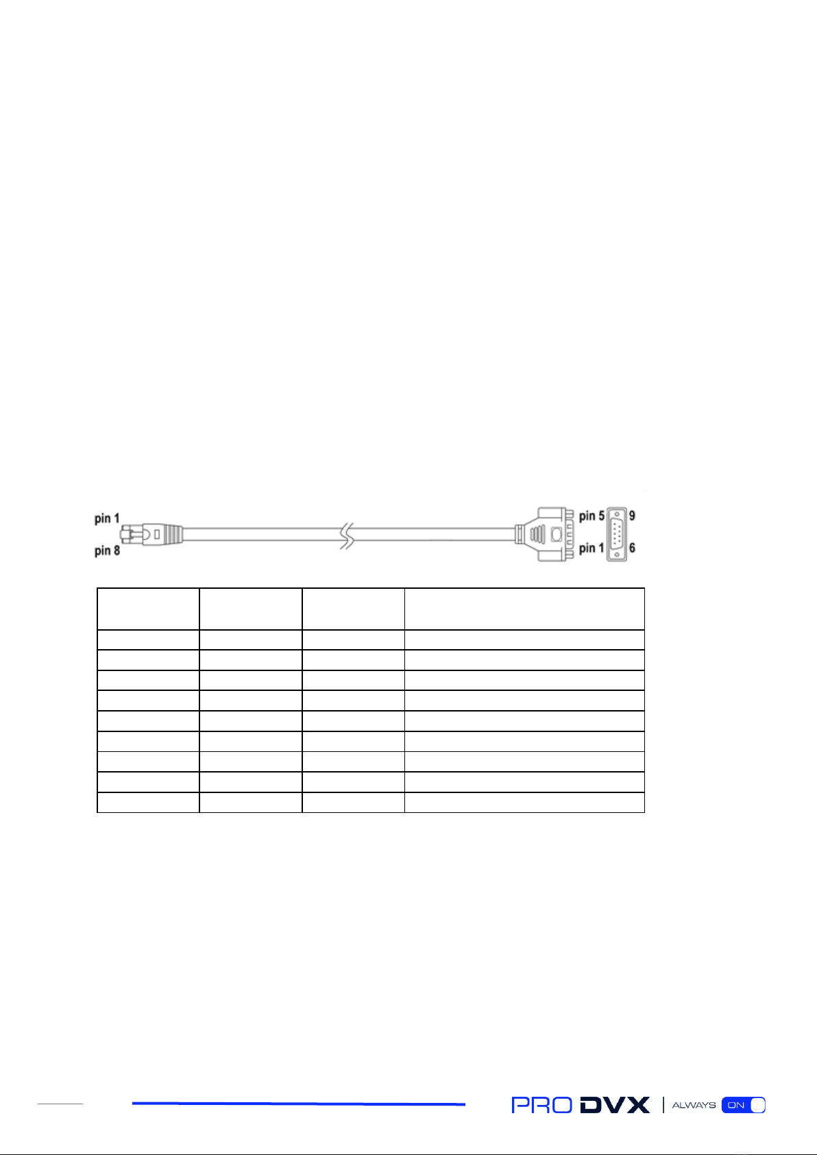
COM ports
The devices have two COM ports in the I/O section. These can be used for RS232 communication.
Two RJ45 to DB9 (male) converter cables are provided.
RJ45
Color
DB9 (male)
Function
1
CD (Carrier Detect)
6
Green
2
RxD (Receive Data)
3
Red
3
TxD (Transmit Data)
2
Brown
4
DTR (Data Terminal Ready)
4
Orange
5
GND (Ground)
7
Blue
6
DSR (Data Set Ready)
1
Black
7
RTS (Request to Send)
8
Purple
8
CTS (Clear to Send)
5
Yellow
9
RI (Ring indicator)
USB 3.0
This is a high-speed USB version 3.0 port, suitable for high speed connection with external
peripherals, such as USB storage devices, webcams, etc.
LED indicators
The LED indicators show the power status of the display. When red, the display is powered, but
turned off. When flashing in green, the display is in stand-by mode. When green, the display is on.

11
5. Support and cleaning
5.1 Support
Symptom
Possible cause
Possible remedy
I have no
connection
1. Is a network cable inserted?
1. Insert the cable. Make sure to insert it into the
correct connector.
2. Is the device connected to a Wi-
Fi network?
2. Connect the device to a Wi-Fi network.
3. Are the drivers installed?
3. If not, contact ProDVX support.
I have no sound
1. Is the sound level correct?
1. Use the volume buttons to adjust the level.
2. Are the headphones connected?
2. Disconnect the headphones to enable the
internal speakers.
3. Are the drivers installed?
3. If not, contact ProDVX support.
I have no display
1. Is the device switched off?
1. Press the small power switch on the device.
2. Is the PSU connected?
2. Connect the PSU.
My USB stick isn’t
recognized
1. Is the USB stick properly
formatted?
1. Format the USB stick in NTFS file format.
2. Is the USB stick properly
inserted?
2. Disconnect the USB stick and reconnect it to the
USB port.
My display is not
correct
1. Has the resolution been altered?
1. Increase or decrease the resolution setting.

12
5.2 Cleaning
Caution When Using the Monitor
•Be sure to disconnect all cables before moving the monitor. Moving the monitor with the
cables attached may damage the cables and cause fire or electrocution.
•Disconnect the power plug from the wall outlet as a safety precaution before performing
any type of cleaning or maintenance procedure.
Front Panel Cleaning Instructions
•The front of the display has been specially treated. Wipe the surface gently using only a
cleaning cloth or a soft, lint-free cloth.
•If the surface becomes dirty, soak a soft, lint-free cloth in a mild detergent solution. Wring
the cloth to remove excess liquid. Wipe the surface of the display to remove dirt. Then use a
dry cloth of the same type to dry it.
•Do not scratch or hit the surface of the panel with fingers or hard objects of any kind.
•Do not use volatile substances such as insert sprays, solvents or thinners.

13
6. Technical specifications
Panel
System
Size
Resolution
Brightness
Viewing Angle
Touch Type
Contract Ratio
Aspect Ratio
15.6”, 22.1”
1920x1080
250 cd/m2
H 160 ° / V 160 °
10 point touch projected
capacitive
3000:1
16:9 wide
CPU
GPU
System Memory
Internal Storage
OS (optional)
Network LAN RJ45
Wi-Fi
Bluetooth
Intel® Pentium N4200
Intel® HD Graphics
505
8GB DDR3L SDRAM
64GB M.2 Flash
Windows 10 LTSC
(optional Linux)
10/100/1000 Mbps
LAN
802.11 b/g/n/ac
BT 4.2
Physical
Other
Housing
Color
Weight
Dimensions
Mounting / VESA
Power Supply
Plastic
Black
1400 g (15”), 4200 g (22”)
388 x 242 x 28 mm (15”),
531 x 322 x 35 mm (22”)
VESA 100
12 V / 5 A (EU, UK, US)
I/O Ports
Audio Jack output
Speakers
USB3.0x2, USB2.0x3,
MicroUSB2.0x1, HDMI
type C, 3.5mm Audio-
out, RJ45, COM port
RJ45x2, 12V DC-in
Yes
2 x 2 W

14
7. Pixel defect policy
We make every effort to deliver the highest quality products and use some of the industry’s most
advanced manufacturing processes whilst practicing stringent quality control. However, pixel or
sub-pixel defects on the panels used in LCD displays are sometimes unavoidable. No manufacturer
can guarantee that all panels will be free of pixel defects, but ProDVX guarantees that any LCD
display with an unacceptable number of defects will be repaired during the warranty period in line
with your local guarantee conditions.
This notice explains the different types of pixel defects and defines the acceptable defect level for
the LCD screen. In order to qualify for repair under warranty, the number of pixel defects must
exceed a certain level as shown in the reference table. If the LCD screen is within specification, a
warranty exchange/claim back will be refused. Additionally, given that certain types or
combinations of pixel defects are more noticeable than others, ProDVX sets even higher quality
standards for these.
7.1 Pixels and sub-pixels
A pixel, or picture element, is composed of three sub-pixels in the primary
colors red, green and blue. Many pixels together form an image. When all the
sub-pixels of a pixel are lit, the three colored sub-pixels together appear as a
single white pixel. When they are all dark, the three colored sub-pixels together
appear as a single black pixel. Other combinations of lit and dark sub-pixels
appear as single pixels of other colors.
7.2 Types of pixel defects + dot definition
Pixel and sub-pixel defects appear on the screen in different ways. There are three categories of
pixel defects and several types of sub-pixel defects within each category.
Dot definition = what is a defective “dot”? :
One or more defective, adjacent sub-pixels are defined as one “dot”. The number of defective sub-
pixels is not relevant to define a defective dot. This means that a defective dot may consist of one,
two or three defective sub-pixels which may be dark or lit.
One dot = one pixel; consists of three red, green and blue sub-pixels.

15
7.3 Bright dot defects
Bright dot defects appear as pixels or sub-pixels that are always lit or “on”. These are the examples
of bright dot defects:
One lit red, green or blue Two adjacent lit sub pixels: Three adjacent lit sub pixels
sub pixel red + blue = purple (one white pixel)
red + green = yellow
green + blue = cyan
7.4 Dark dot defects
Black dot defects appear as pixels or sub-pixels that are always dark or “off”. These are the
examples of black dot defects:
One dark dot Two adjacent dark dots Two dark dots
(1 pair of dark dots)
7.5 Pixel defect tolerances
In order to qualify for repair due to pixel defects during the warranty period, an LCD display must
have pixel or sub-pixel defects exceeding the tolerances listed in the following table.
Bright dot effect:
Acceptable level
1 lit sub pixel
1
Black dot effect:
Acceptable level
1 dark subpixel
3
Total dot defects* of all types:
1
NOTE: * 1 - 3 adjacent sub pixel defects = 1 dot defect

16
7.6 Mura
Dark spots or patches may occasionally appear on some liquid crystal display (LCD) panels. This is
known in the industry as Mura, a Japanese term for “unevenness.” It is used to describe an
irregular pattern or area in which uneven screen uniformity appears under certain conditions. Mura
is a result of the deterioration of the liquid crystal alignment layer and is most commonly caused
by long-term operation under high ambient temperatures. It is an industry- wide phenomenon and
Mura is not repairable. It is also not covered by our warranty terms.
Mura has been around since the introduction of LCD technology and with screens getting bigger
and in operation 24/7, many displays run in low light conditions. This all adds to the possibility of
Mura affecting displays.
How to detect Mura
There are many symptoms of Mura and also multiple causes. Several of these are listed below:
•Impurities or foreign particles in the crystal matrix
•Uneven distribution of LCD matrix during manufacturing
•Non-uniform luminance distribution of the backlight
•Panel assembly induced stress
•Flaws within the LCD cell
•Thermal induced stress - high temperature operation over long periods of time
How to avoid Mura
Although we cannot guarantee the complete eradication of Mura every time, in general the
appearance of Mura can be minimized by these methods:
•Lower the backlight brightness
•Use a screensaver
•Reduce the ambient temperature around the unit

18
9. Safety instructions
Safety precautions and maintenance
This electronic user guide is intended for all ProDVX product users. Take time to read it before you
use your product. It contains important information and notes regarding the use of your product.
The ProDVX guarantee applies provided the product is handled properly for its intended use, in
accordance with its operating instructions and upon presentation of the original invoice or cash
receipt, indicating the date of purchase, dealer’s name, and model and product production
number.
WARNING: Use of controls, adjustments or procedures other than those specified in
this documentation may result in exposure to shock, electrical hazards and/or
mechanical hazards.
Read and follow these instructions when connecting and using your display:
Operation
•Keep the display out of direct sunlight and away from stoves or any other heat sources.
•Remove any object that could fall into ventilation holes or prevent the proper cooling of
the display’s electronics.
•Do not block the ventilation holes on the cabinet.
•When positioning the display, make sure the power plug and outlet are easily accessible.
•When turning off the display by detaching the power cord or DC power cord, wait 6 seconds
before re-attaching the power cord or DC power cord for normal operation.
•We strongly recommend you use a proper “shut-down” command instead of disconnecting
the display from the power source, to prevent potential damage to the internal systems
•Ensure the use of an approved power cord provided by ProDVX at all times. If your power
cord is missing, please contact your local service center.
•Do not expose the display to severe vibration or high impact conditions during operation.
•Do not knock or drop the display during operation or transportation.
Maintenance
•To protect your display from possible damage, do not put excessive pressure on the LCD
panel. When moving your display, grasp the frame to lift it; do not lift the display by placing
your hand or fingers on the LCD panel.
•Unplug the display if you are not going to use it for a long period of time.
•Unplug the display if you need to clean it with a slightly damp cloth. The screen may be
wiped with a dry cloth when the power is off. However, never use organic solvents such as
alcohol, or ammonia-based liquids to clean your display.
•To avoid the risk of shock or permanent damage to the set, do not expose the display to
dust, rain, water or an excessively moist environment.
•If your display becomes wet, wipe it with dry cloth as soon as possible.
•If a foreign substance or water enters your display, turn the power off immediately and
disconnect the power cord. Then remove the foreign substance or water and send the unit
to the maintenance center.
•Do not store or use the display in locations exposed to heat, direct sunlight or extreme
cold.
Other manuals for IPPC-15-6000
1
This manual suits for next models
1
Table of contents
Other Pro DVX Tablet Accessories manuals


