Pro-face GLC2500-TC41-200V User manual

When Designing your GLC System:
- Be sure to design your GLC control system so that in the event of
a main power supply failure or a GLC accident, the user system’s
overall safety integrity will be maintained. If this is not done, in-
correct output signals or a GLC malfunction may cause an acci-
dent.
(1) Interlock circuits, etc. designed to interrupt or oppose normal
machine movement (i.e. Emergency Stop, General Protection,
forward and reverse rotation, etc.), as well as those designed
to prevent machine damage (i.e. for upper, lower and traverse
movement limit positioning, etc.) should all be designed to be
located outside of the GLC.
(2) Whenever the GLC generates a “Watchdog Timer Error”, GLC
operation will halt. Also, when errors occur in Input/Output
control areas that the GLC cannot detect, it is possible for
unexpected movement to occur in those areas. As a result,
for the purpose of preventing unsafe machine movement, a
“Failsafe Circuit” should be created which is completely ex-
ternal to the GLC.
(3) If a problem arises with an external unit’s relay or transistor,
causing an output (coil) to remain either ON or OFF, a major
accident can occur. To prevent this, be sure to set up external
watchdog circuits that will monitor vital output signals.
- Be sure to design a circuit that will supply power to the GLC’s I/O
unit before starting up the GLC. If the GLC’s internal program
enters RUN mode prior to the I/O unit’s load control power turn-
ing ON, an incorrect output (signal) or malfunction could cause
an accident to occur.
- Be sure to design a program that will ensure the safety of the
user’s system, in the event of a GLC display or control error, or in
the event of either a data transmission error or power failure be-
tween the GLC and a connected unit. These types of problems
can lead to an incorrect output (signal) or malfunction, which could
thereby cause an accident to occur.
- Do not create GLC touch panel switches that could possibly en-
danger the safety of equipment and personnel. Damage to the
GLC, its I/O unit(s), cable(s), and other related equipment can
DANGERS
Industrial automation
Elincom Group
EuropeanUnion: www.elinco.eu
Russia: www.elinc.ru

-16-
- Do not use the GLC unit as a warning device for critical alarms
that can cause serious operator injury, machine damage or pro-
duction stoppage. Critical alarm indicators and their control/acti-
vator units must be designed using stand-alone hardware and/or
mechanical interlocks.
- Do not use GLC touch panel switches to perform operator safety-
related or important accident prevention operations. These op-
erations should be performed by separate hardware switches to
prevent operator injury and machine damage.
- Be sure to design your system so that equipment will not mal-
function due to a communication fault between the GLC and its
host controller. This is to prevent any possibility of bodily injury
or material damage.
- The GLC is not appropriate for use with aircraft control devices
or medical life support equipment, central trunk data transmis-
sion (communication) devices, nuclear power control devices, or
medical life support equipment, due to these devices inherent
requirements of extremely high levels of safety and reliability.
- When using the GLC with transportation vehicles (trains, cars
and ships), disaster and crime prevention devices, various types
of safety equipment, non-life support related medical devices, etc.
redundant and/or failsafe system designs should be used to en-
sure the proper degree of reliability and safety.
WARNINGS
Touch Panel Warnings:
After the GLC's backlight burns out, unlike the GLC's "Standby
Mode", the touch panel is still active. If the operator fails to no-
tice that the backlight is burned out and touches the panel, a po-
tentially dangerous machine operation error can occur.
1) If your GLC is not set to " Standby Mode" and the screen has
gone blank, your backlight is burned out.
2) Or, if your GLC is set to Standby Mode, but touching the screen
does not cause the display to reappear, your backlight is burned
out.
Also, to prevent an accidental machine operation error, Pro-face
suggests you use the GLC's built-in "USE TOUCH PANEL AFTER
BACKLIGHT BURNOUT" feature, that will automatically detect a
burnout and disable the touch screen.
Installation Warnings:
- High voltage current runs through the GLC. Except for replacing
the backlight, never disassemble the GLC, otherwise an electric
shock can occur.
DANGERS

-17-
- Do not modify the GLC unit. Doing so may cause a fire or an
electric shock.
- Do not use the GLC in an environment where flammable gasses
are present, since operating the GLC may cause an explosion.
Wiring Warnings:
- To prevent electric shock or equipment damage, prior to install-
ing or wiring the GLC, confirm that the GLC’s power cord is un-
plugged from the power supply.
- After completing any GLC wiring work, be sure the terminal block’s
protective plastic cover is reattached. If this cover is not reat-
tached, an electric shock could easily occur.
- Do not use power levels with the GLC that are outside of the GLC’s
specified power range. Doing so may cause a fire, electric shock
or damage the GLC.
- Do not operate or store the GLC in areas where flammable gas-
ses are present, since operating the GLC may cause an explo-
sion.
Operation and Maintenance Warnings:
- Do not touch a live power terminal. This could cause a shock or
machine malfunction.
- Due to the danger of an electric shock, confirm that the GLC’s
power cord is unplugged before either cleaning the GLC or at-
taching/detaching the power terminal block screws.
- When replacing the GLC’s backlight, be sure to unplug the unit’s
power cord to prevent a shock, and wear gloves to prevent being
burned.
- The GLC uses a lithium battery for backing up its internal clock
and control memory data. If the battery is incorrectly replaced
(i.e. the + and - sides are reversed), the battery may explode. There-
fore, before changing the battery, Pro-face recommends that you
contact your local GLC distributor for battery replacement instruc-
tions.
- Do not attempt to modify the GLC’s internal parts or wiring in any
way, since this may lead to either a shock or fire.
CAUTIONS
Wiring Layout Cautions:
- Be sure that all GLC input/output signal lines are isolated from all
power wiring or power cables, via a separate wiring duct. This is
to prevent excessive noise, which can cause a unit malfunction.
Installation Cautions:
- Be sure any data cable attached to a GLC connector is securely
attached. If the cable and connector pins do not all make com-
plete contact, incorrect input or output signals can result.e noise,
which can cause a unit malfunction.

-18-
- The GLC must be used as a built-in component of an end-use
product.
- The GLC should be installed in the front face of a metal panel.
- If the GLC is installed so as to cool itself naturally, be sure to
install it in a vertical panel.
General Wiring Cautions:
- To prevent shocks or malfunctions, the GLC’s FG (earth) wire
should be grounded according to the following:
1) A maximum grounding resistance of 100ΩΩ
ΩΩ
Ωor less.
2) A grounding wire of 2mm2or larger should be used.
- The GLC’s wiring should be checked to confirm both that the
operating voltage and wiring terminal locations are correct. If ei-
ther the voltage or the wiring terminal locations are incorrect, it
can cause a fire or accident.
- Be sure to secure all wiring terminal screws in place with the
designated torque. Screws and terminals that become loose can
cause a short circuit, fire or accident.
- Be sure that metal filings or wiring remnants do not fall inside the
GLC, since they can cause a fire, accident, or malfunction.
GLC Operation and Maintenance Cautions:
- Be sure to read the GLC’s manual and on-line help information
carefully before performing program changes, forced output, or
utilizing the RUN, STOP, PAUSE, Enable I/O and other commands
while the GLC is in operation. Mistakes concerning the use of
these items can cause a machine accident or damage.
- The liquid crystal panel contains a powerful irritant and if for any
reason the panel is damaged and this liquid enters your eye, flush
your eye for 15 minutes with running water and contact a physcian.
- Prior to inserting or removing a CF Card, be sure to turn the GLC's
CF Card ACCESS switch OFF and to confirm that the ACCESS
lamp is not lit. If you do not, CF Card internal data may be dam-
aged or lost.
- Do not turn OFF or reset the GLC while a CF Card is being ac-
cessed or insert or remove the CF Card. Prior to performing these
operations, create and use a special GLC application screen that
will prevent access to the CF Card.
GLC Unit Disposal Cautions:
- Be sure to dispose of the GLC unit in a manner appropriate to
your country’s industrial machinery disposal standards.

-19-
The GLC2500-TC41-200V, GLC2600-TC41-200V are UL/c-UL recognized com-
ponents. (UL file No. E231702)
GLC2500-TC41-200V (UL Registration Model : 3280036-02)
GLC2600-TC41-200V (UL Registration Model : 3280036-01)
These products conform to the following standards:
UL1604
Electrical Equipment for Use in Class I and II Division 2 and Class III
Hazardous(Classified) locations
UL60950
Safety Standard for Information Technology Equipment (3rd Edition, issued
December 1, 2001)
CAN/CSA-C22.2,No.213-M1987 (c-UL Approval)
Safety Standard for Information Technology and Electrical Business Equipment
CAN/CSA-C22.2,No.60950-00 (c-UL Approval)
Safety Standard for Information Technology Equipment (3rd Edition, issued
December 1, 2001)
<Cautions>
Be aware of the following items when building the GLC into an end-use product:
• The GLC unit’s rear face is not approved as an enclosure. When building the
GLC unit into an end-use product, be sure to use an enclosure that satisfies
standards as the end-use product’s overall enclosure.
• The GLC unit must be used indoors only.
• Install and operate the GLC with its front panel facing outwards.
• If the GLC is mounted so as to cool itself naturally, be sure to install it in a
vertical panel. Also, insure that the GLC is mounted at least 100 mm away
from any other adjacent structures or machine parts. If these conditions are not
met, the heat generated by the GLC unit’s internal components may cause it to
fail to meet UL standards.
• When building the GLC into an end-use product, UL evaluation and approval
must be obtained for the combination of the GLC and the end-use product.
UL1604 Conditions of Acceptability and Handling Cautions:
1. Power, input and output (I/O) wiring must all be in accordance with Class I,
Division 2 wiring methods, Article 501-4 (b) of the National Electrical Code,
NFPA 70, or as specified in Section 18-152 of the Canadian Electrical Code
for units installed within Canada, and in accordance with that location's au-
thority.
2. Suitable for use in Class I, Division 2, Groups A, B, C and D hazardous loca-
tion.
3. WARNING: Explosion hazard - substitution of components may impair suit-
ability for Class I, Division 2.
4. WARNING: Explosion hazard - when in hazardous locations, turn the power
off before replacing or wiring modules.
5. WARNING: Explosion hazard - do not disconnect equipment unless power
has been switched off or the area is known to be nonhazardous.
6. WARNING: Explosion hazard - do not connect/ disconnect equipment unless
area is known to be nonhazardous. Port is for system set up and diagnostics.
UL/c-UL Approval
-20-
The following items are included in the GLC's package. Before using the
GLC, please confirm that all items shown here are present.
This unit has been carefully packed, with special attention to quality.
However, should you find anything damaged or missing, please contact
your local GLC distributor immediately.
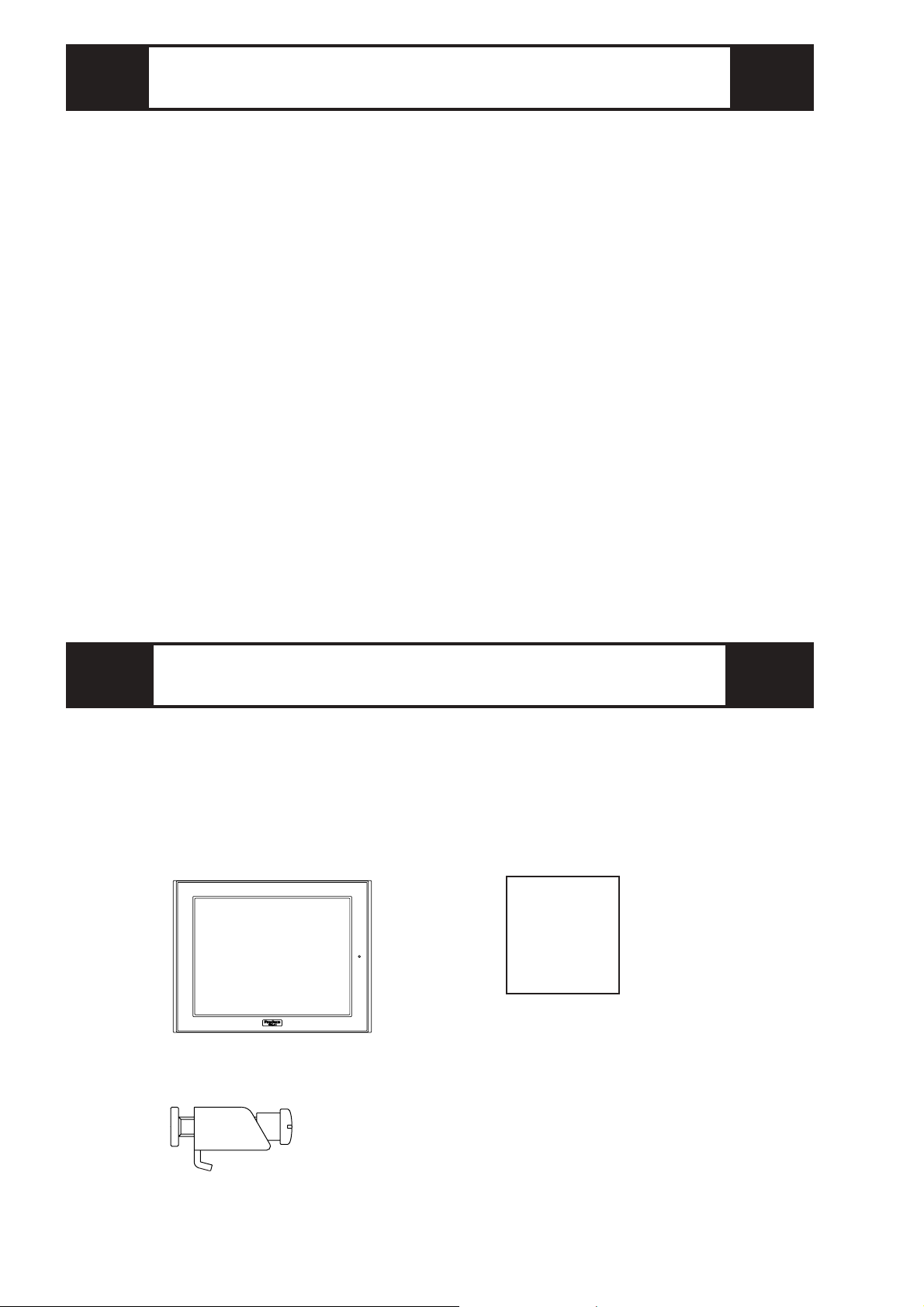
GLC Unit (1)
(GLC2500-TC41-200V/
GLC2600-TC41-200V)
Installation Guide (1)
<This Guide>
Installation Fasteners (4)
Package Contents
Installation
Guide
The GLC2500-TC41-200V and GLC2600-TC41-200V are CE marked prod-
ucts that conform to EMC directives and the Low-voltage directive EN55011
Class A, EN61000-3-2, EN61000-3-3, EN61000-6-2 and EN60950.
For detailed CE marking information, please contact your local GLC distribu-
tor.
<Cautions>
• The GLC unit’s rear face is not approved as an enclosure. When building the
GLC unit into an end-use product, be sure to use an enclosure that satisfies
standards as the end-use product’s overall enclosure.
• The GLC unit must be used indoors only.
• Install and operate the GLC with its front panel facing outwards.
• If the GLC is mounted so as to cool itself naturally, be sure to install it in a
vertical panel. Also, insure that the GLC is mounted at least 100 mm away
from any other adjacent structures or machine parts. If these conditions are
not met, the heat generated by the GLC unit’s internal components may cause
it to fail to meet the standard requirements.
CE Marking

-21-
A : Display
B : Touch Panel
C : Status LED
1Part Names
Color Indicator Operation
Mode*1 Controller
Operation Mode *2
Green ON OFFLINE --- *3
ON Inoperation RUN
Flashing Inoperation STOP
Red ON Inoperation MajorError
Color Indicator
Orange ON Meaning
Backlightburnouthasoccurred.
*1 Operation mode includes Display, SIO Com-
munication and touch key features.
*2 Includes the performance of ladder circuit
program features.
*3 Changing to OFFLINE will release and stop
ladder circuit program features.
Front
Rear
Bottom
CA,B
D I
EF
G
H
JKL
MNOP
D : Power Input Terminal Block
E : Expansion Unit Interface 1
F : Expansion Unit Interface 2
G : CF Card Expansion Interface
H : CF Card Cover
I : CF Card Access LED
J : CF Card Slot (inside cover)
K : Serial Interface (Dsub 25-pin)
L : Expansion Serial Interface
(Dsub 9-pin)
M : Printer Interface
(Half Pitch 20-pin)
N : Ethernet Interface
O : Flex Network LED
P : Screw Lock Terminal Block
Q : Tool Connector Q
-22-
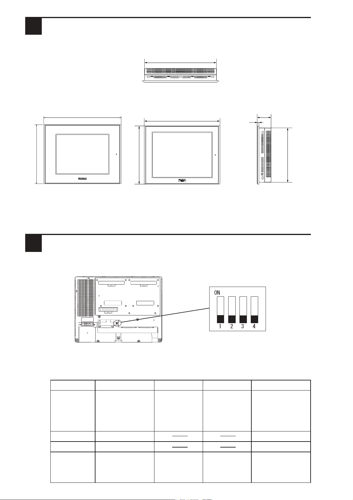
These switches are located inside the CF Card's cover.
Dip Switch Function ON OFF Note
1
This Dip switch
setting controls the
startup from a CF
Card.
Startup from CF
Card is enabled. Startup from CF
Card is
disabled.
CF Card with startu
p
data required.
2Reserved Always OFF
3Reserved Always OFF
4This setting controls
the forced closing of
the CF Card cover.
Forced close
enabled. Forced close
disabled. Used when CF Car
d
cover is damaged.
3CF Card Dip Switches
Dip Switches
(factory set)
Rear of GLC
Unit:mm [in.]
Top
(GLC2500-TC41-200V/GLC2600-TC41-200V)
Side
(GLC2500-TC41-200V/
GLC2600-TC41-200V)
Front
(GLC2600-TC41-200V)
58 [2.28]
8 [0.31]
227 [8.94]
243 [9.57]
301 [11.85]
317 [12.48]
2Dimensions
Front
(GLC2500-TC41-200V)
243 [9.57]
317 [12.48]
-23-
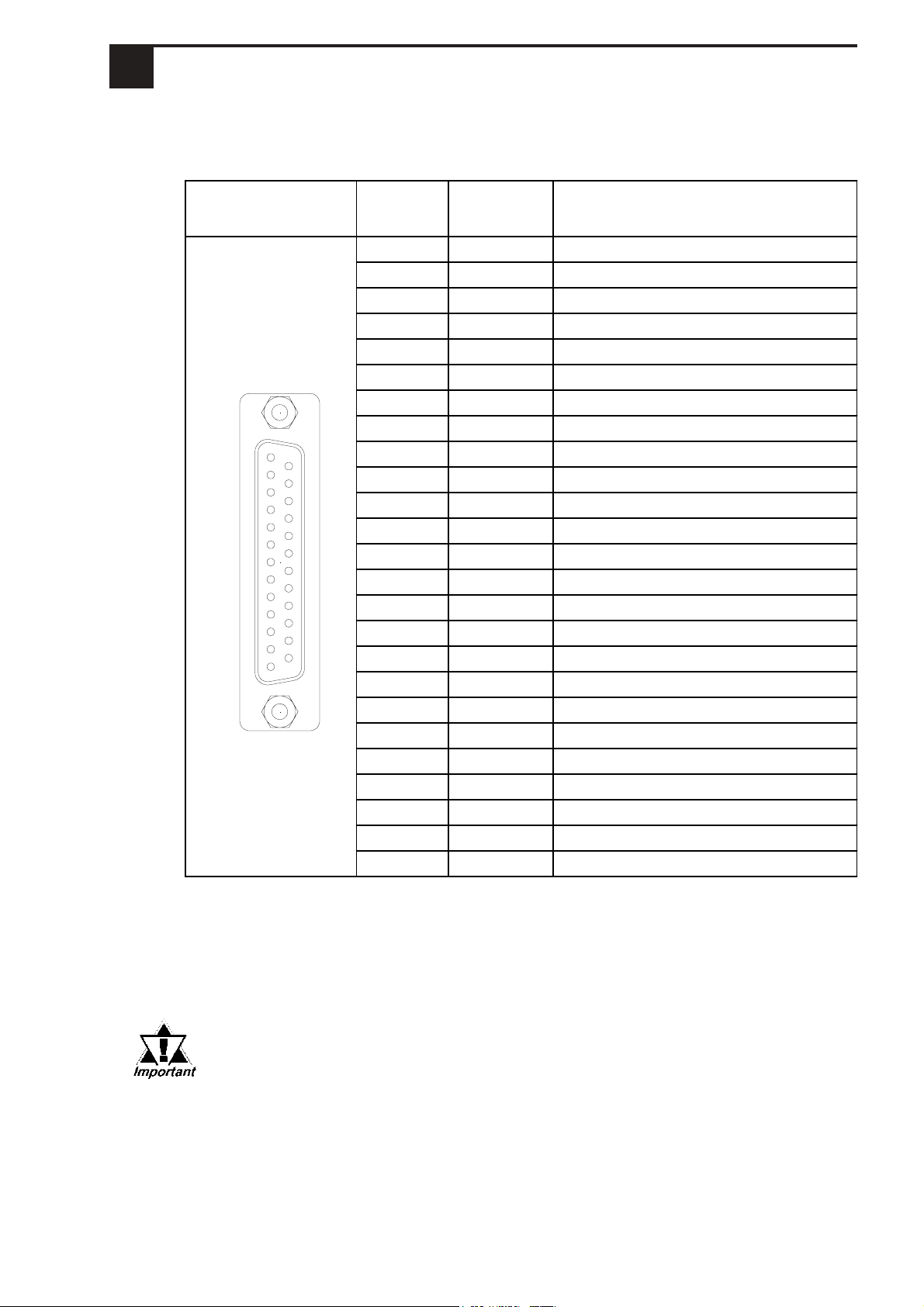
Pin Arrangement Pin # Signal
Name Condition
1 FG Frame Ground
2 SD SendData (RS-232C)
3 RD ReceiveData (RS-232C)
4 RS Requestto Send (RS-232C)
5 CS Clearto Send (RS-232C)
6 DR Data SetReady(RS-232C)
7 SG SignalGround
8 CD CarrierDetect(RS-232C)
9 TRMX Termination(RS-422)
10 RDA Receive Data A (RS-422)
11 SDA SendDataA(RS-422)
12 NC NotConnected (Reserved)
13 NC NotConnected (Reserved)
14 VCC 5V±5%Output0.25A
15 SDB SendDataB(RS-422)
16 RDB Receive Data B (RS-422)
17 RI Ring Indicate (RS-232C)
18 CSB Clearto Send B(RS-422)
19 ERB EnableReceiveB(RS-422)
20 ER EnableReceive(RS-232C)
21 CSA Clearto Send A(RS-422)
22 ERA EnableReceiveA(RS-422)
23 NC NotConnected (Reserved)
24 NC NotConnected (Reserved)
25 NC NotConnected (Reserved)
Serial Interface
4Interfaces
Recommended Connector : Dsub 25-pin plug XM2A-2501 <made by OMRON Corp.>
Recommended Cover : Dsub 25-pin Cover XM2S-2511 <made by OMRON Corp.>
Recommended Screw : Jack Screw XM2Z-0071 <made by OMRON Corp.>
Recommended Cable : CO-MA-VV-SB5P x 28AWG <made by HITACHI Cable Ltd.>
• This GLC unit's serial port is not isolated. When the host (PLC) unit is
also not isolated, and to reduce the risk of damaging the RS-422 circuit,
be sure to connect the #7 SG (Signal Ground) terminal.
• Pin #14 (VCC) DC 5V Output is not protected. To prevent damage or unit
malfunction, use only the designated level of current.
• Inside the GLC unit, the SG (Signal Ground) and FG (Frame Ground)
terminals are connected to each other.
• When connecting an external device to the GLC with the SG terminal,
ensure that no short-circuit loop is created when you setup the system.
114
13 25
This interface is used to connect the GLC to the host (PLC), via an RS-232C
or RS-422 cable.The connector used is a socket-type connector.
-24-
• Use rough metric type M2.6 x 0.45p threads to hold the cable's set (fastening)
screws in place
• For RS-422 Connectors
• The following pairs of pin numbers must be connected (shorted).
...#18 (CSB) <-> #19 (ERB)
...#21 (CSA) <-> #22 (ERA)
• Connecting the #9 (TRMX) and #10 (RDA) wires, adds a termination
resistance of 100ΩΩ
ΩΩ
Ω between RDA and RDB.
• Use a 4-wire cable when the PLC type is Memory Link and the cable is
RS-422.
• For RS-232C Connectors
• Do not connect #9 (TRMX), #10 (RDA), #11 (SDA), #15 (SDB), #16 (RDB),
#18 (CSB), #19 (ERB), #21 (CSA), and #22 (ERA).
• The #1 (FG) terminal should only be connected if it is required by the device
being connected to.
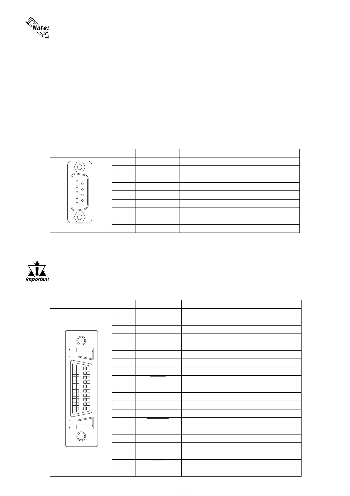
Expansion Serial Interface
The connector used is a plug-type connector.
Printer Interface
Pin Arrangement
Pin #
Signal Name
Meaning
1
CD
Carrier Detect(RS-232C)
2
RD
Receive Data(RS-232C)
3
SD
Send Data(RS-232C)
4
ER
Enable Receive(RS-232C)
5
SG
Signal Ground
6
DR
Data SetReady(RS-232C)
7
RS
Requestto Send(RS-232C)
8
CS
Clear to Send(RS-232C)
9
RI/VCC
Ring Indicate(RS-232C) 5V±5%0.25A
Recommended Connector :Dsub 9-pin socket XM2D-0901 <made by OMRON Corp.>
Recommended Cover :Dsub 9-pin cover XM2S-0913 <made by OMRON Corp.>
Recommended Screw :Jack Screw XM2Z-0073 <made by OMRON Corp.>
Use inch type screws (#4-40UNC) as set screws.
59
16
Pin Arrangement
Pin #
Signal Name
Meaning
1
GND
Ground
2
RESERVE
Reserved
3
PDB5
Data Signal
4
PDB4
Data Signal
5
PDB3
Data Signal
6
GND
Ground
7
SLCT
SelectCondition(Input)
8
PDB0
Data Signal
9
PSTB
Strobe Signal(Output)
10
BUSY
Busy Signal(Input)
11
PDB7
Data Signal
12
PDB6
Data Signal
13
GND
Ground
14
ERROR
Printer Error(Input)
15
GND
Ground
16
PDB2
Data Signal
17
PDB1
Data Signal
18
PE
Paper End
19
INIT
Initialize Signal(Output)
20
GND
Ground
111
10 20
Since Pin#9(RI/VCC) is unprotected, be sure to keep the output cur-
rent within the rated range.
When connecting a printer, use Digital's printer cable (PSM-PRCB00).
-25-
Ethernet Interface
This interface complies with the IEEE802.3 standard for Ethernet (10BASE-
T) connections. This interface uses an RJ-45 type modular jack (8 points).
CF Card Interface
This slot accepts a CF Card.
Expansion CF Card Interface
This interface is for connecting the Front Maintenance CF Card Unit.
Expansion Unit Interface 1
This interface is used to connect an expansion unit that can transmit data over
Expansion Unit Interface 2
Provides expanded features.
Tool Connector
Connects a Data Transfer Cable or bar code reader.
• Before installing the GLC into a cabinet or panel, check that
the installation gasket is securely attached to the unit.
• A gasket which has been used for a long period of time may
have scratches or dirt on it, and could have lost much of its
dust and drip resistance. Be sure to change the gasket peri-
odically (or when scratches or dirt become visible).
Confirm the Installation Gasket's Positioning
It is strongly recommended that you use the gasket. It absorbs vibration in
addition to repelling moisture.
Place the GLC on a level surface with the display panel facing downward.
Check that the GLC’s installation gasket is seated securely into the gasket’s
groove, which runs around the perimeter of the panel’s frame.
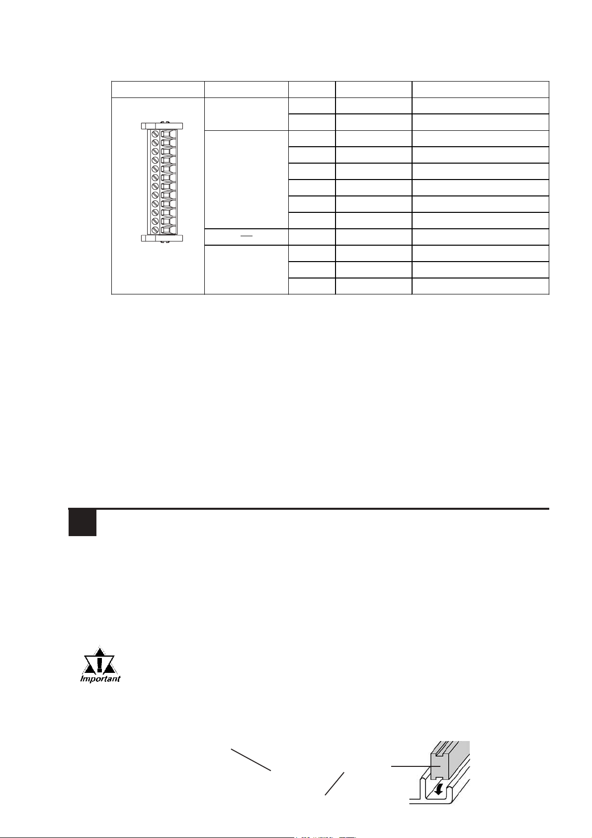
Screw Lock Terminal Block
This interface is used for external reset, Flex Network conections, or sound
output.
Pin Arrangement
I/F
Pin No.
Signal Name
Meaning
External Reset 1 AUXCOM External Reset Common
2 AUXRESET External Reset Input
Flex Network I/F 3 TR+ CH1 Comunication Data
4 TR- CH1 Comunication Data
5 SLD CH1 Cable, Sheild
6 TR+ CH2 Comunication Data
7 TR- CH2 Comunication Data
8 SLD CH2 Cable, Sheild
9 Reserved Reserved
Sound I/F 10 SPOUT Speaker OutputTerminal
11 GND Ground
12 LINEOUT Line OutOutputTerminal
1
12
5Installation
Gasket
Rear face
-26-
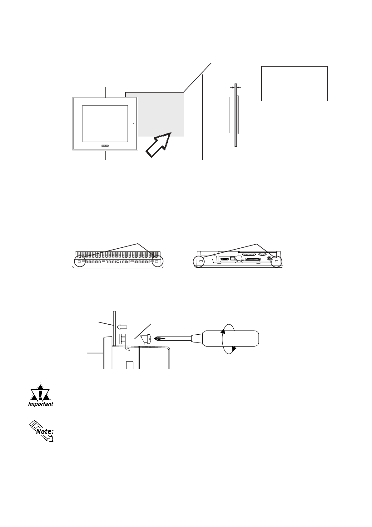
Attach the Installation Fasteners from Inside the Panel
The following figures show the four (4) fastener insertion slot locations. In-
sert each fastener's hook into the slot and tighten it with a screwdriver.
Create a Panel Cut and insert the GLC into the panel from the
front
Installation
fastener
Panel
GLC
Insertion Slots Insertion Slots
Top Bottom
Unit: mm [in]
+1
0 +0.04
0
under 4-R3
Panel Panel thickness:
1.6mm[0.06in] to
10mm[0.39in]
301.5 [11.87 ]
GLC
GLC
Panel
+1
0
227.5
[8.96 ]
+0.04
0
• Tightening the screws with too much force can damage the
GLC's plastic case.
• The necessary torque is 0.5 N•m.
• Depending on the installation panel's thickness, etc., the number of
installation fasteners used may need to be increased to provide the
desired level of moisture resistance.

-27-
• To avoid a short caused by loose ring terminals, be sure to use ring termi-
nals with an insulating sleeve. *1
• When the FG terminal is connected, be sure the wire is grounded. Not
grounding the GLC unit will result in excess noise and vibration.
• Wherever possible, use thick wires (max. 2 mm2) for power terminals, and
twist the wire ends before attaching the ring terminals.
• Be sure to use the following size ring terminals.
Connecting the GLC Power Cord
When connecting the power cord, be sure to follow the procedures given
below.
1. Confirm that the GLC's Power Cord is unplugged from the power supply.
2. Use a screwdriver to remove the Power Input Terminal Block's clear plastic
cover.
3. Unscrew the screws from the middle three (3) terminals, align the Ring
Terminals and re-attach the screws.
4. Replace the Power Input Terminal Block's clear plastic cover.
• Confirm that the ring wires are connected correctly.
• The torque required to tighten these screws is 0.5 to 0.6 N•m.
•To avoid an electric shock, when connecting the GLC's power
cordterminals to the powerterminalblock, confirm that theGLC's
power supply is completely turned OFF, via a breaker, or similar
unit.
•The GLC2500-TC41-200V and GLC2600-TC41-200V units are
designed to use only with 100 V to 240V AC input. Any other
power level can damage both the GLC and the power supply.
•Since there is no power switch on the GLC unit, be sure to
attach a breaker-type switch to its power cord.
• When the FG terminal is connected, be sure the wire is
grounded.
6Wiring
WARNINGS
Power Input
Terminal Block
Ring Terminals*1
*1 L=AC Input Live Line
N=AC Input Neutral Line
FG=Grounding Terminal connected to the GLC chassis.
Suggested Ring Terminal : equivalent to V2-MS3 (made by JST)
Rear of GLC

-28-
• When attaching a wire to the GLC's rear face FG terminal, (on the Power Input
Terminal Block), be sure to create an exclusive ground.
• Inside the GLC2500-TC41-200V/GLC2600-TC41-200V units, the SG (Signal
Ground) and FG(Frame Ground) terminals are connected to each other.
• When connecting an external device to the GLC with the SG terminal, ensure
that no short-circuit loop is created when you setup the system.
• When attaching an expansion unit to the GLC, be sure to read the expansion
unit's Installation Guide.
Please pay special attention to the following instructions when connecting the
power cord terminals to the GLC unit.
•If the power supply voltage exceeds the GLC's specified range, connect a
voltage transformer.
•Between the line and the ground, be sure to use a low noise power supply. If
there is still an excessive amount of noise, connect a noise reducing trans-
former.
•Input and Output signal lines must be separated from the power control cables
for operational circuits.
•To increase the noise resistance, be sure to twist the ends of the power cord
wires before connecting it to the GLC unit.
•The GLC's power supply cord should not be bundled with or kept close to
main circuit lines (high voltage, high current), or input/output signal lines.
•Connect a surge absorber to handle power surges.
•To reduce noise, make the power cord as short as possible.
•All GLC Input and Output signal lines must be separated from all operating
circuit (power) cables.
•If this is not possible, use a shielded cable and ground the shield.
9Input/Output Signal Line Cautions
8Grounding Cautions
7Power Supply Cautions
The GLC unit's backlight is user replacable.
Do not use of a different model backlight, since it may cause
a GLC malfunction or breakdown.
For an explanation of how to replace the GLC's backlight, please refer to the
User Manual or the Installation Guide which comes with the replacement back-
lights (sold separately).
10 Replacing the Backlight
*1 For GLC2600 Series, the backlight differs depending on a Rev.
For the correct backlight and how to distinguish Rev., refer to
the User Manual carried in the Pro-face Web Site
(http://www.pro-face.com/).
GLC Unit Rev. Required Backlight Model
GLC2500-TC41-200V - GP577RT-BL00-MS
Rev.4 is marked CA3-BLU12-01
The others PS600-BU00
GLC2600-TC41-200V*1
This manual suits for next models
1
Table of contents
Other Pro-face Control Panel manuals

Pro-face
Pro-face GC4000 Series User manual

Pro-face
Pro-face Pro-face ST Series User manual

Pro-face
Pro-face GP-3500 Series User manual

Pro-face
Pro-face GLC2500-TC41-24V User manual

Pro-face
Pro-face GP-2300 Series User manual

Pro-face
Pro-face GP-4100 series User manual

Pro-face
Pro-face GP3000U Series User manual

Pro-face
Pro-face AGP3300-U1-D24 User manual
Popular Control Panel manuals by other brands


Bentel Security
Bentel Security FireClass 100 user guide

Rosslare
Rosslare AC-225-B Series Hardware installation

Salda
Salda Ptouch Service manual

Endress+Hauser
Endress+Hauser Liquiline CM442 Brief operating instructions

ESP
ESP MAGDUO8B user manual

Secutron
Secutron MR-2300T Installation and operation manual


