PRO Light EclDisplay UNFC User manual

USER MANUAL
REV.01-02/21 English version
EclDisplay DATFC
EclDisplay UNFC
40W RGB+WW LED gallery light

Thank you for choosing PROLIGHTS
Please note that every PROLIGHTS product has been designed in Italy to meet quality and performance requirements
for professionals and designed and manufactured for the use and application as shown in this document.
Any other use, if not expressly indicated, could compromise the good condition/operation of the product and/or be
a source of danger.
This product is meant for professional use. Therefore, commercial use of this equipment is subject to the respectively
applicable national accident prevention rules and regulations.
Features, specications and appearance are subject to change without notice. Music & Lights S.r.l. and all afliated
companies disclaim liability for any injury, damage, direct or indirect loss, consequential or economic loss or any other
loss occasioned by the use of, inability to use or reliance on the information contained in this document.
Product user manual can be downloaded from the website www.prolights.it , or can be inquired to the ofcial
PROLIGHTS distributors of your territory (https://www.prolights.it/sales_network.html).
Scanning the below QR Code, you will access the download area of the product page, where you can nd a broad
set of always updated technical documentation: specications, user manual, technical drawings, photometrics,
personalities, xture rmware updates.
The PROLIGHTS Logo, PROLIGHTS names and all other trademark in this document pertaining to PROLIGHTS services
or PROLIGHTS product are trademarks OWNED or licensed by Music & Lights S.r.l., its afliates, and subsidiaries.
PROLIGHTS is a registered trademark by Music & Lights S.r.l. All right reserved. Music & Lights – Via A. Olivetti, snc -
04026 - Minturno (LT) ITALY
Visit the download area
of the product page
ECLDISPLAYUNFC ECLDISPLAYDATFC

PROLIGHTS - EclDisplay UNFC / EclDisplay DATFC 01
INDEX
SAFETY INFORMATION 02
1 - PACKAGING 05
PACKAGE CONTENT..................................................................................................... 05
2 - OPTIONAL ACCESSORIES 05
DEDICATED ACCESSORIES........................................................................................... 05
NORDIC ALUMINUM TRACK........................................................................................ 05
3 - TECHNICAL DRAWING 06
4 - TILT RANGE 08
5 - INSTALLATION 09
MOUNTING.................................................................................................................... 09
6 - CONNECTION TO THE MAINS SUPPLY 10
7 - START UP 13
CONNECT AND DISCONNECT POWER FROM THE PRODUCT.................................. 13
8 - PRODUCT OVERVIEW 13
9 - CONTROL PRIORITY ORDER 14
10 - RDM FUNCTIONS 15
11 - ERROR MESSAGES 19
12 - DMX CHARTS 20
13 - ACCESSORIES INSTALLATION 23
OPTIC (CODES ECLDISPWASHL1530 / ECLDISPWASHL2550 / ECLDISPPRZL2040 -
OPTIONAL)..................................................................................................................... 23
BARNDOOR AND FILTER FRAME (CODE ECLDISPBDNFFB - OPTIONAL) .................. 25
ANTI-GLARE LOUVRE (CODE ECLDISPLOUVRE - OPTIONAL)..................................... 26
GOBO HOLDER (CODE ECLDISPGOBOHIND - OPTIONAL)........................................ 27
HALF SNOOT, FULL SNOOT (CODES ECLDISPHSNOOT, ECLDISPFSNOOT -
OPTIONAL)..................................................................................................................... 28
CEILING ADAPTER KIT (CODES ECLDISPCEILKIT, ECLDISPCEILFLG - OPTIONAL) .... 29
14 - MAINTENANCE 32
MAINTENANCE AND CLEANING THE PRODUCT........................................................ 32
VISUAL CHECK OF PRODUCT HOUSING ..................................................................... 32
TROUBLESHOOTING..................................................................................................... 33
PROLIGHTS - EclDisplay UNFC / EclDisplay DATFC02
SAFETY INFORMATION
WARNING!
• Please read carefully the instruction reported in this section before installing, power-
ing, operating or servicing the product and observe the indications also for its future
handling.
This unit is not for household use, only professional applications.
Connection to mains supply
• The Connection to the mains supply must be carried out by a qualied electrical
installer.
• Use only AC supplies 100-240V 50-60 Hz, the xture must be electrically connected
to ground (earth).
• Select the cable cross section in according with the maximum current draw of the
product and the possible number of products connected at the same power line.
• The AC mains power distribution circuit must be equipped with magnetic+residual
current circuit breaker protection.
• Do not connect it to a dimmer system; doing so may damage the product.
Protection and Warning against electrical shock
• Do not remove any cover from the product, always disconnect the product from AC
power before servicing.
• Ensure that the xture is electrically connected to ground (earth). And use only a
source of AC power that complies with local building and electrical codes and has
both overload and ground-fault (earth-fault) protection.
• Before using the xture, check that all power distribution equipment and cables are
in perfect condition and rated for the current requirements of all connected devices.
• Isolate the xture from power immediately if the power plug or any seal, cover, ca-
ble, or other components are damaged, defective, deformed or showing signs of
overheating.
• Do not reapply power until repairs have been completed.
• Refer any service operation not described in this manual to PROLIGHTS Service team
or an authorized PROLIGHTS service center.
Installation
• Make sure that all visible parts of the product are in good visible condition before its
use or installation.
• Make sure the point of anchorage is stable before positioning the projector.
• When suspending the xture above ground level, secure it against failure of primary
attachments by attaching a safety cable that is approved as a safety attachment for
the weight of the xture to the attachment point on the main frame of the product. ln
case the safety cable, enter in action, it needs to be replaced with a new one.
• Install the product only in well ventilated places.
• For non temporary installations, ensure that the xture is securely fastened to a load-
bearing surface with suitable corrosionresistant hardware.
• For a temporary installation with clamps, ensure that the quarter-turn fastener and/or
screws are turned fully, and secured with a suitable safety cable.
0,2 m Minimum distance of illuminated objects
• The projector needs to be positioned so that the objects hit by the beam of light are
at least 0.2 meters (0.65 ft) from the lens of the projector.

PROLIGHTS - EclDisplay UNFC / EclDisplay DATFC 03
T 45°C
a
Max operating ambient temperature (Ta)
• Do not operate the xture if the ambient temperature (Ta) exceeds 45 °C (113 °F).
T
-10°
C
a
Minimum operating ambient temperature (Ta)
• Do not operate the xture if the ambient temperature (Ta) is below -10 °C (14 °F).
Protection from burns and re
• The exterior of the xture becomes hot during use. Avoid contact by persons and
materials.
• Ensure that there is free and unobstructed airow around the xture.
• Keep ammable materials well away from the xture
• Do not expose the front glass to sunlight or any other strong light source from any an-
gle. Lenses can focus the sun’s rays inside the xture, creating a potential re hazard.
• Do not attempt to bypass thermostatic switches or fuses.
Indoor use
• This product is designed for indoor and dry environments.
• Do not use in wet location and do not expose the xture to rain or moisture.
• Never use the xture in places subject to vibrations or bumps.
• Make certain that no inammable liquids, water or metal objects enter the xture.
• Excessive dust, smoke uid, and particle build up degrades performance, causes
overheating and will damage the xture.
• Damages caused by inadequate cleaning or maintenance are not covered by the
product warranty.
T
65°
C
c
Temperature of the external surface
• The surface of the xture can reach up to 65 °C (149 °F) during operation. Avoid
contact with people and materials.
Photobiological safety
• This device emits potentially dangerous optical radiation and is identied in the cat-
egory of Risk Group 1 according to EN 62471.
Maintenance
• Warning! Disconnect the xture from AC mains power and allow to cool for at least
10 minutes before handling.
• Only technicians who are authorized by PROLIGHTS or Authorised service partners
are permitted to open the xture.
• Users may carry out external cleaning, following the warnings and instructions pro-
vided, but any service operation not described in this manual must be referred to a
qualied service technician.
• Important! Excessive dust, smoke uid, and particle build up degrades performance,
causes overheating and will damage the xture. Damages caused by inadequate
cleaning or maintenance is not covered by the product warranty.
Do not stare at the operating light source
• Do not look directly at the LED source during operation. It can be harmful to the eyes
and skin.
• During Installation, operation and maintenance, be prepared for the xture to light
and move suddenly when connected to power.

PROLIGHTS - EclDisplay UNFC / EclDisplay DATFC04
Disposal
• This product is supplied in compliance with European Directive 2012/19/EU – Waste
Electrical and Electronic Equipment
• (WEEE). To preserve the environment please dispose/ recycle this product at the end
of its life according to the local regulation.
The products to which this manual refers comply with:
• 2014/35/EU - Safety of electrical equipment supplied at low voltage (LVD);
• 2014/30/EU - Electromagnetic Compatibility (EMC);
• 2011/65/EU - Restriction of the use of certain hazardous substances (RoHS).

PROLIGHTS - EclDisplay UNFC / EclDisplay DATFC 05
1 - PACKAGING
PACKAGE CONTENT
• 1x ECLDISPLAYUNFC or 1x ECLDISPLAYDATFC;
• User Manual.
2 - OPTIONAL ACCESSORIES
DEDICATED ACCESSORIES
• ECLDISPWASHL1530B/W: zoomable Wash Lens 15-30° for EclDisplay, black/white housing;
• ECLDISPWASHL2550B/W: zoomable Wash Lens 25-50° for EclDisplay, black/white housing;
• ECLDISPPRZL2040B/W: zoomable Prole Lens 20-40°, with 4 framing shutters, for EclDisplay, black/white housing;
• ECLDISPCEILKIT: ceiling adapter kit for EclDisplay, black/white ange;
• ECLDISPHSNOOTB/W: half snoot for EclDisplay, black/white housing;
• ECLDISPFSNOOTB/W: full snoot for EclDisplay, black/white housing;
• ECLDISPLOUVREB/W: anti-glare louvre for EclDisplay, black/white housing;
• ECLDISPBDNFFB/W: barndoor and lter frame (compatible with Wash Lenses) for EclDisplay, black/white housing;
• ECLDISPGOBOHINDB/W: gobo holder for EclDisplay with manual adjustable index position system, black/white housing;
• ECLDISPCEILFLGB/W: ange to complete the EclDisplay ceiling adapter kit, black/white;
• PLCPW93075: power PVC cable H05VV-F 3G0,75;
• PLCDX53D5: 120ohm DMX cable, 2 twisted poles, external sheath with reduced diameter;
• PLCPD7501P14D: power & DMX 120 Ohm;
• C6002: slim aluminium clamp, 200 kg loading, 48-51 mm tubes, M10 bolt;
• RSR0630A/B: steel security cable for hanging bodies, inox steel shackle, L=60 cm, silver/black;
• UPBOX1U: rmware uploader kit, USB IN, 3p XLR DMX OUT.
NORDIC ALUMINUM TRACK
NOTE: the nal terms "2" and "3" in the codes indicate the corresponding color variant in black and white respectively.
• NAXTSA682/3: global Pulse 3-Circuit MULTI Adapter, 10A 100N Slot connection, black/white;
• NAGAC6002/3: global Pulse DALI 3-Circuit Adapters, 10A 100N Slot connection, black/white;
• NAXTSA57129: global Pulse Rotating Nipples 3-Circuit Adapters, M10, H 12MM;
• NAXTSA55129: global Pulse Rotating Nipples 3-Circuit Adapters, M13, H 12mm, D 9mm;
• NAGAM109: global Pulse Nut M10 for NAXTSA57129;
• NAGAM139: global Pulse Nut M13 for NAXTSA55129;
• NAXTSC61002/3: global Pulse XTSC Lighting Track, 3 circuit DALI, 1000mm, black/white;
• NAXTSC62002/3: global Pulse XTSC Lighting Track, 3 circuit DALI, 2000mm, black/white;
• NAXTSC63002/3: global Pulse XTSC Lighting Track, 3 circuit DALI, 3000mm, black/white;
• NAXTSC64002/3: global Pulse XTSC Lighting Track, 3 circuit DALI, 4000mm, black/white;
• NAXTSC6112/3: global Pulse XTS Connector 3-CCT DALI end feed, earth right, black/white;
• NAXTSC6122/3: global Pulse XTS Connector 3-CCT DALI end feed, earth left, black/white;
• NAXTSC6142/3: global Pulse XTS Connector 3-CCT DALI middle feed, black/white;
• NAXTSC6232/3: global Pulse XTS Connector 3-CCT DALI exible corner connector, black/white;
• NAXTSNC6342/3: global Pulse XTSN Connector 3-CCT DALI L connector, earth right, black/white;
• NAXTSNC6352/3: global Pulse XTSN Connector 3-CCT DALI L connector, earth left, black/white;
• NAXTSNC6362/3: global Pulse XTSN Connector 3-CCT DALI T connector, earth right/right, black/white;
• NAXTSNC6372/3: global Pulse XTSN Connector 3-CCT DALI T connector, earth left/left, black/white;
• NAXTSNC6382/3: global Pulse XTSN Connector 3-CCT DALI X connector, black/white;
• NAXTSNC6392/3: global Pulse XTSN Connector 3-CCT DALI T connector, earth right/left, black/white;
• NAXTSNC6402/3: global Pulse XTSN Connector 3-CCT DALI T connector, earth left/right, black/white;
• NAXTS412/3: global Pulse XTS Connector 3-CCT DALI END cap, black/white;
• NASPW12SK215M: global Pulse Track clip wire suspension set 1.5m, 150N, black;
• NASPW12SK25M: global Pulse Track clip wire suspension set 5m, 150N, black;
• NASPW12SK315M: global Pulse Track clip wire suspension set 1.5m, 150N, white;
• NASPW12SK35M: global Pulse Track clip wire suspension set 5m, 150N, white;
• NASKB122/3: global Pulse Track Mounting Clamp for Rod and Wire, 200N, black/white.
PROLIGHTS - EclDisplay UNFC / EclDisplay DATFC06
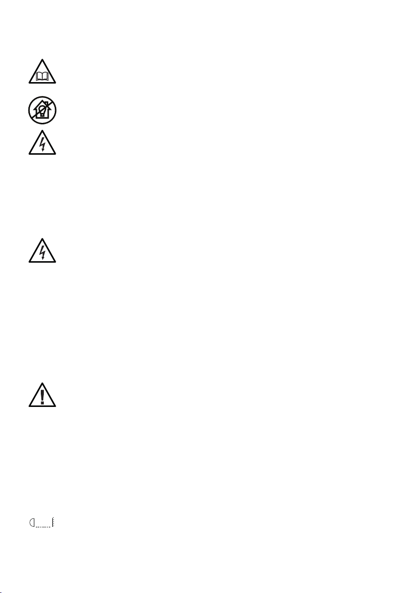
3 - TECHNICAL DRAWING
200 mm [7.9 in]
124 mm [4.9 in]
228 mm [9.0 in]148 mm [5.8 in]
270 mm [10.6 in]
Weight: 2.01 kg - 4.43 lbs ECLDISPLAYUNFC with ECLDISPWASHL1530
145 mm [5.7 in]
200 mm [7.9 in]
219 mm [8.6 in]
124 mm [4.9 in]
260 mm [10.3 in]
Weight: 2.00 kg - 4.41 lbs ECLDISPLAYUNFC with ECLDISPWASHL2550
229 mm [9.0 in]
184 mm [7.2 in] 303 mm [11.9 in]
160 mm [6.3 in]
345 mm [13.6 in]
345 mm [13.6 in]
Weight: 2.18 kg - 4.80 lbs ECLDISPLAYUNFC with ECLDISPPRZL2040
Dimensions are in mm / in - Fig. 01
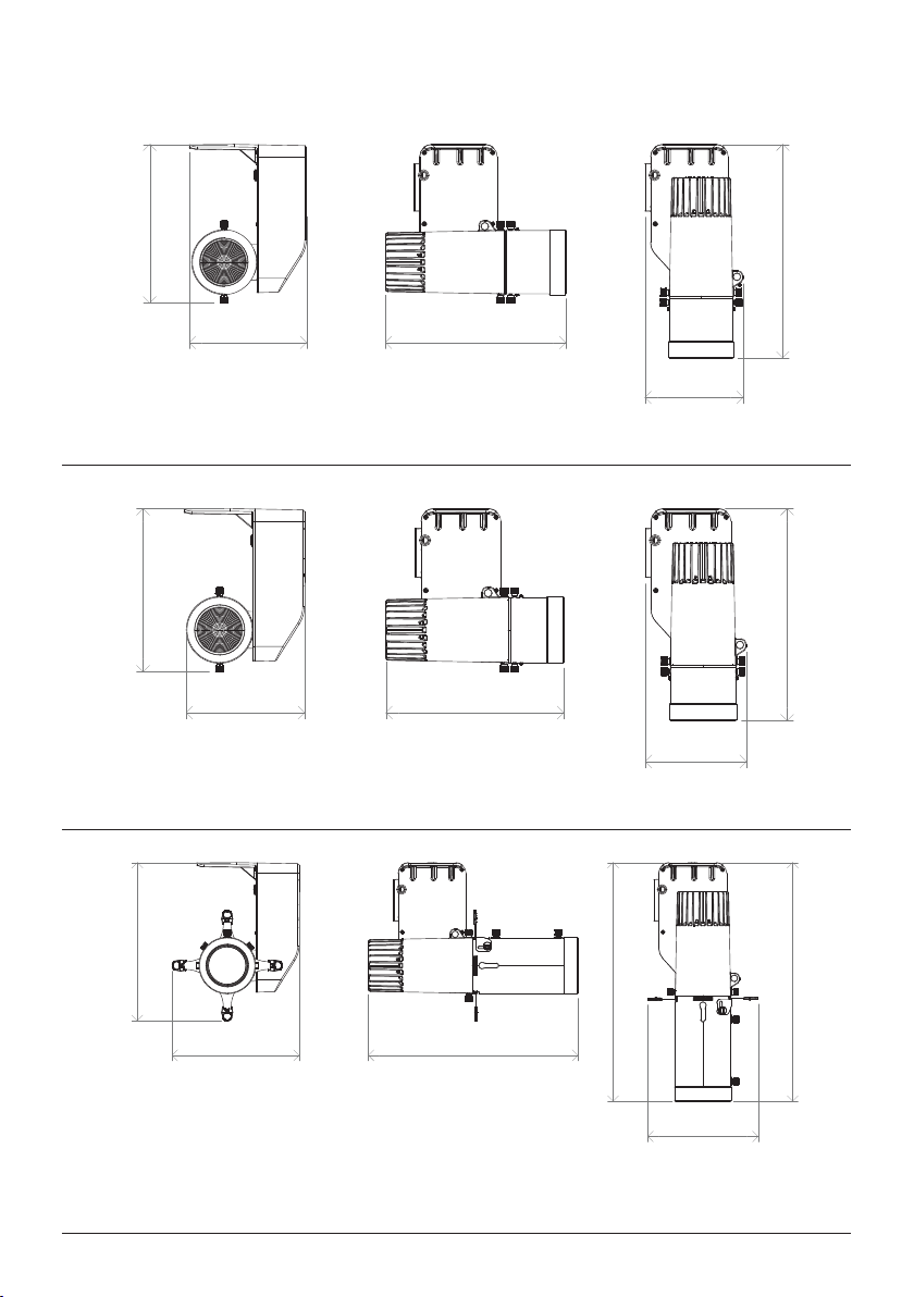
PROLIGHTS - EclDisplay UNFC / EclDisplay DATFC 07
138 mm [5.4 in]
200 mm [7.9 in]
228 mm [9.0 in]
105 mm [4.1 in]
270 mm [10.6 in]
Weight: 1.78 kg - 3.92 lbs ECLDISPLAYDATFC with ECLDISPWASHL1530
138 mm [5.4 in]
200 mm [7.9 in]
218 mm [8.6 in]
105 mm [4.1 in]
260 mm [10.3 in]
Weight: 1.77 kg - 3.90 lbs ECLDISPLAYDATFC with ECLDISPWASHL2550
177 mm [7.0 in]
229 mm [9.0 in]
303 mm [11.9 in]
160 mm [6.3 in]
345 mm [13.6 in]
Weight: 1.95 kg - 4.29 lbs ECLDISPLAYDATFC with ECLDISPPRZL2040
Dimensions are in mm / in - Fig. 02

PROLIGHTS - EclDisplay UNFC / EclDisplay DATFC08
4 - TILT RANGE
135°
Fig. 03
PROLIGHTS - EclDisplay UNFC / EclDisplay DATFC 09
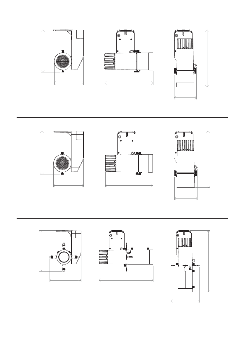
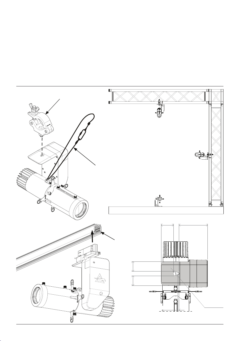
5 - INSTALLATION
MOUNTING
Check that the supporting structure can safely bear the weight of all installed xtures, clamps, cables,
auxiliary equipment, etc. and complies with locally applicable regulations.
When suspending the xture above ground level, secure it against failure of primary attachments by
attaching a safety wire that is approved as a safety attachment for the weight of the xture to an anchor
point on the product main frame.
Do not use removable parts or weak anchors for secondary attachment.
Warning! When clamping the xture to a truss or other structure at any angle, use clamps of half-cou-
pler type. Do not use any type of clamp that does not completely encircle the structure when fastened.
Dimensions are in mm / in - Fig. 04
C6002
clamp
RSR Steel security cable
30 [1.2] 30 [1.2]
4 [0.2]
37 [1.5] 87 [3.4]
Ø14 [Ø0.5]
Track system
PROLIGHTS - EclDisplay UNFC / EclDisplay DATFC10
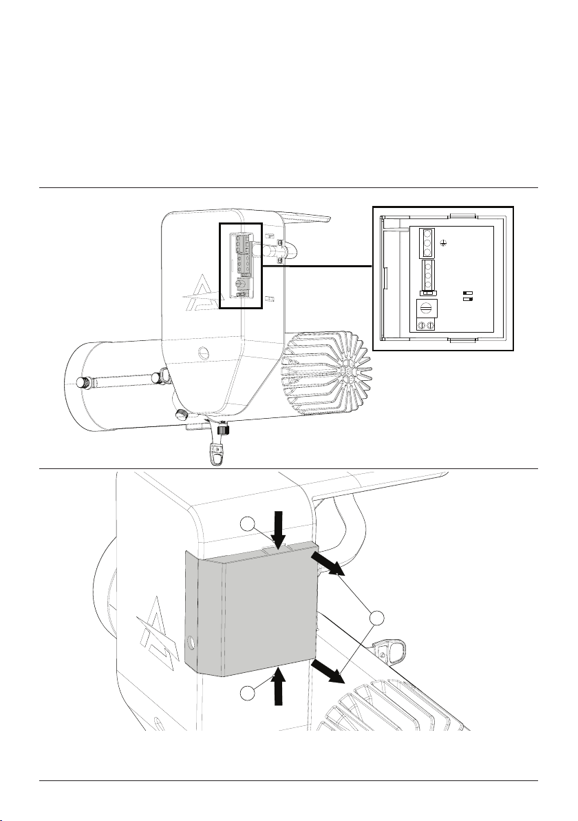
6 - CONNECTION TO THE MAINS SUPPLY
WARNING: For protection from electric shock, the xture must be earthed!
The product is equipped with auto-switching power supply that automatically adjusts to any 50-60Hz
AC power source from 100-240 Volts.
If you need to install a power plug on the power cable to allow connection to power outlets, install a
grounding-type (earthed) plug, following the plug manufacturer’s instructions. If you have any doubts
about proper installation, consult a qualied electrician.
The max power consumption is 48W.
ECLDISPLAYUNFC
DIMMER
POWER / SIGNAL
L
N
GND
DMX- / DALI2
DMX+ / DALI1
SWITCH DALI
DMX
1
1
2
Press the top and bottom sides of the cage at the indicated point (1). Then remove it (2).
Fig. 05

PROLIGHTS - EclDisplay UNFC / EclDisplay DATFC 11
ECLDISPLAYDATFC
DIMMER
POWER
SIGNAL
L
N
GND DMX-
DALI2
DMX+
DALI1
OR
DALI
DMX
1
2
2
1
Press down on the sides of the cage (1). Then remove it (2).

PROLIGHTS - EclDisplay UNFC / EclDisplay DATFC12
2
3
Loosen and remove the marked four screws (2). Then remove the arm housing (3).
Fig. 06
PROLIGHTS - EclDisplay UNFC / EclDisplay DATFC 13
23
4
5
1
7 6
2
3
8
9
76
2
3
8
9
7 - START UP
CONNECT AND DISCONNECT POWER FROM THE PRODUCT
To apply and disconnect power to the product:
• Check that the product is installed and secured as indicated in the Safety Informations, and that
personal safety will not be put at risk when the xture lights up.
• Connect the power connector into the Mains input socket (100-240 VAC-50/60 Hz).
• The product is then ready for its operations and can be controlled through the available input sig-
nals on board.
• To disconnect power from the product, disconnect the Mains from the socket.
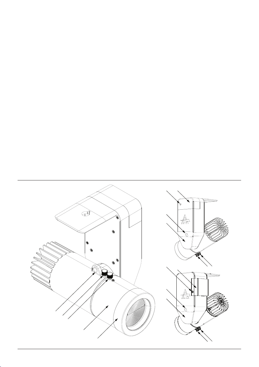
8 - PRODUCT OVERVIEW
1. SAFETY EYE to attach safety cable;
2. KNOB for releasing and locking the optic;
3. KNOB for releasing and locking the optic and for zoom;
4. OPTIC (accessory not included, in the gure ECLDISPWASHL1530);
5. RUBBER RING (accessory included in the box optic);
6. PLASTIC CAP for access to connections;
7. KNOB dimming;
8. LOCK TILT;
9. PLASTIC ARM COVER.
Fig. 07

PROLIGHTS - EclDisplay UNFC / EclDisplay DATFC14
Fig. 08
Phase-Cut Dimming (UN)
Knob Dimming
DMX /
DALI
9 - CONTROL PRIORITY ORDER
The control with higher priority denes the maximum dimming level of the successive inputs.
There is an dip switch to rapidly change between DALI or DMX (though DMX is set as default).

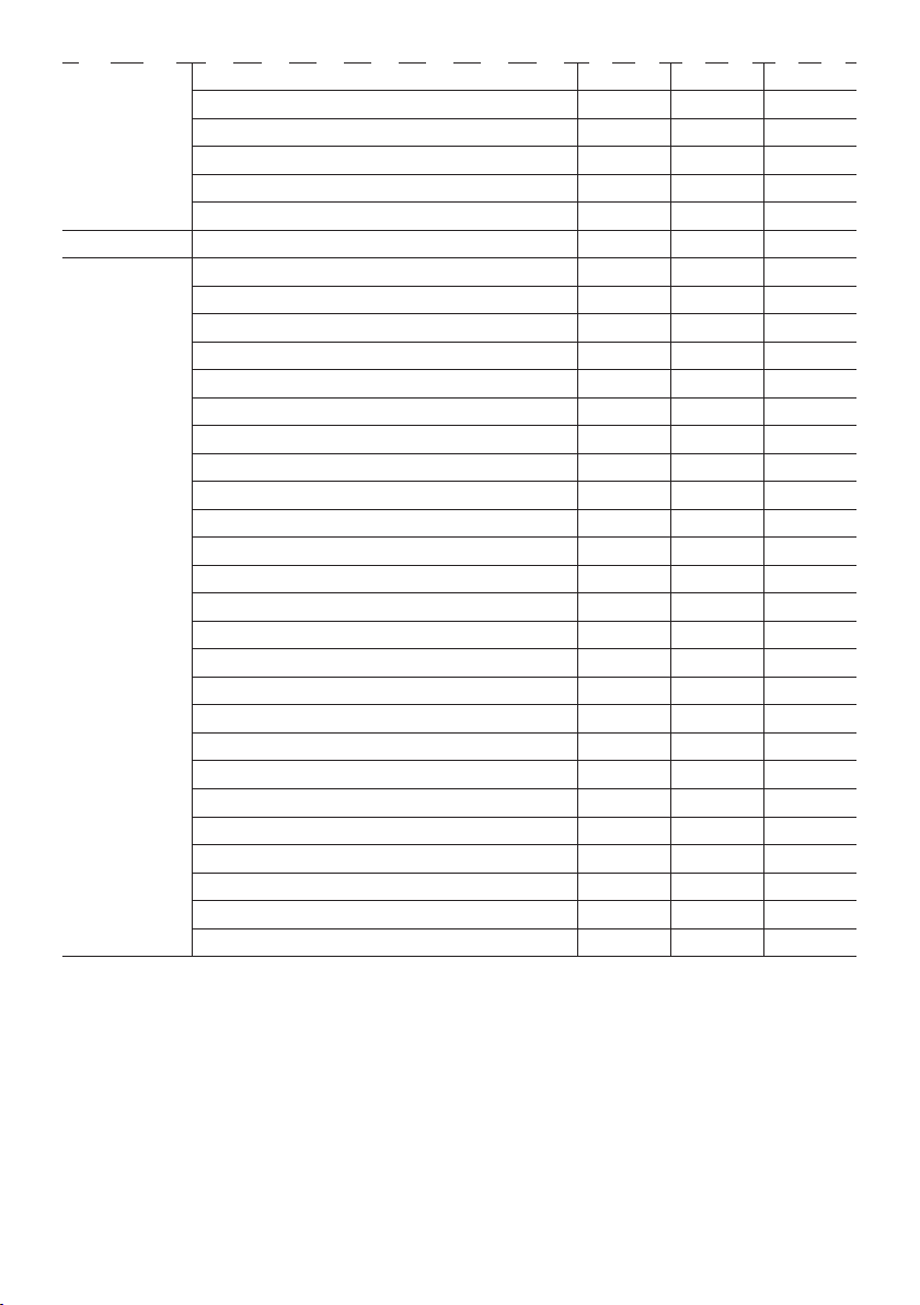
Category Parameter PID GET SET
Product
Information
DEVICE_INFO 0x0060 x
PRODUCT_DETAIL_ID_LIST 0x0070 x
DEVICE_MODEL_DESCRIPTION 0x0080 x
MANUFACTURER_LABEL 0x0081 x
DEVICE_LABEL 0x0082 x x
FACTORY_DEFAULTS 0x0090 x x
SOFTWARE_VERSION_LABEL 0x00C0 x
DMX512
Setup
DMX_PERSONALITY* 0x00E0 x x
DMX_PERSONALITY_DESCRIPTION 0x00E1 x
DMX_START_ADDRESS* 0x00F0 x x
SLOT_INFO 0x0120 x
SLOT_DESCRIPTION 0x0121 x
DEFAULT_SLOT_VALUE 0x0122 x
Dimmer
Settings
DIMMER_INFO 0x0340 x
CURVE* 0x0343 x x
CURVE_DESCRIPTION 0x0344 x x
OUTPUT_RESPONSE_TIME* 0x0345 x x
OUTPUT_RESPONSE_TIME_ DESCRIPTION 0x0346 x
MODULATION_FREQUENCY* 0x0347 x x
MODULATION_FREQUENCY_ DESCRIPTION 0x0348 x
Sensors SENSOR_VALUE 0x0201 x x
Product Model ID Mode IDs
ECLDISPLAYUNFC D062
BASIC: 1
STANDARD: 2
EXTENDED: 3
ECLDISPLAYDATFC D063
BASIC: 1
STANDARD: 2
EXTENDED: 3
PROLIGHTS - EclDisplay UNFC / EclDisplay DATFC 15
10 - RDM FUNCTIONS
The product can communicate using RDM (Remote Device Management) protocol over a DMX512
Networks.
RDM is a bi-directional communications protocol for use in DMX512 control systems, it is the open
standard for DMX512 device conguration and status monitoring.
The RDM protocol allows data packets to be inserted into a DMX512 data stream without affecting
existing non-RDM equipment. It allows a console or dedicated RDM controller to send commands to
and receive messages from specic xtures.
The PIDs in the following tables are supported in the product.
Power/Lamp
Settings
DEVICE_HOURS 0x0400 x x
LAMP_HOURS 0x0401 x x
LAMP_STRIKES 0x0402 x x
LAMP_STATE 0x0403 x x
LAMP_ON_MODE 0x0404 x x
DEVICE_POWER_CYCLES 0x0405 x x
Control IDENTIFY_DEVICE 0x1000 x x
Special PIDs** 0:BLACKOUT,1:HOLD,2:STAND ALONE 0x82DD x x
0:MST DMX 1:MST NO DMX 2:SLAVE 0x8211 x x
0:STATIC 1:CCT 2:MACRO 3:RGBW 0x82EC x x
STATIC COLORS:0~14:R G B W 0x82BE x x
WHITE PRESETS:0~20:2800K 3000K 0x82BF x x
COLOR MACROS 0:R 1:G 2:B 3:.. 0x82ED x x
MANUAL BLUE 0x82C2 x x
MANUAL GREEN 0x82C1 x x
MANUAL RED 0x82C0 x x
MANUAL WARM WHITE 0x82C3 x x
FULL ON 0:HB MODE 1:STUDIO MODE 0x8217 x x
STUDIO BLUE 0x82CB x x
STUDIO GREEN 0x82CA x x
STUDIO RED 0x82C9 x x
STUDIO WARM WHITE 0x82CC x x
WHITE CALIBRATION-BLUE 0x8202 x x
WHITE CALIBRATION-GREEN 0x8201 x x
WHITE CALIBRATION-RED 0x8200 x x
WHITE CALIBRATION-WHITE 0x8203 x x
CURRENT HOURS 0x82C5 x
POWER CONSUMPTION:AC~220V 0x82DE x
MAINTENANCE TIME:ALERT PERIOD 0x82DF x x
MAINTENANCE TIME:ELAPSED TIME 0x82E0 x
ERROR MESSAGE:0:NO ERROR 1:... 0x82EA x
CLEAN ALL DATA 0:NO,1:YES 0x82C8 x x
PROLIGHTS - EclDisplay UNFC / EclDisplay DATFC16
NOTE: for the functions marked with a nal asterisk (*) refer to the tables on the following pages.

PROLIGHTS - EclDisplay UNFC / EclDisplay DATFC 17
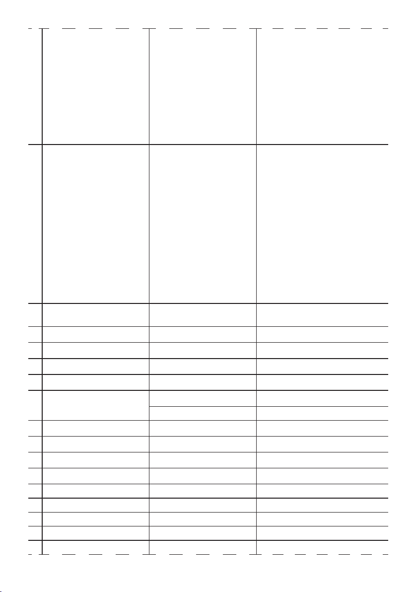
MENU*
1 DMX_START_ADDRESS 001 - 512
2 DMX_PERSONALITY 1:BASIC To choose the DMX mode.
2:STANDARD
3:EXTENDED
3 CURVE 0:LINEAR To choose the dimmer curve.
1:S-CURVE
2:SQUARE LAW
3:INVERSE SQUARE LAW
4 OUTPUT_RESPONSE_TIME 0:AUTO To choose the dimmer speed.
1:FAST
2:MEDUIM
3:SLOW
5 MODULATION_FREQUENCY 0:600Hz Select PWM frequency.
1:1200Hz
2:2000Hz
3:4000Hz
4:6000Hz
5:25kHZ
NOTE: the terms shown in BOLD indicates the default settings.
SPECIAL PIDs**
1DMX FAULT 0:BLACKOUT To choose the behaviour of fixture in case of
dmx signal lost.
1:HOLD
2:STAND ALONE
2MASTER/SLAVE 0:MST DMX Outputs dmx signal.
1:MST NO DMX Doesn't output dmx signal.
2:SLAVE Receive dmx signal.
3 STAND ALONE MODE 0:STATIC To use static color presets.
1:CCT To use white presets:
2:MACRO To use color gels. Please refer to DMX chart
for Gel numbers, listed on DMX value column.
3:RGBW
To use RAW color mixing. Red, Green, Blue
and White channel are available as single
custom pid as listed below.
PROLIGHTS - EclDisplay UNFC / EclDisplay DATFC18
4STATIC COLORS (0 - 14)To choose between static color presets.
0: R
1: G
2: B
3: W
4: GB
5: RB
6: RG
7: RGB
8: RW
9: GW
10: BW
11: RGW
12: RBW
13: GBW
14: RGBW
5WHITE PRESETS (0 - 20) To choose between cct white preset.
0: 2800K
1: 3000K
2: 3200K
3: 3400K
4: 3600K
5: 3800K
6: 4000K
7: 4200K
8: 4400K
9: 4600K
10: 4800K
11: 5000K
12: 5200K
13: 5400K
14: 5600K
15: 6000K
16: 6500K
17: 7000K
18: 8000K
19: 9000K
20: 10000K
6COLOR MACROS (0 - 255) To choose between color gels. Please refer to
DMX chart for Gel numbers, listed on DMX
value column.
7MANUAL RED (000 ÷ 255) Raw red channel (used in RGBW stand alone
mode).
8MANUAL GREEN (000 ÷ 255) Raw green channel (used in RGBW stand
alone mode).
9MANUAL BLUE (000 ÷ 255) Raw blue channel (used in RGBW stand alone
mode).
10 MANUAL WHITE (000 ÷ 255) Raw white channel (used in RGBW stand
alone mode).
11 FULL ON 0:HB MODE High Brightness Mode, delivering the full
output on every primary color
1:STUDIO MODE Fixture will reach 6000K white point.
12 STUDIO-RED (000 ÷ 255) Max value of red color intensity when all color
are at maximum value.
13 STUDIO-GREEN (000 ÷ 255) Max value of green color intensity when all
color are at maximum value.
14 STUDIO-BLUE (000 ÷ 255) Max value of blue color intensity when all
color are at maximum value.
15 STUDIO-WHITE (000 ÷ 255) Max value of white color intensity when all
color are at maximum value.
16 WHITE CALIBRATION-RED (125 ÷ 255) Max value of red color intensity.
17 WHITE CALIBRATION GREEN (125 ÷ 255) Max value of green color intensity.
18 WHITE CALIBRATION-BLUE (125 ÷ 255) Max value of blue color intensity.
19 WHITE CALIBRATION-WHITE (125 ÷ 255) Max value of white color intensity.
20 CURRENT HOURS (00000-65535) Shows fixture hours.
This manual suits for next models
2
Table of contents
Other PRO Light Spotlight manuals


