Pro's Kit MT-7071N User manual
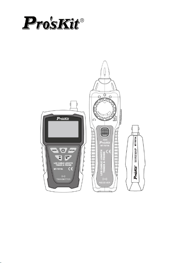
1
MT-7071N
LCD Cable Length Toner & Probe Kit
User’s Manual
1st Edition, 2023
©2023Copyright by Prokit’s Industries Co., Ltd.

2
1. OVERVIEW
Thank you for purchase Pro’sKit MT-7071N LCD Cable Length
Toner & Probe Kit. The Toner and Probe set is used to measure
cable length and quickly trace and identify cables or wires within a
group and also check the operation of telephone lines. With proper
use and care, this instrument will provide many years of reliable
service.
MT-7071N is a new high-frequency filter circuit technology, with the
elimination of noise and anti-interference line tracker, LCD display
screen. Users can select display language in Chinese or English.
Suitable for ordinary network, PoE network, UTP / STP cable search
and positioning. The interface on the network can be located through
the port flashing function. Network Cable and BNC coax map test.
This product can perform the network wire length testing. This
product is suitable for telecommunications, network communication,
monitoring, CATV and other indoor and outdoor wiring construction
or maintenance projects.
Caution
!This product uses 9V 6LR61 or 6F22 battery power supply, and
6LR61 battery is recommended.
!To save the battery, please shut down immediately after use. If it
is not in use for a long time, please remove the battery in the
transmitter and receiver to avoid damage to the product caused by
battery liquid from leaking out.
!This product is strictly prohibited to access the live lines above
voltage DC 60V or any AC voltage.
!Please do not perform related operations on the communication
line during thunderstorms to prevent lightning strikes and personal
safety.
!Do not place this product in dusty, wet and temperatures above
40℃.
!Please do not disassemble the device. Repair and maintenance
should be done by a professional staff.

3
2.Diagram
Transmitter and Remote Unit Diagram
① RJ45(with LED) connector:For Cable Length and Port Flash test
② RJ45 connector:For Cable map、Cable Tracing.
③ BNC connector: For Coax map、Coax Tracing
④ LCD display.
⑤ “ ” key:ENTER key: Press this key for a test choose or setting.
⑥ “ ” key:Press this key to move arrow cursor up or left on LCD
to choose function.
⑦ “ ” key:Press this key to return to previous menu.
⑧ “ ”:Press this key to power on, and long push again for power
off.
⑨ “ ”:Press this key to move arrow cursor down or right on LCD
to choose function.
⑩ Battery cover.

4
Receiver Diagram
① Probe:Used for cable tracing and NCV detection.
② LED light
③ Power ON/OFF indicator
④ NCV indicator
⑤ Signal status indicator
⑥ Sensitivity control
⑦ Earphone socket (Φ3.5mm)
⑧ Function switch (LED light/NCV/OFF/SCAN mode)
⑨ Speaker
⑩ Locating and tracing cables function button
⑪ RJ45(8 pin)/ RJ11 (6/4/2 pin) cable mapping test
socket.
⑫ Battery cover

5
3.Operation
Do not connect with DC voltage over 60V or any AC
voltage live circuit equipment or it will result damage.
Press “ ”key to power on, as show blow. Press“ ” or“ ”key
to choose function. Press“ ”key to test. Press“ ”key to return.
Note: The arrow “▲” on the LCD display indicates the test port
location of the network cable to be tested.
graph 1 graph 2
Graph 1: The cable shall be inserted into the middle RJ45 connector.
Graph 2: The cable shall be inserted into the left RJ45(with LED)
connector .
3.1 Cable map test:
Ø Insert the pending network cable into the transmitter RJ45 socket in
the middle and the other end into the receiver socket or remote unit,
BNC coax into BNC socket.
Ø Select the “CONT” menu and press “ ” to test with test results
shown below:
UTP STP
!"#$%
▲
Type:Ca t5e/6/6a
Press ENTER Test
▲
Type:Cat.5e/6/6a
Start Test
Un it : Meter
Le ngth

6
Short disconnection crossover
Ø Telephone cable test results shown below:
6p6c 6p4c 6p2c
Ø BNC coax test results shown below:
Ø If the display "cable open " indicates that the network jumper is all
open or the other end of the network cable is not inserted in the test
remote or receiver, or the test interface is wrong.
3.2 Measure Cable Length:
During the test, the power consumption is large and the
battery power decline is fast. the test time should be interval
until the battery power is restored.
Ø Insert the pending network cable into the transmitter socket in the
left. Do not plug in any socket at the other end.
Ø Select the “Length” menu and press “ ” to test with test results
shown below:
▲
CONT

7
Ø Units of length can select “Meter” “Yard” “Foot” under the Units
menu.
Ø Because each pair of wire has different twisted density, it is normal
to measure the numbers slightly different, which can be measured
many times to get the same measurement value.
Ø From the image, it means there exists problem at 12.1m. To make
sure it is short or broke there, you can test it continuity to know
details.
■ NOTE: Kind reminds when measuring cable length.
1. The network cable to be tested must be de-energized.
2. Disconnect the cable at the far end, no remote, no other
devices connected!
3. The range must be 2.5m—200m, otherwise , it would be
display 0 meter.
3.3 Cables tracking:
Ø Connect one end of the target cable to the RJ45 socket in the
middle of the transmitter, BNC coax into BNC socket.
Ø Select the “SCAN” menu and press “ ” to transmit and shown
below:
▲
Typ e:Cat.5e/6/6a
Start Te st
Un it : Meter
Le ngth
▲

8
Ø The receiver function switch is switched on to the "Scan" or
"lighting" position.
Ø The receiver sensitivity knob is rotated clockwise to the maximum
(the arrow tail is above).
Ø Press and hold the "SCAN" button in the middle of the receiver,
while the probe is close to the network cable to be measured, the
speaker emits a clear "beep-beep " sound, and the network cable
contacted by the receiver probe is the target network cable to find.
Ø When tracking a cable in the working network, due to the network
switch, there may be audio signals adjacent to the target cable,
each cable can be removed to find the target cable or try to rotate
the receiver sensitivity knob counterclockwise to reduce the
reception sensitivity to find the target cable.
3.4 Port Flash & Switch details testing:
This function transmits the pulsing signal through the transmitter to
flashing the LED indicator of the network switch, then can locate the
interface of the network cable on the switch. At the same time, the
network switch working performance can be tested.
Do not connect with DC voltage over 60V or any AC
voltage live circuit equipment or it will result damage.

9
Ø Insert the network cable into the transmitter socket in the left.
Ø Select the “Flash” menu and press “ ” to start testing.
Ø The 2 indicators on the RJ45 jack port will be lit and flash. Then
observe the ports on switch, if there is a port whose flash frequency
is 3 secs, and slower than all the other ports, it tells you the port is
target one you’re looking for.
Ø Also, the device can tell you the connected switch’s information,
such as its speed (10M/100M/1000M), transmitting modes (FDX:
full duplex/ HDX: half duplex) Protocol (Auto- Nego / Non-Auto-
Nego). See the graph for ref. as below.
Ø If "Check Port" is displayed, the reasons may be: 1. Network cable
insertion error and test interface; 2. Network cable is not connected
to the switch; 3. Network cable fault. 4. Switch, router fault or
incompatibility with the instrument. 5. This instrument fails.
3.5 Setting:
This function can set the language (Chinese / English), backlight time,
automatic shutdown time, contrast, etc.
Ø Select the “Setting” menu and press “ ” to start setting.
Ø Backlight setting:
Adjust the backlight time among 5S, 10S, 15S, on and off.
Ch eck Port
&'(()*+
,

10
Ø Auto-off time setting:
Adjust the Auto-off time among 15mins, 30mins, 1hour, off.
Ø Contrast setting:
Press the “ ” to setting. And press “ ” or “ ”
key to adjust the contrast to suit yourself.
Ø Version information:
To c he c k v e rs io n in f or ma t io n o f so ftw a re a n d ha r dw a re . a s a bo v e.
3.6 Non-contact Voltage detection (NCV)
This function is used to determine whether the wire or equipment has
an AC voltage, the detection range AC90-1000V (50 / 60Hz).
Ø Push the receiver function switch to the NCV position, put the
receiver probe close to the target body, if the AC voltage is
detected, the speaker emits an alarm sound of different frequency,
the speaker rapid sound indicates a high voltage or fire line, the
slow sound may be low voltage or zero line.
-
./0

11
Note:
l This function is for reference, the voltage may still remain even
there is no detection showed up. There are many possible
factors might block the detection.
l There are external sources (like flashlight and motor) may trigger
non-contact voltage detection.
3.7 Flashlight
Ø Push the receiver switch to the “ ” position, and the front LED
auxiliary lighting LED is turned on for lighting with insufficient light.
Ø Only for lighting in the case of insufficient light, do not use it for a
long time to save the battery.
4. Battery Replacement
Ø When the battery symbol on the transmitter display is low, replace
the battery. When the receiver power indicator flashes, the battery
is low, replace the battery.
Ø The battery is 6F22 or 6LR61 9V battery, and the better
performance 6LR61 alkaline battery is recommended.
Ø Turn off the Transmitter or Receiver and disconnect all test
leads before replacing the battery.
Ø Properly install in the case to power the Transmitter and
Receiver.

12
5. Accessories
Parts
QTY
Parts
QTY
Transmitter
1
RJ45—RJ45 Cable
2
Receiver
1
RJ45- alligator clips
1
Remote Unit
1
User Manual
1
Earphone
1
Storage bag
1
6.Specification
MT-7071N Transmitter Specifications
Display
LCD 128×64 Dots (50×27.5mm)
Language
Chinese、English
Connectors
RJ45 × 2,BNC × 1
Battery
9V: 6LR61 or 6F22
Cable Map
Cable Type
CAT.5E; CAT.6; CAT.6A; CAT.7
cable;Telephone cable;BNC coax
Max range
300m
Display
LCD: R&M 1-8/G
Cable Length
Measurement
Cable Type
CAT.5E; CAT.6;cable;Telephone
cable
Range
2.5m—200m
Unit
meters/ yards / feet, selectable
option
Accuracy
±5%
Cables
Tracing
Cable Type
CAT.5E; CAT.6; CAT.6A; CAT.7
cable; telephone cable;BNC coax
Scan range
600 m
Frequency
455KHz
Max.
Signal
9±1Vp-p

13
Voltage
Port Flash
Flash
frequency
3sec/time
Link test
10M/100M/1000M; FDX/HDX; Auto-
Nego/Non-Auto Nego.
Back Light
5s/10s/15s/on/off
Auto OFF
15min/30min/1 hour/off
Working
current
≤150mA
Protection
≤60V DC
Dimension
138 × 80 × 35mm
MT-7071N Receiver Specifications
Switch
4 positions
Key press
1
Response
frequency
455KHz
Sound dB
≥85dB
Receiver
signal
Elimination of noise
Tone mode
1 mode
Sensitivity
knob-operated control
Indicator
LED ×3
Flashlight
lighting
LED×1
Connectors
RJ45× 1
Earphone
jack
Φ3.5mm×1
Battery
9V: 6LR61 or 6F22
Working
≤100mA

14
current
Dimension
202 × 50 × 32mm
Remote Unit Specification
Connectors
RJ45× 1,BNC× 1
Dimension
106×32×30mm
7. MAINTENANCE & TROUBLE SHOOTING
Warning:
• Turn off the Transmitter or Receiver and disconnect all test leads
before replacing the battery.
Caution:
• To avoid damaging the case, do not use solvents or abrasive
cleansers. Clean the case with a soft cloth dampened with water or
a mild soap solution.
Trouble shooting
Possible Problems
Trouble shooting
The signal from
Transmitter can not be
detected by receiver
1. Shortage of battery power: Check
the battery on both Transmitter and
receiver. If the battery voltage is less
than 7.0V, please replace new battery
2. Make sure the switch position on
receiver is “SCAN” or “LED”. The
SCAN function will not work if the
switch is at “NCV” position.
3. Device damaged: please return the
product to the place you purchased
the product for maintenance
No signal received
from Transmitter on
Live
There might be conflict between the
signal from telephone office and the

15
telecommunication
device testing
signal from Transmitter. Please turn
off the telephone exchange device.
Incorrect cable
mapping result
LCD display broken: please return the
product to the place you purchased
the product for maintenance.
Improper connection of networking or
telephone cables: please reconnect
the cables to RJ45 or BNC individual
jacks.
Others
Device damaged: please return the
product to the place you purchased
the product for maintenance.

16
MT-7071N LCD 音頻線長查線器使用說明書
感謝購買和使⽤ MT-7071N LCD ⾳頻線⾧查線器,使⽤本儀器前請仔細
閱讀說明書並注意如下事項,閱後請妥善保存,以備⽇後查閱。
注意事項:
●本產品使⽤ 9V 6LR61 或 6F22 電池供電,推薦使⽤ 6LR61 電池。
●為節省電池,使⽤完畢請⽴即關機。如⾧時間不使⽤,請取出發射器
和接收器內的電池,以免電池漏液造成產品損壞。
●本產品嚴禁接⼊超過保護電壓 DC 60V 或任何交流電壓的帶電線路使⽤
●雷⾬天切勿進⾏通信線路操作,以防雷擊,造成設備或⼈⾝傷害。
●不要將此產品⾧時間暴露在陽光直射之下。
●不要將此產品放置在多塵、潮濕及超過 40℃溫度的地⽅。
●請勿隨便拆卸此產品,維修應由專業⼈員進⾏。
⼀、产品特点概述:
MT-7071N LCD ⾳頻線⾧查線器,LCD 液晶顯⽰,中⽂/英⽂語⾔選 擇
介⾯。具有抗⼲擾⾳頻尋線,對線測試(導通、 短路、斷路、交叉),
網線線⾧測試(2.5-200 ⽶),端⼜閃爍並檢測網絡交換機性能等功能;可
設置:背光點亮時間、⾃動關機時間、⾧度單位 ⽶/英呎/碼等,可以接
⼊普通網絡交換機、PoE 網絡交換機帶電尋線。本產品適⽤於網絡佈
線、網絡維護與故障排查等。

17
⼆、產品⽰意圖
發射器及測試遠端產品⽰意圖
① RJ45(帶LED)插座:網線線⾧測試、端⼜閃爍測試插座
② RJ45 插座:對線、尋線測試插座
③ BNC 同軸電纜尋線、對線測試插座
④ LCD 顯⽰屏
⑤ “ ” 鍵:確定(ENTER)鍵,按此鍵進⾏測試選擇或設定
⑥ “ ”鍵:向上或向左移動鍵
⑦ “ ”鍵:返回 RETURN 鍵
⑧ “ ”開/關機鍵:按此鍵,開機;⾧按此鍵,關機
⑨ “ ”鍵:向下或向右移動鍵
⑩ 電池蓋

18
發射器及測試遠端產品⽰意圖
① ⾳頻接收探頭
② 輔助照明LED
③ 電源指⽰燈
④ NCV ⾮接觸驗電指⽰燈
⑤ 尋線功能指⽰燈
⑥ 靈敏度調節旋鈕
⑦ ⽿機插座
⑧ 檔位開關:從上到下依次為 LED 照明/NCV/OFF/SCAN
⑨ 揚聲器
⑩ SCAN鍵:尋線時按住此鍵,接收信號,鬆開,不接收信號
⑪ RJ45:對線測試使⽤
⑫ 電池蓋

19
三、使⽤說明
按“ ”鍵開機,進⼊如下畫⾯,按“ ”或“ ”鍵選擇菜單,按
“”進⾏測試,按“ ”鍵返回。
注意:LCD 顯⽰屏上箭頭“▲”指⽰測試網線接插位置:
待測網線應插⼊中間插座 待測網線應插⼊左側插座
對線:⽤於檢測網絡跳線連接情況及連接故障判斷,如“斷路”“交叉”“短
路”等。
⾧度:⽤於檢測網線、電話線⾧度,測量範圍 2.5-200 ⽶,只需網線⼀端
插⼊發射器左側 RJ45 插座(①),另外⼀端不可連接測試遠端、接
收器或任何網絡接⼜,更不可帶電測量,否則可能燒毀儀器。
尋線:需配合⾳頻接收器⼀起使⽤,⽤於尋找⽬標網線。發射器發射⾳
頻信號,接收器接收信號。
閃爍:⽤於查找⽬標網線另外⼀端在交換機上對應的接⼜,發射信號使
交換機接⼜燈閃爍,同時測試交換機⼯作性能:10M/100M/1000M
半雙⼯/全雙⼯;⾃協商/⾮⾃協商等。
設置:設置發射器功能參數,可設置語⾔(中⽂/英⽂),背光時間,⾃
動關機時間,對⽐度等。
▲
类型:网络线
按下ENTER测试
▲

20
3.1 對線測試:
Ø 將待測網絡跳線或電話跳線兩端分別插⼊發射器中間 RJ45 插座(②)
和測試遠端或接收器 RJ45 插座;BNC 跳線插入 BNC 插座。
Ø ⾳頻發射器選擇“對線”菜單,然後按“ ”進⼊測試菜單,按“ ”或
“ ”鍵選擇測試類型,“網絡線 ”或“ BNC ”,確認後按“ ”進⾏測
試,測試結果如下圖顯⽰:
正常連接 UTP STP
短路 斷線 交叉
Ø 網絡跳線故障顯⽰,優先顯⽰短路狀況,當有短路故障時,斷線及交
叉故障不顯⽰,斷線和交叉故障可同時顯⽰。
Ø 電話線連接如下圖
6P6C 電話線 6P4C 電話線 6P2C 電話線
Ø BNC 線連接如下圖
Ø 如顯⽰“線纜開路或未連接”表⽰網絡跳線全部開路或者網線另外⼀端沒
▲
Table of contents
Languages:
Other Pro's Kit Test Equipment manuals

Pro's Kit
Pro's Kit MT-7071 User manual

Pro's Kit
Pro's Kit MT-7062 User manual

Pro's Kit
Pro's Kit MT-7801-FC User manual

Pro's Kit
Pro's Kit MT-7801 User manual

Pro's Kit
Pro's Kit MT-7076 User manual

Pro's Kit
Pro's Kit 8PK-4103IN User manual

Pro's Kit
Pro's Kit NT-305 User manual

Pro's Kit
Pro's Kit N2 Series User manual

Pro's Kit
Pro's Kit MT-8006B User manual

Pro's Kit
Pro's Kit MT-7063 User manual