pro user RVC3600 User manual

WIRELESS BACK
-
UP CAMERA SYSTEM
KABELLOSES RÜCKFAHR
-
KAMERA
-
SYSTEM
SYSTÈME DE CAMERA D
E RECUL SANS FIL
DRAADLOOS CAMERASYST
EEM
w ith 3 ,5
inch m onito r
m it 3 ,5
”
Monito r
a
ve c é cran 3 ,5
po uce s
m
e t
3 ,5
inch m
onitor
RVC3 6
0 0


INTRODUCTION
Ple a s e ca re fu lly re a d a n d fo llo w th e fo llo w in g s a fe t y a nd o p e ra t in g
in s t ru ct io n s .
IMPORTANT SAFETY INSTRUCTIONS
Be fo re Yo u In s ta ll
In te rfe re n ce
Re p a ir
PARTS
The Pro
-
User
RVC3600
is member of the family of advanced
car back
-
up systems
manufactured by Pro User International Ltd.
The Pro
-
User Wireless Back
-
up Camera and Monitor, when used as described, will
improve your ability to see behi
nd your car, camper, trailer, or mini
-
van. We have taken
numerous measures in quality control to ensure that your product arrives in top condition,
and will perform to your satisfaction.
If you are not confident working with 12 volt DC vehicle wiring, removing and reinstalling
interior panels, carpeting, dashboards or other components of your vehicle, contact the
vehicle’s m
anufacturer, or consider hav
ing the camera system professionally installed.
This device, as well as all other wireless devices, may be subject to interference.
Interference may be caused by cell phones, Bluetooth headsets, Wi
-
FI routers, pow
er
lines and other various electrical equipment, etc.
The
camera system
should not be opened. Any attempt at modification or repair by the
user will
entail the loss of your guarantee.
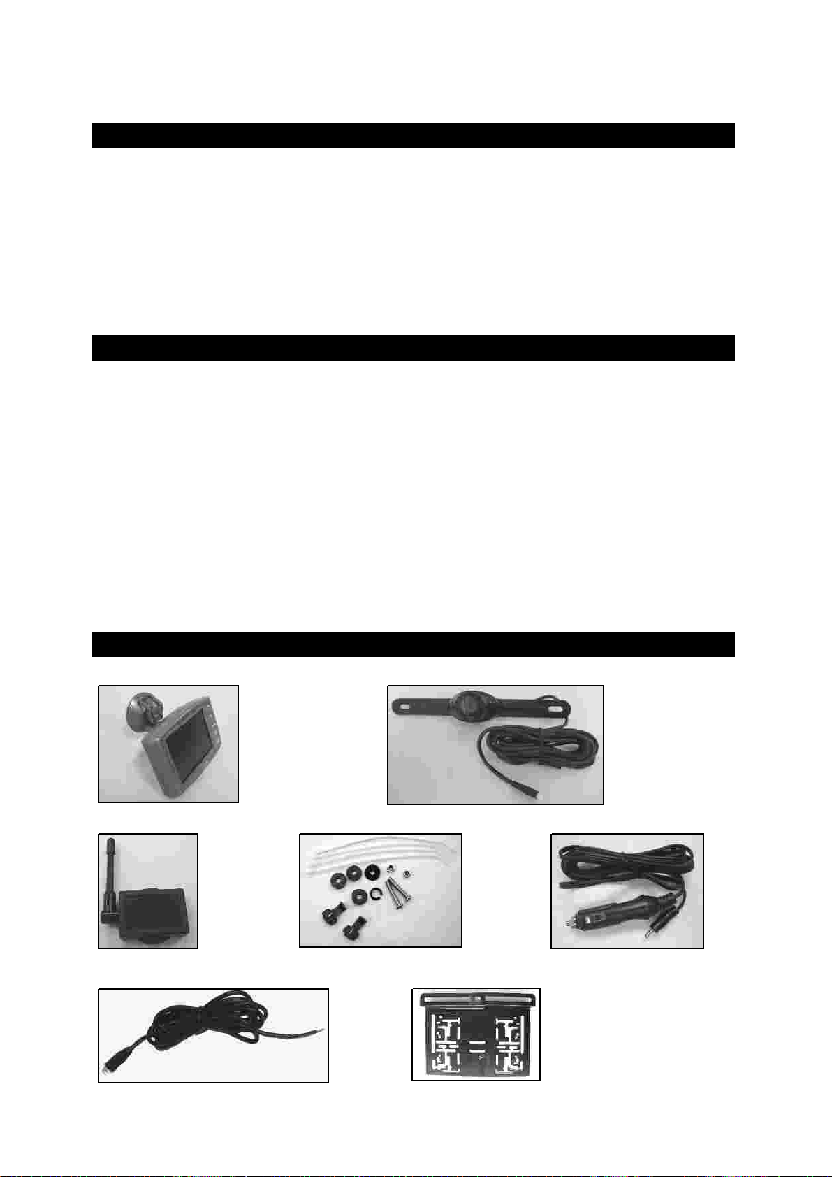
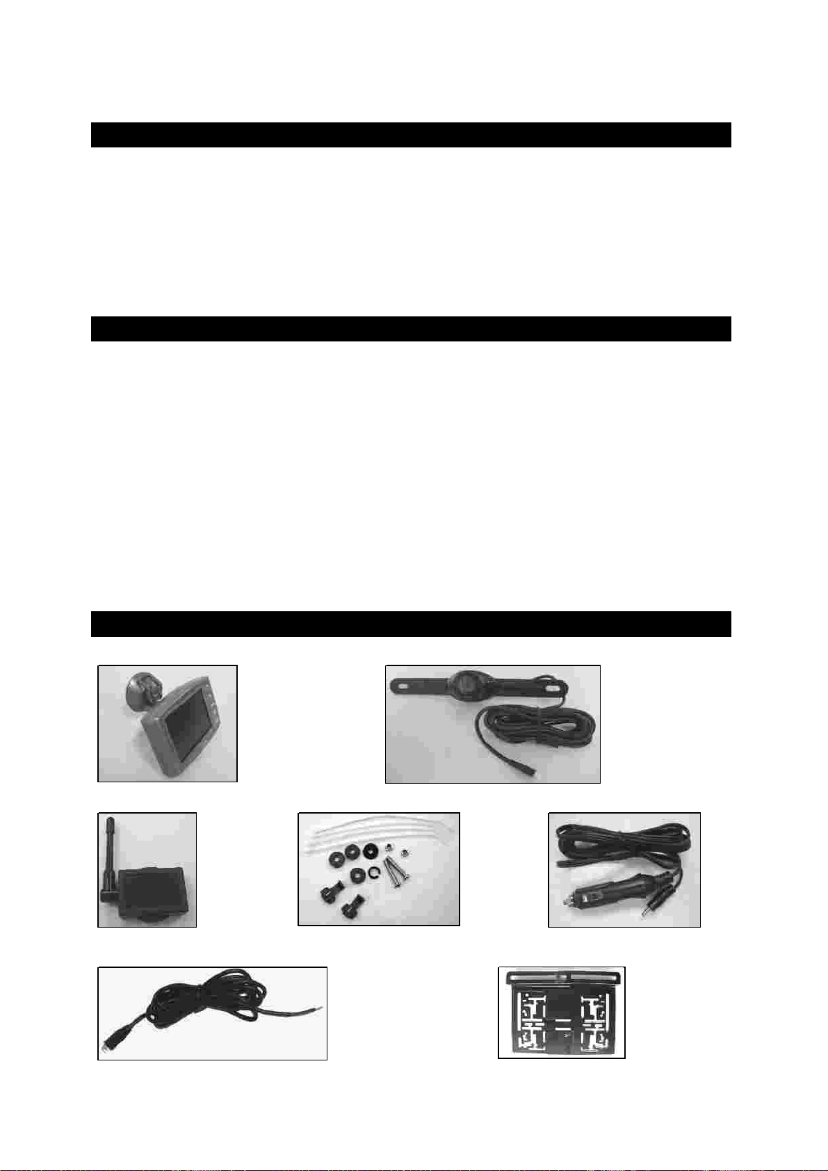
1. Monitor and mounting Arm
2. Camera + Power Cable
3. Transmitter Box
4. Mounting Accessories
5. Monitor Power Cable
6. Transmitter Box Power Cable
7
.
Camera mounting
-
plate
INSTALLATION
Th e s e in s t ru ctio n s d o n o t a p p ly t o a ll v e h icle s . Th e y a re o n ly m e a nt a s a g e n e ra l
g u id
e du e to t h e nu m b e r o f d iffe re nt m a ke s & m o d e ls .
Fo r v e h icle s p e cific
q u e s t io n s co n t a ct y o u r v e h icle ’s m a n u fa ctu re r.
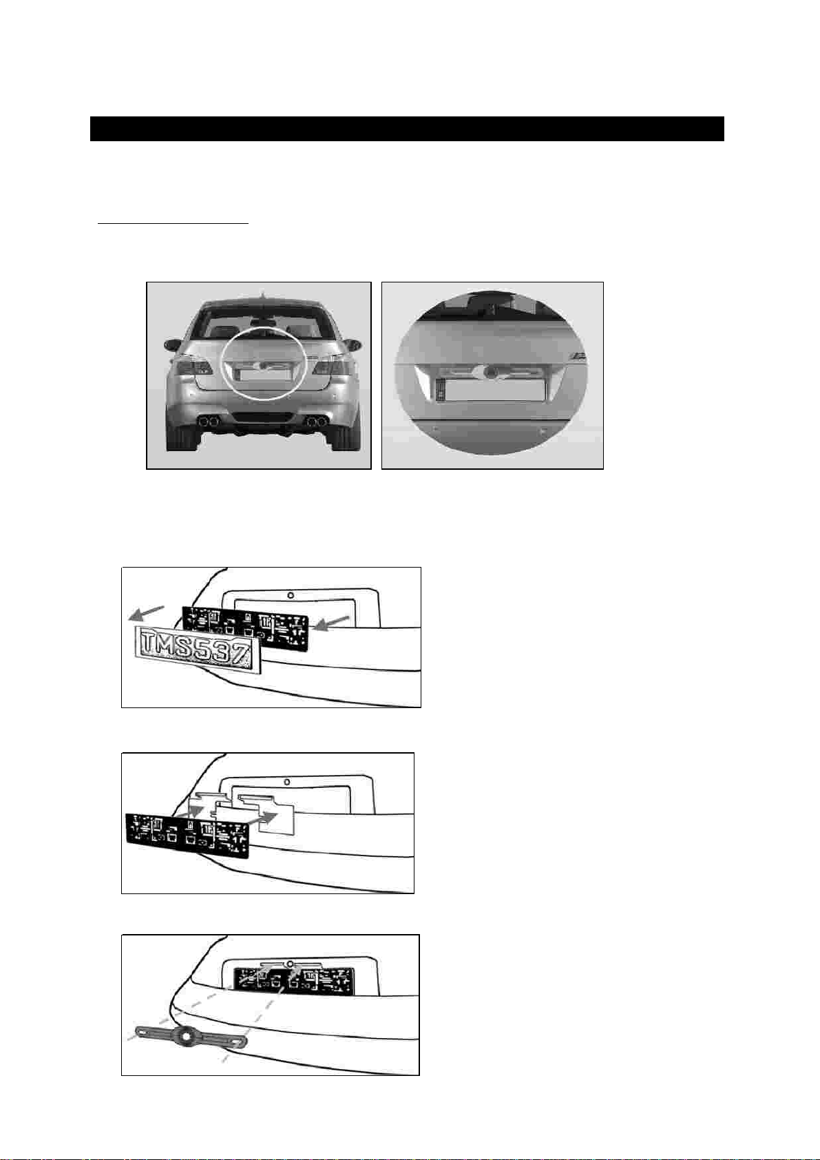
Ca m e ra in s t a lla t io n
There are several ways to mount the camera on the back of your car. But the most
convenient is to mount it near the li
cense plate of the car. Supplied are two mounting
plates that can be fixed behind the license plate. On these plates the camera can be fixed.
At some type of cars it is not possible to mount the camera
near
the license plate. You
may have to
find another spot at the back of your car to mount the camera with the
supplied bolts and screws.
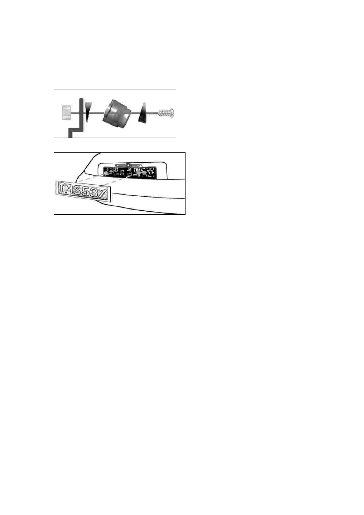
1.
Loosen the license plate bolts/screws, and then remove the rear license plate.
2.
Position the supplied mounting plates behind the license plate brack
et. Secure both
license plate bracket and mounting plates with the lic ate bracket bolts/screws
.
3.
Fix the camera with the supplied bolts and nuts in the mounting plates. Align the
camera left/right and tighten the screws/bolts.
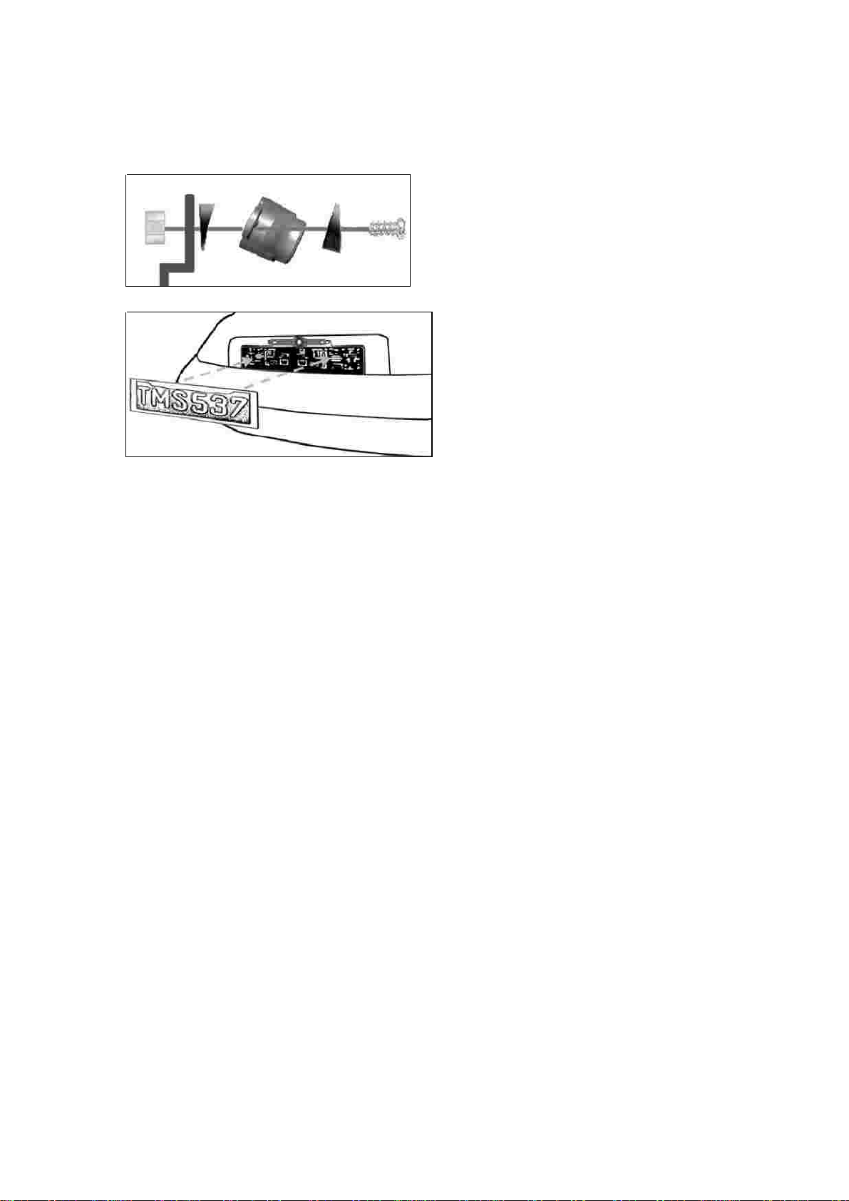
If
you want the camera to be angled down, use the supplied wedges between the
camera and the mounting plates as shown in the picture.
4.
Mount the license plate on the license plate bracket.
5.
Choose a routing path
for the camera’s power cable t
hrough the vehicle’s body to the
reverse light circuit.
If in doubt, seek professional installation assistance.
Some vehicles may have a hole available to pass the wire through, such as where the
license plate light is mounted, or you can drill a hol s
e to where the power cable
is attached to the camera. Once you have chosen where the cable will enter the
vehicle’s body, remove the camera.
7.
Before you drill a hole you MUST CHECK and se
e WHAT IS BEHIND WHERE YOU ARE
DRILLING. If there are any vehicle components, such as electrical parts or fuel
system components behind where you are drilling, you must take whatever
precaution is necessary not to damage them. Remove the license plate and
camera
before drilling.
8.
After you have drilled the
hole, insert the supplied grommet, then pass the camera
cables through the grommet into the vehicle. You must use the grommet to prevent
the metal edge of the hole from cutting the camera cable.
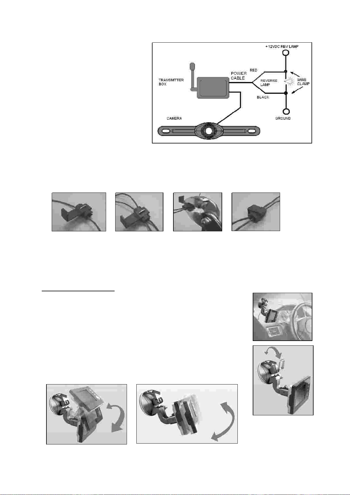
9.
Mount the
transmitter box inside the trunk. Connect the camera’s power cable and
the transmitter box power cable to the transmitter box.
10.
Next you’ll need to find the vehicle’s reverse lights. Turn the vehicle’s ignition key to
the accessory position, engage the park
ing brake and put the car in reverse. Look at
the vehicle’s tail lights to see where the reverse lights are located, they are the white
lights.
To locate the reverse light’s 12V+ wire it will be nec ry to gain access to
the rear of the vehicle’s tail li
ght. For help locating the vehicle’s reverse light circuit
contact your vehicle’s manufacturer for vehicle specific wiring diagrams.
11.
Once you have located the reverse light circuit you will have to route the transmitter
box power cable to that location. Y
ou must securely fasten the power cable to prevent
it from being caught on any vehicle component such as the trunk hinge.
route
the cable on the outside of the vehicle!
6.
If you are able to use an e xisting ope ning, skip
the ne x t tw o ste ps .
Ne v e r
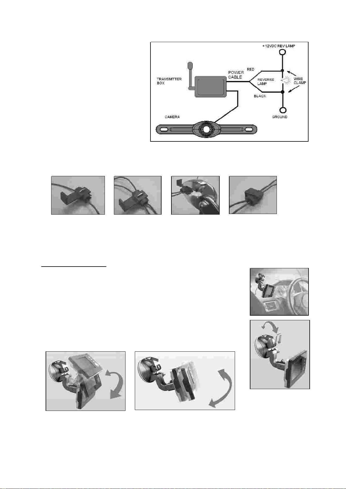
12.
The reverse light sockets on
most vehicles have two wires
connected to them. Us
ually the
negative wire is black and the
positive wire is a colored wire.
If you are uncertain about the
wiring, you can use a 12 volt
multimeter available at most
auto parts stores to determine
which is the positive wire.
Follow the manufacturer’s
instruc
tions for the safe use of
the multimeter.
13.
After determining which wire is
the positive and which is the
negative, turn off the ignition key, then remove the battery’s negative cable.
14.
Splice the red wire using the supplied in
-
line wire connectors to the rev
erse light’s
positive (+) wire. Use a set of slip joint pliers to squeeze the TAP and insure good
connection.
15.
Next splice the black wire of the transmitter box powe e to the reverse light’s
negative (
-
) wire or ground.
16.
Replace the reverse light
bulb, and then re
-
install the light socket. Secure all the
wires with cable ties or electrical tape.
17.
Re
-
attach the negative battery cable to the battery.
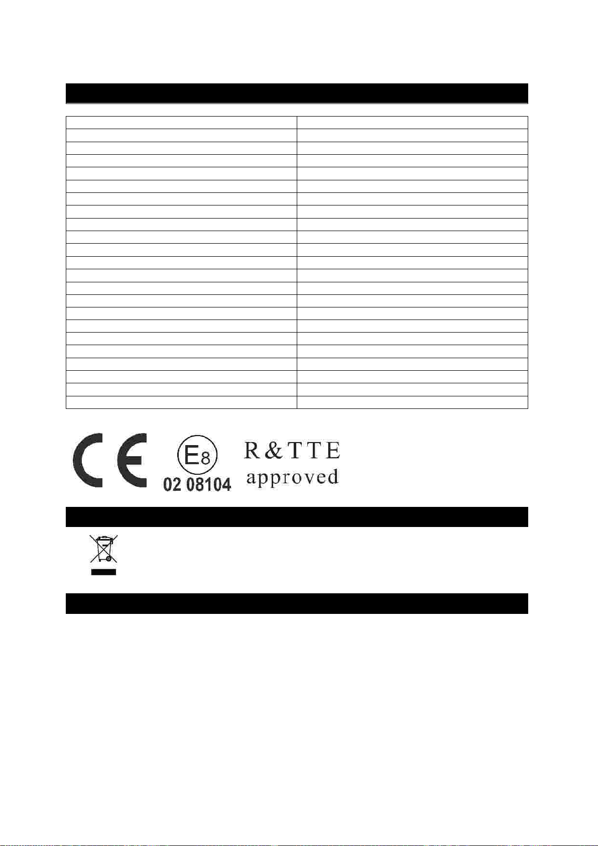
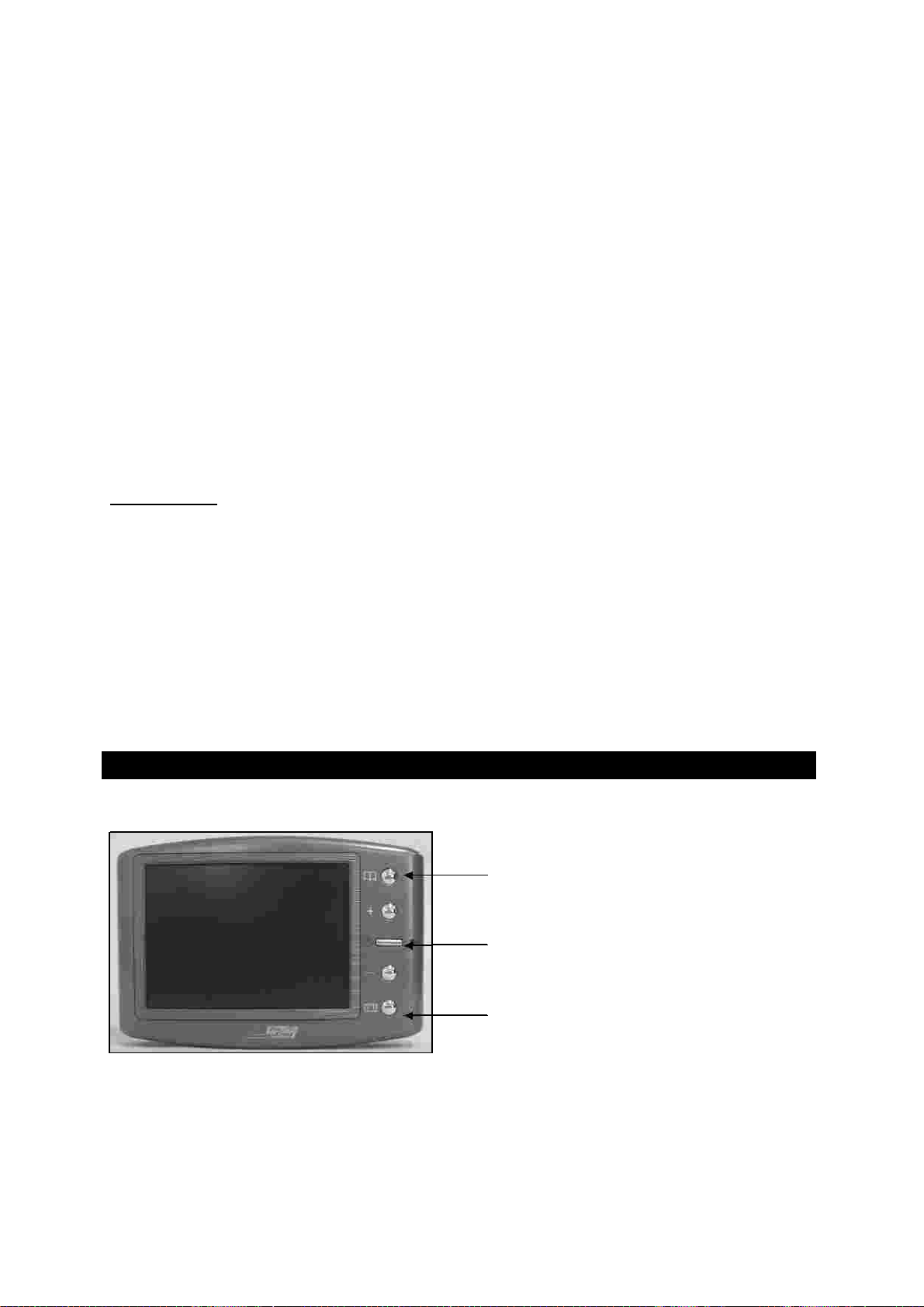
When choosing a location to mount the monitor, make sure the
monitor is in an
area that will not obstruct your vision while driving.
1.
Before mounting the monitor, clean the mounting surface well.
2.
Position the suction mount to the smooth surface which suits
your requirement.
3.
Press the suction cap against the smooth surface
and p
res
s the
lock down to attach and fix the mount to the surface.
4.
Snap in the monitor to the suction mount.
5.
Adjust the mounting arms to suit your view angle to the monitor
and tighten the screws on the mount to fix the position.
6.
Route the power cable to t
he vehicle’s cigarette lighter socket/12V power outlet. The
cable must not interfere with the safe operation of
the vehicle.
7.
Insert the small 12 Volt DC plug of the power cable into the right side of the monitor.
8.
Plug the 12 Volt cigarette lighter
plug
int
o the vehicle’s cigarette lighter socket.
Mo n it o r I ns ta lla t io n

9.
Press the ON/OFF button to turn the monitor ON.
To maximize the effectiveness of the suction mo
unt, it is recommended that the
ap
plication be performed under the following conditions:
Surface t
emperature should
be between 21 and 38 degrees Celsius
.
Application below 10
degrees
should be avoided.
Application should not occur in direct sunlight.
Mounting should be protected from exposure to direct sunlight for a period of 24 hours.
: UNDER EXTREME BRIGHT LIG
HT CONDITIONS, THE SCREEN IMAGE MAY TAKE A
FEW SECONDS TO STABLIZE. PLEASE WAIT UNTIL THE IMAGE HAS STABLIZED BEFORE
BACKING UP.
1.
Reattach the vehicle’s negative battery cable.
2.
Turn the ignition key to the accessory position, do not start th
e vehicle.
3.
Engage the parking brake, and then put the shifter in the reverse position.
4.
Turn the monitor ON by pressing the ON/OFF button on the monitor.
5.
Look at the monitor, if the image does not match your rear view mirror press the
Image Orientation butt
on on the monitor to correct the image.
6.
After testing the unit and you are satisfied with the route you have chosen for the
cabling, you must permanently install it.
7.
Route all wires behind interior panels or under carpeting so they are hidden.
Use
supplied
cable ties to neatly gather any excess wire.
•
•
•
NOTE
S y s t e m t e s tin g

OPERATION
Po w e r b u tt o n
Me n u b ut to n
Brig htn e s s
co n t ra
s
t
co lo u r
d ire c tio n
+
–
d ire ct io n
+
-
e x it
Gu id e lin e
b ut to n
The monitor will automatically turn on when the vehicle is in reverse gear.
There are 5 control buttons available for users to have their controls:
Press the POWER
button to supply power to the monitor. When the monitor image is on,
the blue LED will be lit. If
there is power to the monitor, but the monitor
image is OFF,
the blue LED will blink on and off. When the monitor power is off, no picture can appear
on the
screen and the blue LED will be off.
Press the Menu button to enter the menu screen as shown below:
Repeat pressing the Menu button to select
,
,
or
of the picture.
Press the + button or
–
button to adjust
settings within the
control selected. Press the
button to increase the value and
press the
button to decrease the value.
To change the orientation of the screen image, press the menu button until
is
selected. By pressing the
or
butto
n repeatedly, different screen orientations will be
available. These different views allow you to
mount the camera and monitor in any
position with keeping the right picture on the
monitor.
To exit the menu screen, select
on the screen.
This camera system has the option to show distance
-
guidelines on the display. This helps you to visually see
the distance between the objects behind your car. By
pressing the guideline button, you can switch this option
on and off.
Power button
Menu button
Guideline bu
tton
TECHNICAL SP
ECI FICATIONS
Ca m e ra
W ire le s s tra ns m itte r
LCD m o n it o r
ENVIRONMENTAL PROTECTION
WARRANTY
Operating Voltage
12V DC
Current consumption
<150mA
Image sensor
CMOS
No. of pixel
640x480
Resolution
>350
Optical lens
2,4mm / F2,0
Camera view angle
110 degree
Transmission frequency
2414MHz
RF tr
ansmission distance (open space)
>60M
Operation Voltage
12V DC
Standby Current
<25mA
Operation Current
<300mA
LCD display screen size
3,5inch
No. of pixel
480x234
Viewing angle
90 degree
Operation temperature
-
10 to +45 degree Ce
lsius
Storage temperature
-
30 to +80 degree Celsius
Waste electrical products should not be disposed of with household
waste.
Please recycle where facilities exist. Check with your local
authority or
retailer for recy
cling advice.
Pro
-
User warrants this product for a period of 2 years from the date of purchase to the
original purchaser. Warranty is not transferable. Warr ainst
workmanship and materials only. To obtain warranty service, pl
ease return the unit to
the place of purchase or authorized Pro
-
User dealer together with your proof of purchase.
The warranty is void if the product has been damaged or not used as described in this
manual. Warranty is void if a non
-
authorized repair has
been performed. Pro
-
User makes
no other warranty expressed or implied. Pro
-
User is only responsible for repair or
replacement (at Pro
-
Users’ Discretion) of the defective product and is not responsible for
any consequential damage or inconvenience caused by
the defect.
EINLEITUNG
Bitte le s e n S ie d ie Be d ie n un g s a n le it un g s o rg fä ltig d u rch u n
d fo lg e n S ie d e n
S ich e rh e it s h in w e is e n u n d d e r Mo n tag e a n le itu n g .
WICHTIGE SICHERHEITSHINWEISE
Vo r d e r Mo n ta g e
S tö ru n g
Re p a ra t u r
ZUBEHÖR
Der Artikel Pro
-
Us
er
RVC3600
gehört zur Familie der zukunftsweisenden Auto
-
Rückfahr
-
Kamera
-
Systeme der Firma Pro
-
User
-
International Ltd.
Die kabellose Pro User Rückfahr
-
Kamera mit Monitor ermöglicht es Ihnen bei
ordnungsgemäßer
Bedienung, hinter Ihr Auto, Ihren Anhänger oder Mini
-
Van zu sehen.
Es wurden zahlreiche Maßnahmen bei der Qualitätskontrolle ergriffen, um Ihnen ein Top
Produkt zu Ihrer Zufriedenheit zu liefern.
Falls Sie sich nicht sicher fühlen, dieses System an die 12V Stromversorgung Ihres
Fahrzeuges selbstständig zu montieren (bohren von Löchern, abn
ehmen von
Verkleidungen etc.)
nehmen Sie Kontakt zu Ihrem Autohaus oder zur Kfz
-
Werkstatt Ihres
Vertrauens auf. Dort können Sie eine professionelle Montage des Systems in Auftrag
geben.
Dieses Kamera
-
System kann, genau wie andere kabellosen System
e, bestimmten
Störungen unterliegen. Störungen können verursacht werden durch Handys, Bluetooth,
Headsets, Navigationssysteme und anderen elektrischen Geräten.
Dieses Kamera
-
System darf nicht geöffnet werden! Bei jeglichem Versuch einer
Reparatu
r erlischt die Garantie.
1.
Monitor mit Befestigungsarm
2.
Kamera und Kabel
3.
Sender
4.
Installations
-
Material
5.
12V Kabel für Monitor
6.
Netzkabel für Sender
7.
Befestigungsplatte für Kamera

MONTAGE
Die s e Be d
ie n u n g s a n le itu n g is t n ich t fü r a lle Fa h rz e ug e a n z u w e nd e n.
S ie is t e in
g e ne re lle r Le itfa de n fü r d ie m e is te n Fah rz e ug e . Be i fa h rz e u g s pe z ifis ch e n Fra g e n
w e n d e n S ie s ich b it te an Ih re n Fa h rz e ug h e rs t e lle r.
Mo n t a g e d e r Ka m e ra
Es gibt verschiedene Möglichkeiten,
die Kamera an der Rückseite Ihres Fahrzeuges zu
befestigen. die Gebräuchlichste ist, die Kamera nahe dem Nummernschild zu befestigen.
Sie können die mitgelieferten Montageplatten hinter dem Nummernschild befestigen. Auf
diesen Montageplatten können Sie nu
n die Kamera montieren.
Bei manchen Fahrzeugen ist es leider nicht möglich, die Kamera nahe dem
Nummernschild zu befestigen. Suchen Sie sich eine ande e am Heck Ihres Autos
und befestigen Sie die Kamera mit den mitgelieferten Schrauben
und Muttern.
1.
Lösen Sie die Schrauben des Nummernschildes und Nummernschildhalters und
nehmen beides ab.
2.
Positionieren Sie die Befestigungsplatten hinter dem Nummernschildhalter
und
befestigen Sie die Befestigungsplatten und den Nummernschildhal
ter wieder am
Fahrzeug.
3.
Befestigen Sie die Kamera mit die mitgelieferten Schrauben und Muttern an den
Befestigungsplatten.
Richten Sie die Kamera aus und ziehen Sie die Schrauben an.
Falls Sie die Kamera nach unten
abgewinkelt anbringen
möchten, benutzen Sie bitte
die beigefügten Keile zwischen Kamera und Befestigungsplatten (siehe Bild).
4.
Befestigen Sie nun Ihr Nummernschild wieder auf dem Nummernschildhalter.
5.
Wählen Sie jetzt eine Stelle, wo Sie das Elektrokabel der Ka
mera durch die Karosserie
Ihres Autos zum Stromkabel des Rückfahrlichtes ziehen können.
6.
Einige Autos haben in der Nähe des Kennzeichens eine Bohrung, wo Sie das Kabel
durchziehen können. Falls das nicht der Fall ist, müssen Sie in der Nähe des
Kennzeichens
, dicht an der Stelle, wo sich das Kabel der Kamera befindet, selber ein
Loch bohren. Wenn Sie den Platz für das Bohrloch festgelegt haben
können Sie die
Kamera und das Kennzeichen wieder demontieren.
7.
Bevor Sie bohren, demontieren Sie die Kamera und das Nummernschild.
PRÜFEN SIE,
BEVOR SIE BOHREN, WAS SICH AUF DER RÜCKSEITE DER STELLE BEFINDET, WO
SIE BOHREN WOLLEN! Sorgen Sie z.B. dafür, dass sich dort keine Ele
ktrokabel,
Flüssigkeitstanks oder Leitungen befinden. Beachten Sie alle Vorsichtsmaßnahmen!
8.
Nachdem Sie gebohrt haben, befestigen Sie den mitgelieferten Kantenschutz
in der
Bohrung,
um das Kabel vor den scharfen Rändern des Bohrloches zu schützen. Dann
zie
hen Sie das Kabel der Kamera ins Fahrzeuginnere.
9.
Befestigen Sie den Sender im Kofferraum.
Verbinden Sie das Kabel der Kamera
und
das Kabel des Senders mit dem Sender.
10.
Schalten Sie die Zündung Ihres Auto an (nicht starten!),
ziehen Sie die Handbremse
an und
legen Sie den Rückwärtsgang ein. Dann schauen Sie am Heck Ihres Autos, wo
sich der Rückfahrscheinwerfer befindet. Um die Kabel vom Rückfahrscheinwerfer zu
finden, müssen Sie die Rückseite der Heckbeleuchtung öffnen und die
entsprechenden Kabel orten. Ggf.
suchen Sie hierzu Ihr Autohaus oder die Kfz
-
Werkstatt Ihres Vertrauens auf.
11.
Wenn Sie die entsprechenden Kabel gefunden haben, legen
Sie das Kabel des
Senders an den Verbindungspunkt
. Sorgen Sie bitte dafür, das die Befestigung des
Kabels sicher und fest i
st, damit es beim Öffnen und Schließen der Heckklappe nicht
beschädigt werden kann. Verlegen Sie das Kabel
außerhalb
des Autos!
We nn S ie e ine vorhande ne
Öffnung be nutze n, könne n S ie d
ie zw e i folge nde n S chritte übe rspringe n.
n ie m a ls
12.
An der Kontaktdose des
Rückfahrscheinwerfers sind
zwei Drähte befestigt.
Meistens
ist der negative Draht schwarz
und d
er positive farbig. Wenn
Sie unsicher sind, können Sie
mit einem 12 V Multimeter (im
Fachhandel erhältlich) prüfen,
welcher Draht positiv bzw.
negativ ist. Folgen Sie der
Bedienungsanleitung des
Multimeters für den sicheren
Gebrauch.
13.
Wenn Sie festgestellt
haben,
welcher Draht positiv bzw.
negativ ist, schalten Sie die Zündung aus und entfernen Sie das negative Kabel Ihrer
Autobatterie. So ist sichergestellt, das kein Strom auf den Drähten ist.
14.
Verbinden Sie den roten Draht vom Kabel des Senders mit dem posi
tive Draht des
Rückfahrscheinwerfers.
Benutzen Sie dazu die beiliegenden Kabelklemmen. Drücken
Sie die Klemmen fest mit einer Zange zusammen und clipsen Sie die rote
Plastikabdeckung über diese Kontaktstellen.
15.
Verbinden Sie nun den schwarzen Draht de
s Sender
-
Kabels mit dem negative Draht
des Rückfahrscheinwerfers.
(Benutzen Sie auch hier die Kabelklemmen)
16.
Verschließen Sie die Heckleuchte wieder (achten Sie darauf, das
s
die Glühlampe
eingesetzt ist). Benutzen Sie Kabelbinder und speziell es (für
Ka
belverbindungen), damit alle Drähte und Kabel sicher und fest verlegt sind!
17.
Schließen Sie das negative Kabel Ihrer Autobatterie wieder an.
1.
Reinigen Sie die Stelle gründlich vor der Befestigung
2.
Positionieren Sie den Sauger auf der von Ihnen gewählten Fläche
3.
Pressen Sie den Sauger fest auf die gereinigte Oberfläche und
legen Sie d
en Hebel um damit der Sauger sicher und fest sitzt.
4.
Schieben Sie den Monitor in die am Sauger befindliche Halterung.
5.
Drehen Sie den Arm der Halterung und richten Sie den Bildschirm
in die gewünschte Position aus. Drehen Sie nun die Schrauben an.
Mo n t a g e d e s Mo n ito rs
W e n n S ie de n p a s s e n d e n Pla tz z u r Be fe s t ig un g d e s Mo n it o rs
g e fu nd e n h abe n , ve rg e w is se rn S ie s ic
h , d a s Ih n e n n ic h t d ie
S ich t v e rs p e rrt w ird w ä h re n d de r Fa h rt .
6.
Le
gen Sie das Netzkabel zum Zigarettenanzünder. Verlegen Sie das Kabel so, das es
zu keinen Einschränkungen oder Behinderungen während der Fahrt kommen kann.
7.
Stecken Sie den kleinen 12V Stecker von dem Netzkabel in die Öffnung auf der
rechten Seite vom Monit
or.
8.
Den anderen Stecker des Kabels stecken Sie in den Zigarettenanzünder.
9.
Drücken Sie auf den ON/OFF Schalter um den Monitor einzuschalten.
Um den festen Halt des Saugers zu gewährleisten wird der Gebrauch nur unter
Einhaltung folgender Voraussetzungen em
pfohlen:
Die Temperatur der Oberfläche sollte zwischen 21 und 3 egen.
Der Gebrauch unter 10 Grad Celsius sollte vermieden werden.
Der Gebrauch bei direkter Sonneneinstrahlung sollte vermieden werden.
Die Befestigung sollte vor direkter Son
neneinstrahlung geschützt werden.
1.
P
rüfen Sie, ob Sie das negative Kabel der Autobatterie wieder befestigt haben.
2.
Schalten Sie die Zündung Ihres Autos an (bitte nicht starten)
3.
Ziehen Sie die Handbremse an und legen Sie den Rückwärtsgang ein.
4.
Schalten Sie den Monitor mit dem ON/OFF Schalter a
n.
5.
Schauen Sie auf den Monitor. Wenn dieses Bild nicht identisch ist mit dem Bild, was
Sie im Rückspiegel sehen, drücken Sie den Bild
-
Orientierungs (Image Orientation)
Knopf am Monitor um das Bild zu korrigieren.
6.
Nachdem Sie den Test zur Zufriedenheit been
det haben verlegen Sie alle noch frei
liegenden Kabel.
7.
Verlegen Sie nun alle Kabel hinter den Fahrzeugverkleidungen oder unter den
Fahrzeugteppichen, so daß sie nicht mehr sichtbar sind.
Gebrauchen Sie die
beiliegenden Kabelbinder um die Kabel ordentlich z
usammen zu binden.
Der Monitor schaltet sich automatisch an, wenn der Rückwärtsgang eingelegt wird.
Des
Weiteren sind 5 Kontrollknöpfe am Monitor vorhanden.
Drücken Sie den Power Schalter um den Monitor mit St
rom zu versorgen.
Wenn das Bild
da ist, leuchtet die blaue LED auf. Wenn der Monitor Strom hat, aber das Bild ausgestellt
ist, blinkt die blaue LED.
Power Schalter
Menu Schalter
Hinweis Schalter
•
•
•
ACHTUN G: BEI EXTREM HELLEN LICHTVERHÄLTN IS S EN BEN ÖTIGT DER
MON ITOR EIN IGE S EKUN DEN UM S I CH DI ES EN LI CHTVERHÄLTN IS S EN
AN ZUPAS S EN . W ARTEN S I E BI TTE MI T D EM RÜCKW ÄRTS FAHREN BI S S ICH DAS
BILD S TABI LIS I ERT HAT.
S ys te m Te s t
BEDIENUNG
Po w e r S ch a lt e r

Me n u
S ch a lte r
He llig ke it
)
Ko n t ra s t
Fa rb e
Au s rich t u n g
Dire ctio n
EXIT
Hin w e is
-
S ch a lte
r
Wenn Sie den Schalter „Menu“ drücken, erscheint auf dem Monitor wie folgt
:
Drücken Sie de
n “Menu” Schalter wiederholt um
(brightness
,
(contrast)
,
(Color)
oder
(Direction)
des Bildes einzustellen.
Drücken Sie “+” oder “
-
“um die Einstellungen zu korrigieren
.
Mit „+“ erhöhen Sie die Einstellung, mit “
-
„ verr
ingern Sie die
Einstellung.
Um die Ausrichtung des Monitor
-
Bildes zu ändern, drücken Sie den “Menu” Schalter bis
“
” erscheint.
Wenn Sie jetzt „+“ oder „
-
„ wiederholt drücken, sind mehrere
Bildschirm
-
Einstellungen verfügbar. Die
verschiedenen A
nsichten ermöglichen es
Ihnen, die Kamera und den Monitor in jeder
Position zu befestigen und stets das richtige
Bild auf dem Monitor zu sehen.
Um das “Menu” zu verlassen, wählen Sie “
” auf dem Bildschirm.
d
ieses Kamera Sys
tem hat
die Option, Ihnen einen
Ab
stands
-
Hinweis auf dem Display
anzuzeigen.
Hier
können Sie
visuell den Abstand zwischen dem Objekt
hinter Ihrem Fahrzeug und Ihrem Fah
rzeug erkennen.
Mit Druck auf de
n „Hinweis“ Schalter können Sie diese
Option an
-
und ausschalte
n.

TECHNISCHE SPEZI FI KATION
K
a m e ra
Ka b e llo s e r Tra n s m it te r
LCD
M
o n ito r
UMWELTSCHUTZ
GARANTIE
Betriebsspannung
12V DC
Stromverbrauch
<150mA
Bildaufnahme
CMOS
Pixel
640x480
Bildauflösung
>350
Linse
2,4mm / F2,0
Blickwinkel
110 Grad
Übertragungsfrequenz
2414MHz
Übertragungsd
istanz (ohne Hindernisse)
>60M
Betriebsspannung
12V DC
Stromverbrauch min.
<25mA
Stromverbrauch max.
<300mA
Sichtbarer LCD Monitor
3,5Inch
Pixel
480x234
Blickwinkel
90 Grad
Betriebstemperatur
-
10° bis +45° Grad Celsius
Lagerungs
temperatur
-
30° bis +80° Grad Celsius
Unbrauchbare oder defekte elektronische Produkte dürfen nicht mit dem
Hausmüll entsorgt worden. Bitte entsorgen Sie diese Ge an den dafür
vorgesehenen Entsorgungsstellen oder fragen Sie Ihr
en Fachhändler.
Pro User gewährt eine Garantie von 2 Jahren ab Kaufdatum.
Die Garantie ist nicht
übertragbar. Garantie wird gewährt auf Verarbeitungsmängel und Materialschäden. In
Garantiefällen senden Sie bitte das Gerät mit dem Kaufbeleg an I
hren Händler oder an
einen
autorisierten
Pro User Vertreter. Die Garantie erlischt, wenn das Gerät beschädigt
wurde, wenn Bedienungsfehler vorliegen oder bei unfachmännischer Reparatur durch
nicht
autorisierte
Personen.
Bei anerkannter Garantie wird Pro Us
er das Gerät reparieren
oder Ersatz leisten. Pro User ist nicht verantwortlich zu machen für Folgeschäden oder
sonstige Unannehmlichkeiten.
INTRODUCTION
S ’il v o u s p la it , v e u ille z lire a t te n t iv e m e n t c e tt e n ot ic e e t s u iv re le s in s t ru ct io n .
IMPORTANT
-
CONSIGNES DE SECURIT
E
Av a n t l’in s t a lla tio n
In te rfé re n ce
Ré p a ra tio n
CONTENU
Le Pro
-
User
RVC3600
fait partie de la gamme de cameras de recules sans fils de
dernières génération
fabriqués par Pro User International Ltd.
Félicitations! Le système Pro
-
User améliorera considérablement votre vue vers l'arrière
de votre voiture, camping
-
car, caravane ou remorque, si vous l'utilisez comme décrit ci
-
dessous.
Nous avons testé sérieusemen
t ce système pour être sûr que vous pourrez vous
en servir sans problèmes et que vous serez entièrement satisfait de son fonctionnement.
Si vous ne vous sentez pas capable d’intervenir sur le circuit électrique 12 volt DC d'une
voiture, de démonter et remonter les panneaux intérieurs, la moquette, le tableau de
bord ou d'autres pièces de votre voiture, on vous consei
lle de prendre contact avec votre
concessionnaire, votre garage ou centre auto pour faire installer ce système de façon
professionnelle par une personne qualifié.
Comme tous les systèmes sans fil, le Pro
-
User pourra être troublé dans son
fonc
tionnement par des portables, des casques bluetooth, d es câbles
électrique, ou par d'autres appareils électriques.
La camera et le moniteur ne doivent jamais êtres ouvert. Autrement l’utilisateur pert la
garantie.
1.
Moni
teur et bras de fixation
2.
Camera avec câble
3.
Boîtier transmetteur
4.
Accessoires de fixation
5.
Câble d’alimentation
6. Câble d’alimentation transmetteur
7.
Plaque de montage

INSTALLATION
C’e s t in s t ru ct io n s d ’in s t a
lla t io n n e s ’a p p liqu e n t p a s à t o u s le s v é h icu le s m a is à
la m a jo rité . S u r ce rt a in s v é h ic u le s il n ’e s t p a s p o s s ib le d e fix e r la c a m é ra s u r la
p la q u e d’im m a t ricu la t io n . Da n s ce c a s co n t a cte r v o t re co n ce s s io n n a ire o u v o tre
g a ra g is te a fin d e tro u v e r u n a u tre e n
d ro it a p p ro p rié .
Ca m e ra in s t a lla t io n
Il y’a différentes manières de fixer la camera de recule. La plus pratique étant à
proximité de la plaque d’immatriculation du véhicule. Nous fournissons 2 plaques de
montage qui se fixent derrière la plaque d’immatri
culation. La caméra de recule peut se
fixer sur ces plaques de montages.
Sur certains véhicules il n’est pas possible de fixer la camera à l’aide des plaques de
montages fournies. Alors il vous faut trouver un autre endroit à l’arrière du vé
hicule pour
fixer la caméra à l’aide des vises fournies.
1.
Enlevez la plaque d’immatriculation en la dévissant ou en enle
vant les rivets
(Pour
enlever les rivets utiliser une perceuse avec une mèche adaptée ou aller chez votre
garagiste, vendeur de plaque d
’immatriculation, etc..)
2.
Placez les plaques de montages derrières la plaque d’immatriculation puis fixez les
solidairement avec la plaque d’immatriculation. Par vis ou rivets.
3.
Fixez la camera de recule grâce aux vises fournies. Centrez
la caméra.

Si vous désirez régler l’angle de vue de la camera, veuillez utiliser les entretoises
fournies. (voir photo ci
-
dessous)
4.
Fixer la plaque d’immatriculation sur le support de plaque.
5.
C
hoisissez un chemin d’accès pour l
e câble d’alimentation de la camera dans
l’intérieure du coffre de votre véhicule afin de le br sceau électrique de
l’ampoule de marche arrière. Si vous avez des doutes, consultez un professionnel.
Votre garagiste, centre auto ou concession
naire.
6.
Certains véhicules ont d’origine un trou à cet effet, qui vous permet de faire passer le
câble d’alimentation. Dans le cas contraire il vous faut percer un trou. De préférence
derrière la plaque d’immatriculation. Une fois que vous avez identifié l’
endroit retirez
la camera. Si vous avez la possibilité d’utiliser un trou de passage existant alors vous
pouvez sauter le 2 points suivants.
7.
Avant de PERCER un TROU, vous devez VERIFIER CE QU’IL Y’A DERRIERE, à
l’intérieur de votre véhicule. Si il y’à des
câbles, composant ou autre objet, alors vous
devez choisir un autre endroit pour percer le trou. Enlever la plaque et la caméra
avant de percer.
8.
Après avoir percer le trou, veuillez insérer la bague de passage fournie. Elle protège
votre câble d’alimentat
ion contre les bords tranchants.
9.
Maintenant fixez le boîtier transmetteur dans votre coffre. Raccordez le câble
d’alimentation à votre caméra puis au boîtier de transmission.
10.
En suite vous devez identifier l’ampoule de marche arrière (généralement le feu
blanc). Tournez la clef de contact de votre véhicule, serrez le frein à main puis
enclencher la marche arrière. Regardez à l’arrière de votre véhicule ou demander à
une autre personne de regardez quelle ampoule s’allume e câble qui
alimente l’am
poule de marche arrière. Pour se faire vous devez retournez à l’arrière
de votre véhicule. Si vous n’y parvenez pas alors consultez un professionnel, votre
garagiste ou concessionnaire.
11.
Une fois le circuit électrique le l’ampoule de marche arrière identifi
é, vous devez
passer le câble d’alimentation du boîtier transmetteur vers le câble électrique de
l’ampoule. Fixez le de manière très sûr. Le câble ne doit pas pouvoir être arraché par
des objets transportés dans le coffre ultérieurement. Ne
faire pa
sser le câble
à l’extérieur du véhicule!
ja m a is

12.
La plus part des ampoules de
marche arrière sont alimenté
par 2 fils électriques. En
général le noir est le négatif et
le rouge le positif. Dans le
doute contrôlez avec un
voltmètre 12V (disponible dans
la majorité
des magasins de
bricolage) ou allez consulter un
professionnel. Suivez les
instructions de la notice du
voltmètre.
13.
Après avoir déterminé les
polarités des fils électriques
veuillez retirer la clef de
contacte puis déconnectez la cosse (
-
) négative de votr
e batterie de démarrage (la
batterie se situe souvent dans le compartiment moteur du véhicule), ceci afin d’être
sûr qu’il n’y ai plus de courant dans les circuits électrique. Pour trouver la batterie
veuillez consulter la notice de votre véhicule.
14.
Fixez l
e fil rouge du câble de l’émetteur à l’aide du connecteur rouge dans le câble
positif (+) des feux de recule. Prenez une pince pour faire entrer la languette
métallique et pliez/accrochez ensuite le couvercle rouge en plastique.
15.
Puis répétez l’
opération (14) avec le câble négatif (
-
) (souvent noir).
16.
Replacez l’ampoule de marque arrière et le cache puis sécuriser les câbles de sorte
qu’il de puisse pas être accrochés par un objet transporté dans le coffre. Pour
sécuriser les câbles, veuillez util
iser des serre
-
fils ou du ruban adhésif pour
installations électriques.
17.
Reconnecté la cosse négative à votre batterie.
Choisissez
un endroit qui ne puisse pas gêner la visibilité du
conducteur ou d’une manière générale gêner la
conduite.
1.
Avant de fixer la ventouse, veuillez bien nettoyer l’endroit ou
vous voulez la fixer.
2.
Positionner la ventouse sur une surface parfaitement plane, lisse
et propre.
3.
Appuyer la ventouse sur la surface et faite basculer l et.
4.
Enficher le mon
iteur sur la fixation.
5.
Ajuster l’orientation du moniteur puis serer la vis.
In s t a lla t io n d u m o n ite u r
Table of contents
Languages:
Other pro user Automobile Electronic manuals


Popular Automobile Electronic manuals by other brands

APEXi
APEXi Auto Timer installation manual

Griffin Technology
Griffin Technology iTrip Auto Universal Plus 7020-TRPUNP quick start guide

HY Technologies
HY Technologies F4R4BX user manual

Ironton
Ironton 44596 owner's manual

Gemini
Gemini 726 Installation and use manual

Parksafe Automotive
Parksafe Automotive PS440 Installation & user guide


Edge Products
Edge Products Back-up camera installation instructions

Technaxx
Technaxx TX-109 user manual

Track Technologies
Track Technologies Target Blu Eye User & installation manual

GROM Audio
GROM Audio VLINE LEX7T/8T installation manual

Dakota Digital
Dakota Digital CRC-2000 manual

Alcatel
Alcatel CARFONE CP100 manual