Pro Scio X-1.6 User manual

ENGLISH
PRO SCIO
X-1.6 & W-2.1
Jet12_15.indd 1 10/11/07 6:47:47 P

2
english
WARNINGS & CAUTIONS 4
COMPONENTS OF THE CYCLECOMPUTER 5
REPLACING THE BATTERY 6
CHANGING THE BATTERY IN THE WIRELESS
SPEED TRANSMITTER 7
INSTALLING THE CYCLOCOMUTER ON YOUR BIKE 8-12
KEYS & THEIR FUNCTIONS 13
MAIN OPERATING MODES 14-15
MEASURING WHEEL SIZE 16-17
PROGRAMMING THE CYCLOCOMPUTER
SELECTING MILES OR KILOMETERS 18
SETTING WHEEL SIZE 19
SETTING ODOMETER 20
SETTING TIME OF DAY 21
SETTING DISTANCE COUNTDOWN 22
SETTING CALORIES INFORMATION 23
TABLE OF CONTENTS
1
2_15.indd 2 10/11/07 6:47:47 PM

3
english
TABLE OF CONTENTS
OPERATING THE CYCLOCOMPUTER
SLEEP MODE 24
RESETTING THE UNIT 24
SELECT BIKE 1 OR BIKE 2 25
DISTANCE TRAVELED / DISTANCE COUNTDOWN 26
OPERATING THE STOPWATCH 27
CENTERLINE SEGMENT DISPLAY 28
TROUBLESHOOTING 29
FUNCTIONAL SPECIFICATIONS & RANGES 30
WARRANTY & CONTACT 31
Jet12_15.indd 3 10/11/07 6:47:47 P

4
english
WARNINGS & CAUTIONS
s 7!2.).' Failure to pay attention to the road, trail, traffic or your surroundings
could result in an accident, with risk of serious injury, paralysis or death. You must
focus on riding, not your computer. Learn computer operations, and do all possible
computer operations when not riding. For any operations you choose to perform while
riding, choose a time and place where this distraction has less risk.
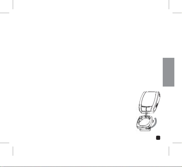
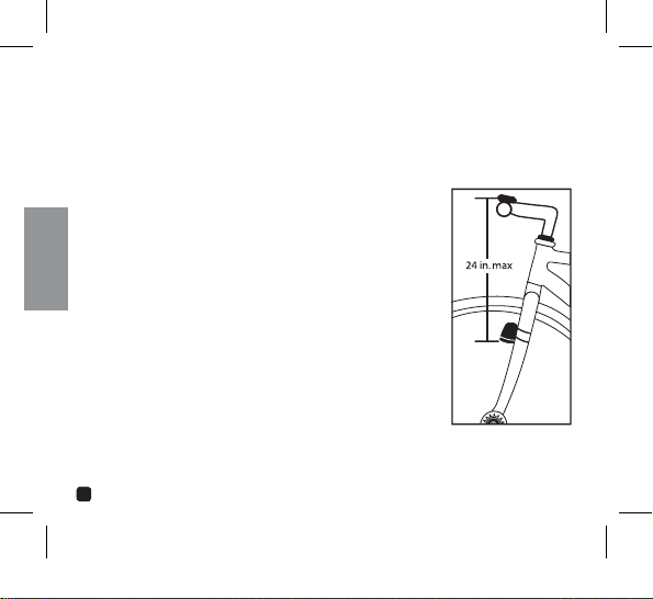
s #!54)/. Mount the Cyclecomputer according to the directions in this instruction
manual.
s #!54)/. Avoid direct impact to the Cyclecomputer unit.
s #!54)/. Do not submerge the Cyclecomputer unit.
s #!54)/.Avoid using the Cyclecomputer unit in or near strong electromagnetic fields
such as high-voltage power lines or other transmitters.
s #!54)/. Do not disassemble the unit.
s #!54)/.Make sure the magnet and the transmitter are well aligned and check them
regularly.
s #!54)/.PRO Scio Cyclecomputers are intended for use on bicycles only and should
not be used on any motorized vehicle.
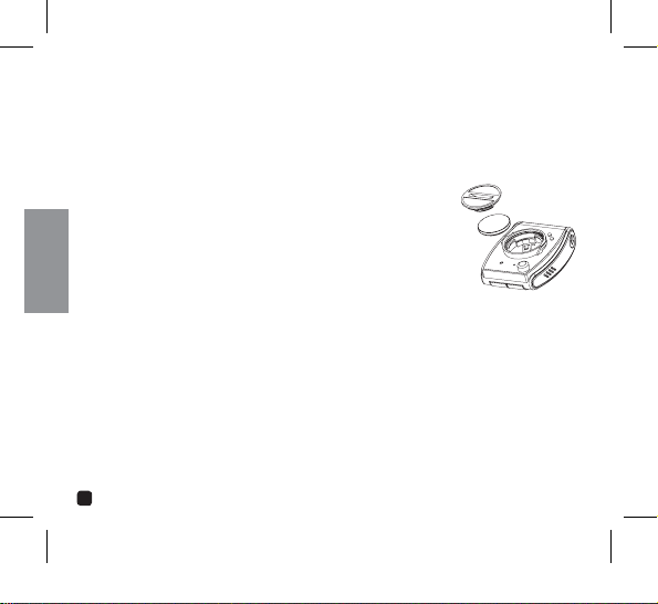
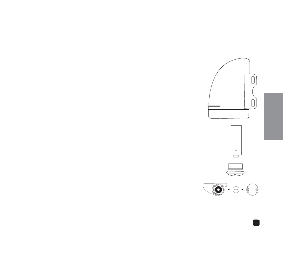
s #!54)/. Change the battery prior to failure to avoid data loss.
s #!54)/. Clean the unit with a mild detergent and a soft dry cloth. Never use any
kind of solvent or alcohol.
1
2_15.indd 4 10/11/07 6:47:48 PM

5
english
COMPONENTS OF THE CYCLECOMPUTER
#9#,/#/-054%25.)4
7)2%,%33&/2+42!.3-)44%2
(SCIO W-2.1 ONLY)
7(%%,-!'.%4
:)04)%3
7)2%,%33&/2+42!.3-)44%2
-/5.4).'0!$
(SCIO W-2.1 ONLY)
7)2%,%33-/5.4).'
"2!#+%4
(SCIO W-2.1 ONLY)
-/5.4).'"2!#+%425""%2
0!$
7)2%$42!.3-)44%2
-/5.4).'"2!#+%4
(SCIO X-1.6 ONLY)
1
2
3
4
7
6
5
8
Jet12_15.indd 5 10/11/07 6:47:49 P

6
english
REPLACING THE BATTERY
PRO Scio Cyclecomputers are powered by a CR2032 3v Lithium Battery. Under normal condi-
tions, this battery should last approximately one year.
REPLACING THE COMPUTER BATTERY
Using a coin, turn the battery door counter clockwise until the
door comes free.
2. Take care not to damage the O-ring seal for the battery com-
partment and carefully remove the old battery.
3. Place a new battery in the battery compartment with the posi-
tive (+) side toward the battery door. Be extremely careful not
to bend the battery contact when inserting a new battery.
4. Place the battery door over the opening and tighten it down by using a coin and turn-
ing in a clockwise direction.
5. If the O-ring has been damaged, replace it before reinstalling the battery door.
#!54)/.Extreme care should be taken when replacing the battery to ensure the unit
remains fully water resistant. Failure to properly replace the battery and correctly seal the
unit may cause the unit to become damaged and may void the warranty.
1
2_15.indd 6 10/11/07 6:47:51 PM

7
english
CHANGING THE BATTERY IN THE WIRELESS
SPEED TRANSMITTER
The Wireless Speed Transmitter uses a 23A 12v Alkaline battery.
Under normal conditions, this battery should last approximately
one year.
1. Using a coin, turn the battery door counter clockwise until the
door comes free.
2. Take care not to damage the O-ring seal for the battery
compartment and carefully remove the old battery.
3. Place a new battery in the transmitter positive (+) side toward
the battery door.
4. Place the battery door over the opening and tighten it down
by using a coin and turning in a clockwise direction.
5. If the O-ring has been damaged, replace it before reinstalling
the battery door.
./4%Extreme care should be taken when replacing the battery to
ensure the unit remains fully water resistant. Failure to properly
replace the battery and correctly seal the unit may cause the unit to
become damaged and may void the warranty.
Jet12_15.indd 7 10/11/07 6:47:51 P

8
english
INSTALLING THE WIRED CYCLECOMPUTER ON YOUR
BIKE - PRO SCIO X-1.6
INSTALLING WIRED FRONT WHEEL SPEED SENSOR
AND BRACKET
The PRO Scio X-1.6 uses a single wired sensor attached to the front fork.
1. Attach the front wheel sensor to either fork blade using the zip-ties
provided. Snug up the zip-ties but do not fully tighten them.
2. Attach the spoke magnet to a spoke on the same side of the wheel
as the sensor. Tighten the attachment screw just enough to hold the
magnet in place but loose enough so that it is still movable.
3. Adjust the position of the sensor and magnet so they are in proper
alignment as shown in the drawing and tighten the zip-ties and
magnet.
./4% The magnet should pass 1-3mm away from the sensor. The closer
you can get the magnet to the sensor the better.
1
2_15.indd 8 10/11/07 6:47:52 PM

9
english
INSTALLING THE WIRED CYCLECOMPUTER ON YOUR
BIKE - PRO SCIO X-1.6
INSTALLING WIRED FRONT WHEEL SPEED SENSOR AND BRACKET
(continued)
4. Route the remaining wire and bracket up the fork securing it with tape. Excess wire
should be wrapped around the brake cable housing until there is just enough slack
remaining to allow the bracket to be attached to the handlebars. Attach the bracket
to the handlebars and tighten the zip-ties.
#!54)/.When installing the system on a bicycle with front suspension, be sure to leave
enough slack for the action of the fork.
MOUNTING THE HANDLEBAR/STEM BRACKET
Place the Cyclecomputer unit into the mounting bracket and turn clockwise until the
unit snaps into place.
./4%When mounting the unit on the stem, you must first remove the
4 screws on the back of the mounting bracket and rotate it 90 degees.
Replace the screws - do not overtighten. The unit is now properly aligned
for mounting on the stem.
2. Place the mounting brakcet in the desired position on handle bars or
stem.
3. Thread the zip-ties provided through the holes on one side of the
mounting sleeve and around the handlebar or stem. Once the unit is
positioned correctly, secure the zip-ties and trim off the excess ends.
Jet12_15.indd 9 10/11/07 6:47:54 P

10
english
INSTALLING THE WIRELESS CYCLECOMPUTER ON
YOUR BIKE - PRO SCIO W-2.1
INSTALLING THE WIRELESS FORK TRANSMITTER
The PRO Scio W-2.1 receives speed and distance from a wireless transmitter mounted to
the front fork.
1. Attach the wireless front wheel sensor and rubber mounting
pad to the front of the left fork blade using the zip-ties
provided so the battery cap is pointing downward. Snug up
the zip-ties but do not fully tighten them. The sensor should
be mounted as high on the fork blade as possible. The range
of the transmitter is approximately 18in (46cm). Mounting
it high on the fork will assure good signal reception. Other
mounting locations may work, but we feel this is the best
location for most applications.
2. Attach the spoke magnet to a spoke on the same side of
the wheel as the sensor. Tighten the attachment screw just
enough to hold the magnet in place but loose enough so that
it is still movable.
1
2_15.indd 10 10/11/07 6:47:54 PM

11
english
INSTALLING THE WIRELESS CYCLECOMPUTER ON
YOUR BIKE - PRO SCIO W-2.1
INSTALLING THE WIRELESS FORK TRANSMITTER
(CONTINUED)
3. Adjust the position of the sensor and magnet so they are in
proper alignment as shown. The magnet should pass by the
sensor adjacent to the molded plastic line at a distance of
1-3mm.
4. Once everything is in alignment, fully tighten the spoke
magnet in place and tighten the zip-ties holding the sensor to
the fork.
continued next page
Jet12_15.indd 11 10/11/07 6:47:55 P

12
english
INSTALLING THE WIRELESS CYCLECOMPUTER ON
YOUR BIKE
MOUNTING THE HANDLEBAR/STEM BRACKET
Place the Cyclecomputer unit into the mounting bracket and turn
clockwise until the unit snaps into place.
./4%When mounting the unit on the stem, you must first remove the
4 screws on the back of the mounting bracket and rotate it 90 degees.
Replace the screws - do not overtighten. The unit is now properly aligned
for mounting on the stem.
2. Place the mounting bracet in the desired position on handle bars or
stem.
3. Thread the zip-ties provided through the holes on one side of the
mounting sleeve and around the handlebar or stem. Once the unit
is positioned correctly, secure the zip-ties and trim off the excess
ends.
1
2_15.indd 12 10/11/07 6:47:57 PM

13
english
KEYS & THEIR FUNCTIONS
MODE KEY
s !DVANCESTHROUGHMAINOPERATING
modes
s 0RESS(OLD3ELECTS")+%OR")+%
in Average Speed mode
s 3ETSVARIABLEBEINGADJUSTEDINTHE
Programming Sequence
s $EACTIVATES3#!.MODE
SET KEY
s !DJUSTSVARIABLEBEINGSETINTHE
Programming Sequence
s 3ELECTS$ISTANCE50OR$/7.IN
Distance Mode
s 0RESS(OLD!CTIVES3#!.MODE
during operation
s $EACTIVATES3#!.MODE
s 3TOPS3TARTS3TOPWATCH
Jet12_15.indd 13 10/11/07 6:47:58 P

14
english
MAIN OPERATING MODES
The PRO Scio X-1.6 and PRO Scio X-2.1 have 7 main operating modes. Scroll through modes
by 0RESSING the -ODE key.
4)-%/&$!9 2)$%4)-% $)34!.#% /$/-%4%2
!6%2!'%30%%$ -!830%%$ 34/07!4#(
1
2_15.indd 14 10/11/07 6:48:02 PM

15
english
MAIN OPERATING MODES
SCAN MODE
The PRO Scio X-1.6 and PRO Scio X-2.1 can be programmed to automatically scan though all
operating modes in 2-second intervals. To activate Scan mode, 0RESS(OLD the 3ET key for
2 seconds in any operating mode. To deactivate Scan mode, 0RESS the 3ETOR-ODE key.
Jet12_15.indd 15 10/11/07 6:48:06 P

16
english
MEASURING WHEEL SIZE
DETERMINING YOUR WHEEL SIZE
PRO Scio Computers use the rolling circumference of your wheel and tire combination to
determine speed and distance. The more accurate this setting, the more accurate your ride
INFORMATIONWILLBE(OWEVERVARIATIONSOFLESSTHANMMFROMTHEACTUALCIRCUMFERENCE
will have very little impact on the overall accuracy of the unit.
)FYOURWHEELTIRESIZEISNOTONEOFTHESIZESINTHEACCOMPANYINGCHARTORIFYOUDESIRE
absolute accuracy, you may enter an exact wheel circumference into the system. Use the
METHODONTHEFOLLOWINGPAGEFORMEASURINGTHECIRCUMFERENCEOFYOURWHEELTIRECOMBINA-
tion.
WHEEL SIZE CIRCUMFERENCE
26 X 1.0 1973
26 X 1.5 2026
26 X 1.6 2051
26 X 2 2114
700 X 20C 2114
700 X 23C 2133
WHEEL SIZE CIRCUMFERENCE
700 X 25C 2146
700 X 28C 2149
700 X 32C 2174
700 X 35C 2205
700 X 40C 2224
1
2_15.indd 16 10/11/07 6:48:06 PM

17
english
MEASURING WHEEL SIZE
MEASURING WHEEL SIZE USING ROLLOUT METHOD
The roll-out method is the most accurate method for determining the circumference of your
WHEELTIRECOMBINATION
1. On a flat open surface make a mark on your tire and the floor exactly where they
meet.
2. Roll your bike forward one full revolution of the front wheel and mark the point on the
floor where the revolution is complete. For maximum accuracy be sitting on the bike
while someone rolls you and the bike forward.
3. Measure the distance from the first mark to the second in millimeters and enter the
resulting number into your computer.
Jet12_15.indd 17 10/11/07 6:48:07 P

18
english
SELECTING MILES OR KILOMETERS, SETTING WHEEL SIZE AND
ODMETER
The main Programming Sequence calibrates the computers measurments for both Bikes 1
and 2. In order to assure accuracy of the unit, all fields of information must be programmed.
1. )N/DOMETER-ODE0RESS(OLDTHE-ODEKEYTOENTERTHE3ETTING3EQUENCE
.OTEYOUMUSTENTERALLlELDSOFINFORMATIONTORETURNTO/PERATINGMODE
SELECTING MILES OR KILOMETERS
2. 3ELECT-ILESOR+ILOMETERSBY0RESSINGTHE3ETKEY
3. 3ET-ILESOR+ILOMETERSBY0RESSINGTHE-ODEKEY4HECOMPUTERWILLAUTOMATICALLY
advance to set Wheel Size.
PROGRAMMING THE CYCLECOMPUTER
ADJUST:
PRESS SET SET:
PRESS MODE
SET & ADVANCE
TO SET
WHEEL SIZE:
PRESS MODE
1
2_15.indd 18 10/11/07 6:48:08 PM

19
english
SETTING WHEEL SIZE
4. Adjust wheel circumference of Bike 1 starting with right through left digits (digit
being adjust will blink).
5. Adjust blinking digit by pressing the Set key.
6. Set digit and advance to next by Pressing the Mode key.
7. Once all fields have been adjusted, Press the Mode key to advance to adjust wheel
circumference for Bike 2. Repeat Steps 4 through 6.
8. Once Bike 2 wheel circumference has been set, press the mode key to advance to set
Odometer.
PROGRAMMING THE CYCLECOMPUTER
ADJUST:
PRESS SET SET & ADVANCE:
PRESS MODE ADJUST:
PRESS SET
CONTINUE
THROUGH ALL
FIELDS
SET WHEEL SIZE &
ADVANCE TO SET
ODOMETER:
PRESS MODE
Jet12_15.indd 19 10/11/07 6:48:09 P

20
english
SETTING ODOMETER
PRO Scio Cyclecomputers allow you to manually program your odometer. This is useful
for preserving distance totals in the event of battery failure or if you need to reset the
computer for any reason.
9. Set Odometer of Bike 1 starting with right through left digits (digit being adjust will
blink).
Adjust blinking digit by pressing the Set key.
Set digit and advance to next by Pressing the Mode key.
Once all fields have been adjusted, Press the Mode key to advance to Odometer for
Bike 2. Repeat Steps 9 through 11.
13. Once Bike 2 Odometer has been set, Press the Mode key to return to Operating mode.
PROGRAMMING THE CYCLECOMPUTER
ADJUST:
PRESS SET SET & ADVANCE:
PRESS MODE ADJUST:
PRESS SET
CONTINUE
THROUGH ALL
FIELDS
SET ODOMETER
& RETURN TO
OPERATING MODE:
PRESS MODE
1
2_15.indd 20 10/11/07 6:48:10 PM
This manual suits for next models
1
Table of contents
Other Pro Bicycle Accessories manuals