manuals.online logo
Brands
  1. Home
  2. •
  3. Brands
  4. •
  5. Retrospec
  6. •
  7. Bicycle
  8. •
  9. Retrospec Harper Fixie User manual

Retrospec Harper Fixie User manual

ASSEMBLY INSTRUCTIONS
HARPER FIXIE
TOOLS 1
UNPACK YOUR BIKE
SADDLE
HANDLEBARS
WARNING
Using the bike with the minimum insertion line on the lower
portion of the seat post showing above the frame could result
in a failure of the seat post and/or the frame causing a loss of
control with potential injury to rider. Such failures are not
covered by warranty as it is improper use of the product.
WARNING Using the bike with the minimum insertion line on the lower portion of the seat post showing above the
frame could result in a failure of the seat post and/or the frame causing a loss of control with potential
injury to rider. Such failures are not covered by warranty as it is improper use of the product.
WARNING Installing the stem with the minimum insertion mark showing outside of the frame could create a
dangerous condition allowing the stem to break causing the rider to lose control resulting in serious
injuries to the rider (Figure 7).
What we give you: 3 Hex Wrenches (4mm, 5mm, & 6mm), a 10-function multi-tool.
What you need: Scissors, Phillips Screwdriver, 15mm wrench or crescent wrench.
Cut the shipping straps on the outside of the box.
Remove the box staples as these are sharp and can cut you as you access the bike. Lift bike out by frame and rear wheel.
Rotate the fork so that it is facing forward of the bike (Figure 1). Place the bike on the ground, so it’s standing upright on the fork dropouts and rear tire.
Cut all of the packing zip ties.
Separate the front wheel from the bike by carefully slipping it away from the crank arm, which is resting within the spokes.
Remove the accessory box and set it aside.
Ex-mine your new bike for any visible damage that may have occurred during shipping.
Special Note: For tightening all fasteners, please refer to Appendix D in the back of your owner’s manual for all fastener torque specifications.
1-
2-
3-
4-
5-
6-
7-
8 -
1-
2-
3-
4-
5-
1-
2-
3-
4-
.
Remove the plastic shipping plug from the top of the seat tube (Figure 2).
Use the included Hex wrench to loosen the seat clamp at the top of the seat tube.
RECOMMENDED; Apply a thin layer of grease to the inside of the frame seat tube.
Insert the seat with the seat post into the seat tube of the frame to at least the minimum insertion line on the shaft
of the seat post. WARNING! The minimum insertion line must NOT show above the seat tube (Figure 3).
Using the Hex wrench, tighten the seat clamp once it is at the correct height.
Note: You can make the final adjustment to the height of the seat as needed after the bike is assembled.
Loosen the stem bolt at the top of the stem one turn and remove the plastic packing cap from the bottom of the
stem (Figure 4). RECOMMENDED; apply a thin layer of grease to the end of the stem shaft by the wedge.
Untwist the handlebars and control cables and insert the quill end of the stem into the fork steer tube. You may
have to loosen the bolt and wedge a small amount to allow the quill to fit into the steer tube (Figure 5).
Make sure that the fork is facing forward and the handlebars are lined up with the fork dropouts.
Adjust the height of the stem to your desired level and tighten the stem bolt using a 6mm wrench. You can make
final adjustments to the height of the stem after the bike is assembled (Figure 6). NOTE: Be sure that the minimum
insertion mark on the shaft of the stem is inside the frame, it must not be visible outside of the frame (Figure 7).
FRONT
23
4 5
67
MIN INSERT
25.4
MAX
HT
22.2
MAX
HT
22.2
PLASTIC
SHIPPING
PLUG
PLASTIC
PACKING
CAP
APPLY GREASE
STEM QUILL
INTO FORK
STEER TUBE
STEM ADJUST
HANDLEBAR
ADJUST
MIN INSERT
25.4
1-
2-
3-
4-
5-
1-
2-
3-
4-
5-
6-
FRONT WHEEL
PEDALS
8
Flip the bike over so it’s resting on the saddle and handlebars.
Remove the small black plastic protector from the fork dropouts.
Loosen the axle nuts on the front wheel and insert the front wheel into the fork dropouts. Insert the tab of the safety washers into the small holes on the outside of the fork dropouts (Figure 8).
Inspect the wheel to make sure it is centered in the fork (Figure 9). Tighten each axle nut a little at a time with a 15mm wrench, alternating between sides, until each axle nut is properly tightened.
Return the bike onto its wheels and align the handlebar stem to the front wheel. Once the stem is aligned to the front wheel, tighten the stem bolt located at the top of the stem (Figure 6).
Right Pedal
Locate the pedal stamped “R” on the end of the spindle (this is the RIGHT pedal) (Figure 10).
RECOMMENDED; Apply a thin layer of grease to the pedal threads prior to installation.
Carefully insert the Right pedal into the Right side crank arm (the side with the chain) and thread it Clockwise (Figure 11). You should be able to thread the pedal in part of the way by hand with minor
resistance. If it seems dicult and binds, stop, remove the pedal, realign the threads and try again. Be sure you are turning the right pedal axle in a clockwise direction!
Tighten the pedal with a 15mm or adjustable wrench until the pedal is securely attached to the crank arm. The pedals need to be tightened with a considerable amount of force so that they do not come
lose.
Left Pedal
Locate the pedal stamped “L” on the end of the spindle (this is the LEFT pedal) (Figure 10).
RECOMMENDED; apply a thin layer of grease to the pedal threads and insert your Left pedal into the Left side crank arm.
Thread it Counterclockwise and tighten with a 15mm or adjustable wrench following the instructions in step #3 above (Figure 12).
NOTE: Be sure to tighten both pedals with an adjustable wrench or 15mm open end wrench to the recommended torque specification
otherwise they will unscrew while riding causing an unsafe condition for the rider and damaging the threads in the crank.
10
11 12
9
SAFETY
WASHER
FORK DROPOUT SMALL
HOLE
.
1-
2 -
3-
4-
1-
2 -
3-
1-
2 -
3-
4-
5-
6-
7-
8-
13 14
17
BRAKES
REFLECTORS
BEFORE YOUR FIRST RIDE
SERIAL NUMBER
TIRES
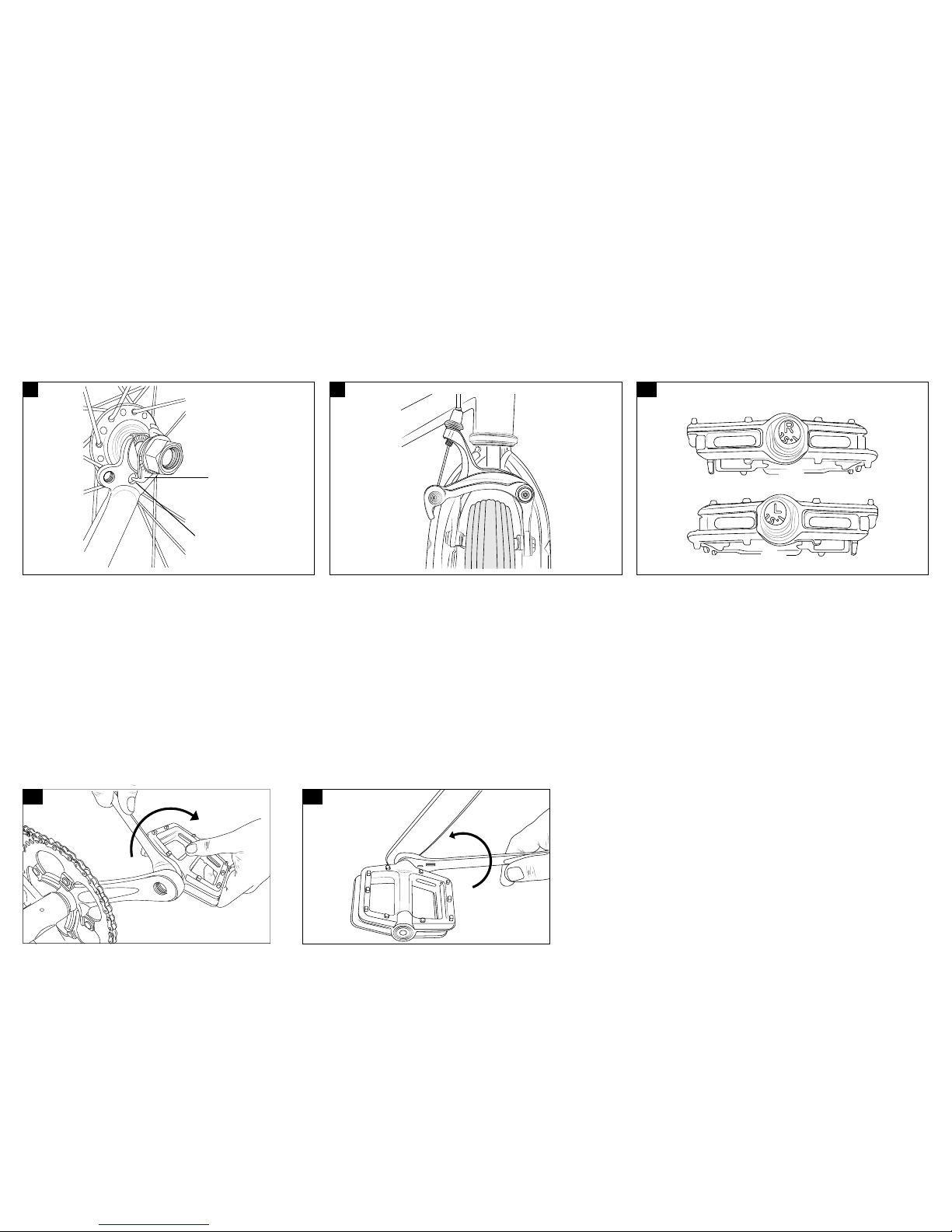
FLIP - FLOP REAR HUB - To switch between the fixed cog and the freewheel cog
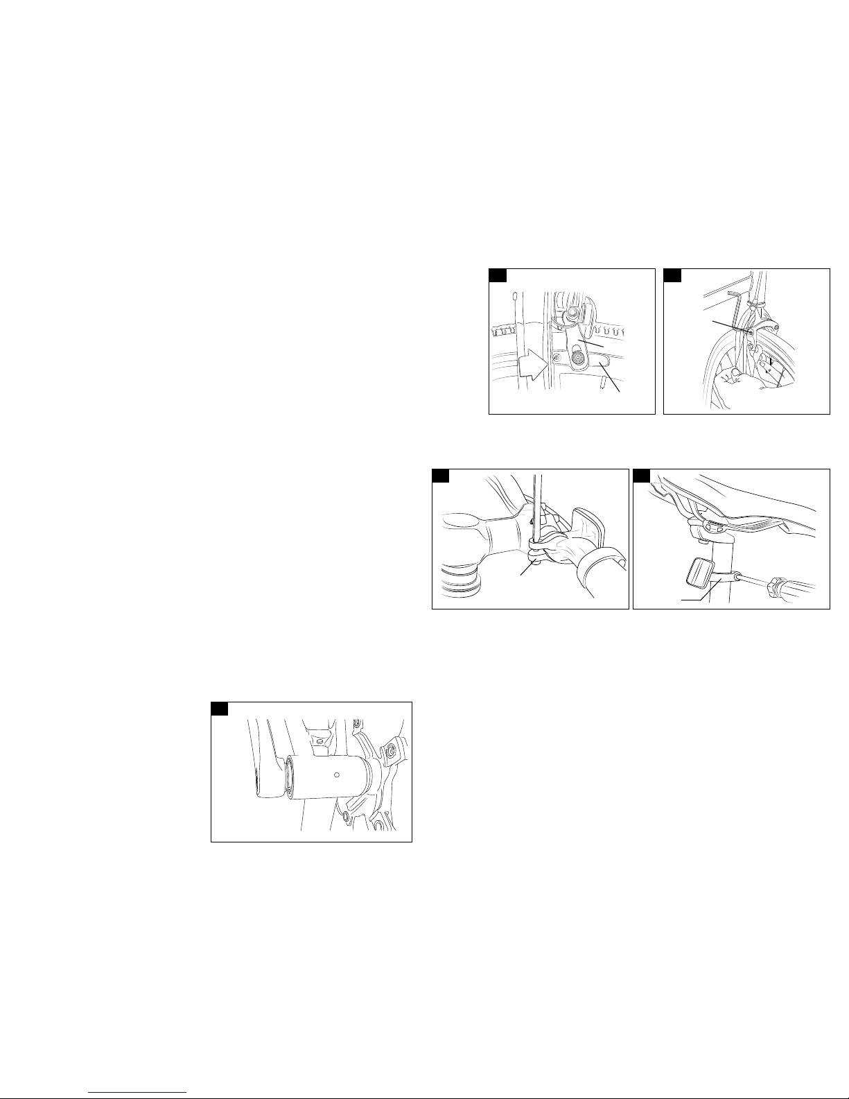
Be sure that the brake pads are aligned with the curve of the rim and that they contact the rim surface flat and
evenly (Figure 13). The brake shoe angle and height can be adjusted by loosening the Hex bolt attaching the
brake shoe to the brake arm. Notice that the brake shoe can articulate a certain amount up and down and side to
side.
Loosen the brake cable anchor at the brake arm held by an Hex bolt allowing the brake cable to freely glide
through its anchor (Figure 14).
Squeeze the brake arms together until the brake shoes contact the rim surface. Be sure that the black release
lever at the brake arm anchor is in the down position. Pull the cable taught through its anchor and tighten the
cable anchor bolt (Figure 14).
Squeeze the brake lever hard several times to take the stretch out of the cable and make sure that it does not slip
through its anchor. If the cable tension is too tight to allow the wheel to spin freely, loosen the anchor bolt and
give the cable some slack. If the cable has too much slack and you cannot apply enough stopping force to the
rim, repeat procedure #3 to take the slack out of the cable.
Be sure that the brake arms are evenly spaced from the wheel and there is some clearance between the brake pads and the rim surface. If the brake pads are not evenly spaced from the wheel, you can
balance the spacing by gripping the brake assembly and rotating until it is centered with the wheel.
NOTE: We highly recommend taking your bike to a local bike shop and having your brakes set-up by a professional mechanic
Attach the plastic brackets to the handlebar and seat post. (Figure 15 - Front).
Slide the reflectors onto the brackets (white in the front, red in the back). (Figure 16 - Rear).
Attach the wheel reflectors onto the spokes of the wheels (If not already installed at the factory).
We strongly recommend you take your bike to
a professional bike shop and have them check
your work and fine tune the bike to ensure
your bike is safe to ride.
It is important that you locate and
record the serial number of your
bicycle in case of a recall or if the
bicycle is stolen. The serial number
can be found under the crank bottom
bracket stamped into the frame
(Figure 17).
Loosen the nut on the rear wheel chain tensioner until it is loose enough to swing out of the way of
the frame dropout.
Loosen the axle nuts.
Push the wheel towards the front of the bike to loosen the chain and slip the chain o of the cog.
Remove the rear wheel, remove the axle nuts and washers, switch the chain tensioner to the oppo-
site side of the axle and replace the axle washers and nuts.
Flip the wheel around and place it back into the frame.
Replace the chain on the cog.
Pull the wheel back so the chain is taut and tighten the nut on the end of the chain tensioner to
adjust chain tension. Do not over tighten the chain. There should be approximately ¼” of chain
slack up and down when properly adjusted.
While holding the wheel centered in the frame, tighten the axle nuts a little at a time alternating
between each one until the axle nuts are tight holding the rear wheel securely in the frame.
* Locate the tire manufacturer’s recommended inflation pressure found on the tire sidewall (listed
as “PSI”).
* Using a hand or floor pump with a gauge, begin to inflate the tire to half its recommended infla-
tion pressure and check to see that the tire is properly seated on the rim. Be sure to inspect both
sides of the tire for proper fit.
* If the tire is seated unevenly or bulges out along the rim, let some air out of the tire and reposi-
tion the tire by hand so that it sits evenly on the rim.
* Continue to inflate the tire to the manufacturer’s recommended pressure.
* Do not exceed the recommended pressure as this will cause an unsafe condition potentially
causing the tire to unexpectedly explode.
* Do not use a compressed air device to inflate your tires as the rapid inflation of the tire can
cause it to blow o the rim.
* Tires and tubes are not warranted against damage caused by over-inflation or punctures from
road hazards.
15 16
F
J
1
2
3
4
5
6
7
8
9
1
2
3
BRAKE ARM
CABLE
ANCHOR
BOLT
BRAKE SHOE
FRONT
REFLECTOR
BRACKET
REAR
REFLECTOR
BRACKET

Other Retrospec Bicycle manuals

Retrospec AMOK User manual

Retrospec

Retrospec AMOK User manual

Retrospec JUDD User manual

Retrospec

Retrospec JUDD User manual

Retrospec SULLY User manual

Retrospec

Retrospec SULLY User manual

Retrospec KODA 12 User manual

Retrospec

Retrospec KODA 12 User manual

Retrospec CUB User manual

Retrospec

Retrospec CUB User manual

Retrospec Jax User manual

Retrospec

Retrospec Jax User manual

Retrospec BEAUMONT User manual

Retrospec

Retrospec BEAUMONT User manual

Retrospec BEAUMONT MINI User manual

Retrospec

Retrospec BEAUMONT MINI User manual

Popular Bicycle manuals by other brands

Lacros TROTTER T400XL Original manual

Lacros

Lacros TROTTER T400XL Original manual

Gazelle Innergy Series user manual

Gazelle

Gazelle Innergy Series user manual

Stevens MTB user manual

Stevens

Stevens MTB user manual

Canyon GRAIL:ON quick start guide

Canyon

Canyon GRAIL:ON quick start guide

BESV CF1 Quick assembly guide

BESV

BESV CF1 Quick assembly guide

AZUB Recumbents user guide

AZUB

AZUB Recumbents user guide

ARGENTO PERFORMANCE user manual

ARGENTO

ARGENTO PERFORMANCE user manual

Vuly Balance Bike manual

Vuly

Vuly Balance Bike manual

MBM KAIROS SUB user manual

MBM

MBM KAIROS SUB user manual

Sun Bicycles shortcut Supplemental owner's manual

Sun Bicycles

Sun Bicycles shortcut Supplemental owner's manual

Magnum Ui5 user guide

Magnum

Magnum Ui5 user guide

Urban Arrow Shorty user manual

Urban Arrow

Urban Arrow Shorty user manual

ARGENTO BiMax XL user manual

ARGENTO

ARGENTO BiMax XL user manual

Larry vs Harry eBullitt E6100 manual

Larry vs Harry

Larry vs Harry eBullitt E6100 manual

KENT Li'l Farmer 81692 Assembly manual

KENT

KENT Li'l Farmer 81692 Assembly manual

IKEA Sladda manual

IKEA

IKEA Sladda manual

KNAAP BIKES AMS user manual

KNAAP BIKES

KNAAP BIKES AMS user manual

Milazo Adult Bicycles instruction manual

Milazo

Milazo Adult Bicycles instruction manual

manuals.online logo
manuals.online logoBrands
  • About & Mission
  • Contact us
  • Privacy Policy
  • Terms and Conditions

Copyright 2025 Manuals.Online. All Rights Reserved.