Anatomic SITT Zitzi Flipper Pro Flex User manual

Gas piston
Electric
EN
User Manual
Zitzi Flipper Pro Flex
2017-09-05

2
User manual Zitzi Flipper Pro Flex www.anatomicsitt.com | +46 11 16 18 00
Safety precautions ................................. 3
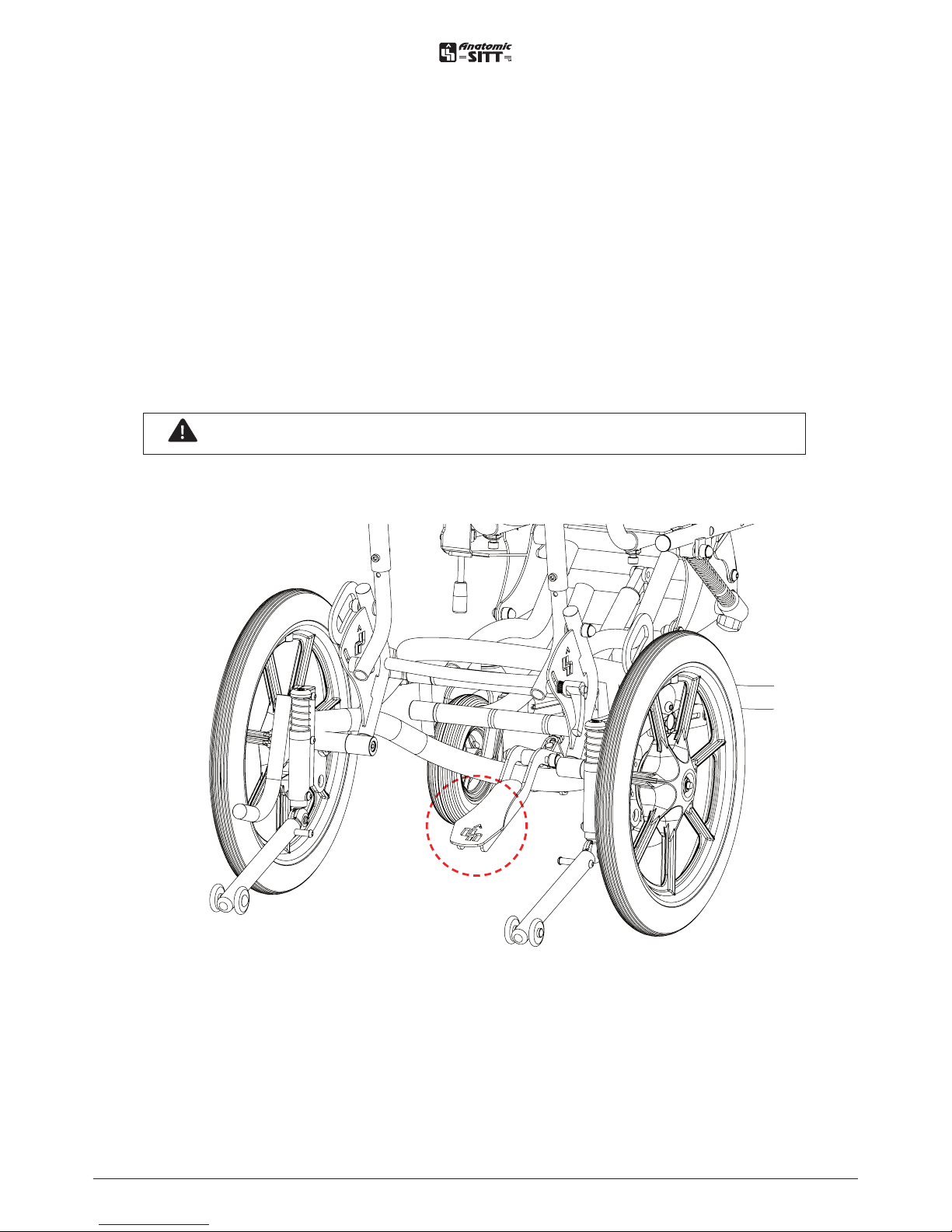
Adjustable seat height - Gas piston ...4
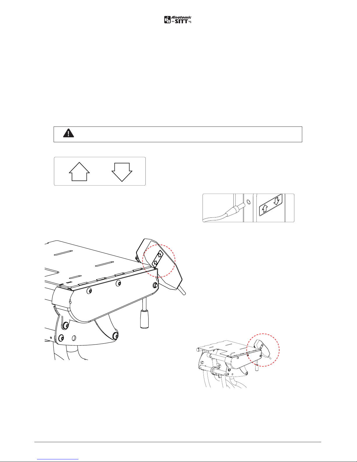
Adjustable seat height - Electric......... 5
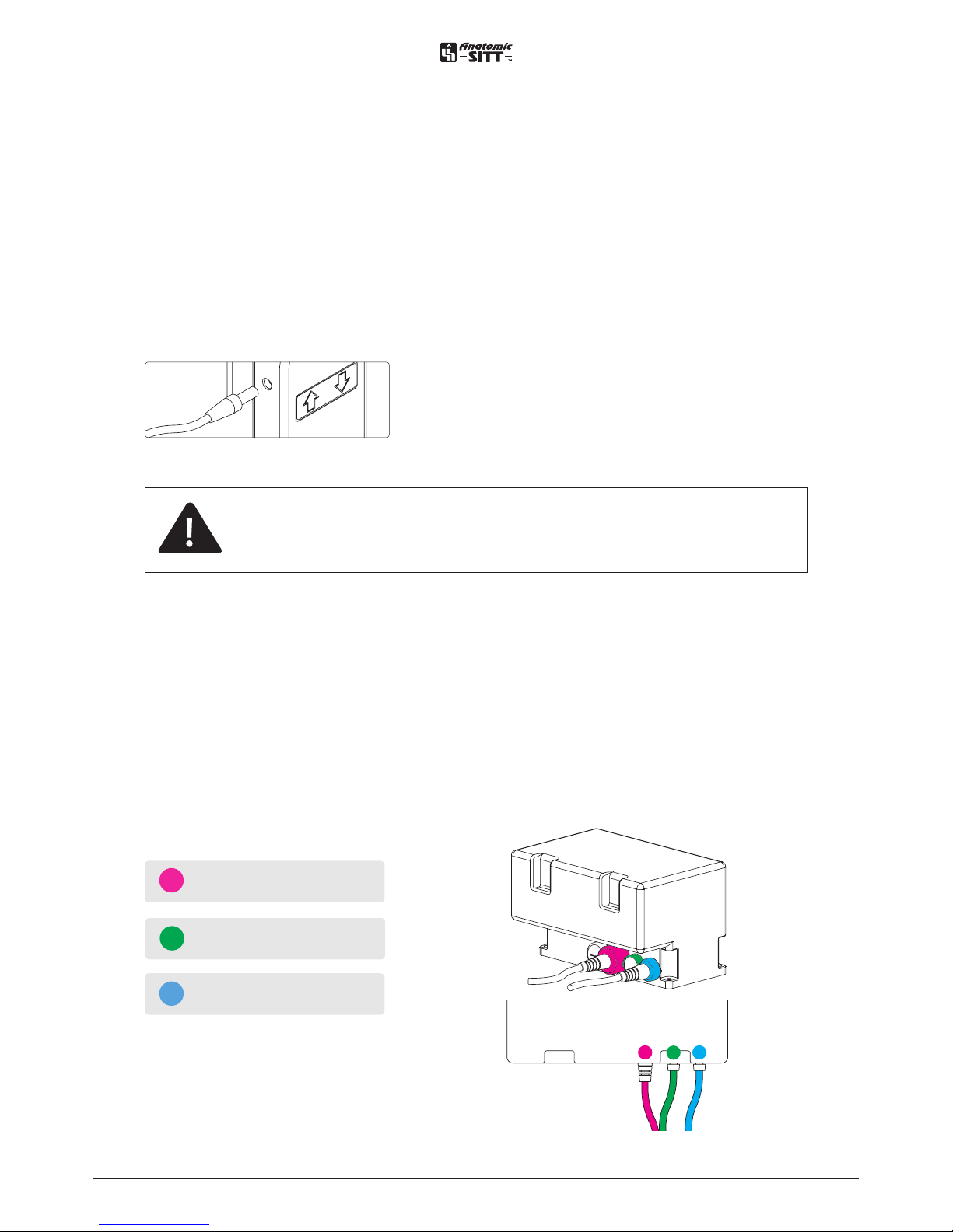
Charging the battery..............................6
Connecting the electronic box ............6
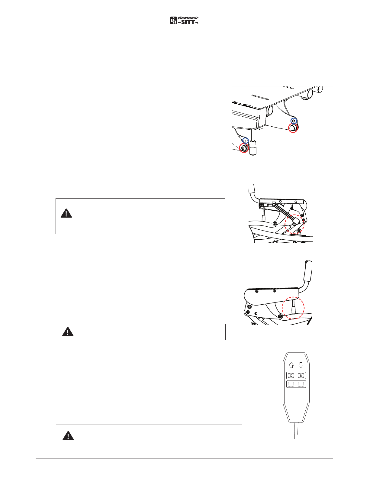
Tilt function.............................................. 7
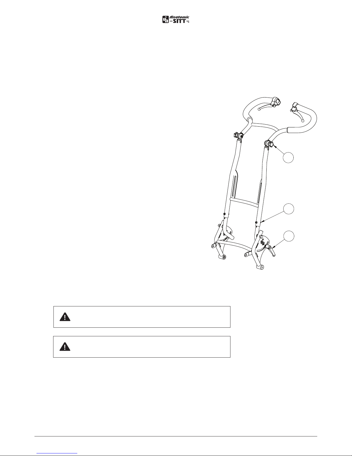
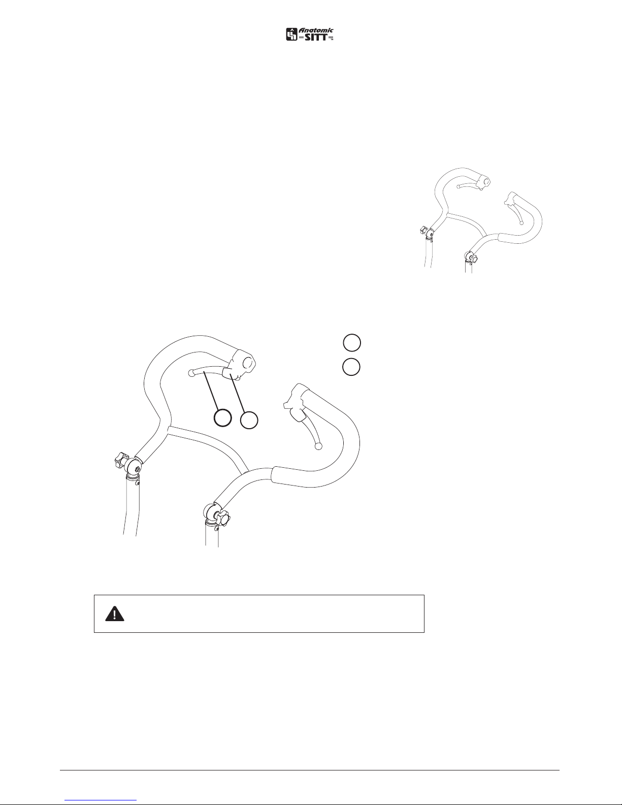
Driving bow.............................................. 8
Parking brake...........................................9
Mounting of rear wheels ..................... 10
Mounting of anti-tippers & step bar.. 11
Transportation kit ..................................12
Transportation in vehicles ...................13
Footrest................................................... 14
Calf support ............................................15
Footrest high edge, single stay......... 16
From single stay to double stay............. 17
Drilling instr. whole footrest plate ......... 18
Drilling instr. divided footrest plate ...... 19
Mounting of a seat system ................... 20
Maintenance instructions.....................21
Reconditioning .......................................21
Spare parts ..............................................21
Comb. & suitable seating system......22
Markning .................................................22
Disassembly & Dismantlement ..........22
Warranty .................................................22
Technical data........................................23
Table of contents

3
User manual Zitzi Flipper Pro Flex www.anatomicsitt.com | +46 11 16 18 00
Safety precautions
Introduction
In order to use the Zitzi Flipper Pro Flex in its full extent, it is important that you
read this manual. This applies to everyone close to the user.
The product is intended for users with seating problems and fits many dierent
kinds of diagnoses. Adaptation/fitting of Zitzi Flipper Pro Flex must be done by a
medically qualified person.
If you need additional information, please contact Anatomic SITT AB.
Field of application
The product is only intended for use as a seating system together with chassis
produced by Anatomic SITT AB.
If other uses are desired, please contact Anatomic SITT AB.
Correspondence
Zitzi Flipper Pro Flex and its accessories are CE marked products. A unique serial
number is located on a label placed under the activation housing. This serial num-
ber should be quoted in any correspondence regarding the product.
Crash tested
Zitzi Flipper Pro Flex is crash tested and approved in vehicle according to
7176-19 for 75 kg.
Check the checkbox if the product
is CUSTOMIZED.
The CE Mark is no longer valid and
should be removed.
Place of label
This product is manufactured by Anatomic SITT AB
Postal address Anatomic SITT AB, Box 6137, SE-600 06 Norrköping
Street address Anatomic SITT AB, Terminalgatan 1, SE-603 61 Norrköping
Phone +46 11-161800
Fax +46 11-162005
Email info@anatomicsitt.com
Webb anatomicsitt.com
Instructions movies youtube.com/anatomicsitt
Follow us on facebook.com/anatomicsitt

4
User manual Zitzi Flipper Pro Flex www.anatomicsitt.com | +46 11 16 18 00
Adjustable seat height - Gas piston
The seat height are adjustable from 29-65 cm.
It can easily be adjusted with the handle grip.
Keep in mind that you always should have a hand on the seating system when you
are adjusting it.
• Release the locked position by pressing the handle grip.
• Adjust the seat height to desired position.
• Let go of the handle grip when you achieved the desired height.
The height is now locked
Note! Be careful to avoid risk of pinching

5
User manual Zitzi Flipper Pro Flex www.anatomicsitt.com | +46 11 16 18 00
• Contact for charging
Adjustable seat height - Electric
The seat height are adjustable from 29-65 cm.
It can easily be adjusted with the electric hand control.
Keep in mind that you always should have a hand on the seating system when you
are adjusting it.
• Up arrow raises the seat plate
• Down arrow lowers the seat plate
Note! Be careful to avoid risk of pinching

6
User manual Zitzi Flipper Pro Flex www.anatomicsitt.com | +46 11 16 18 00
Charging the battery
Connect the cable of the charger into a regular wall socket (220 V).
Then connect the cable of the charger into the side of the hand control.
You have to charge the battery for at least 24 hours the first time you use it.
It is very important that you never let the battery uncharge completely. If so, it may
be damage..
Charge the battery for 24 hours the first time.
Thereafter, charge it every night.
Never let the battery uncharge completely.
ACTUATOR (LIFT)
HAND CONTROL
Connecting the electronic box
When connecting the electronic box the actuator for the lift should be connected to
the box input marked 1.
At the option of electronic tilt function, the electronic box and the electronic
controller have to be replaced for this intended. The actuator for the tiltfunction then
should be connected to the box input marked 2.
12
ACTUATOR (TILT) opyion
The connection for charger is
the side of the hand control.

7
User manual Zitzi Flipper Pro Flex www.anatomicsitt.com | +46 11 16 18 00
Tilt function
Flipper Pro Flex has two dierent tilt positions, which
is set using holes on the side of the seat plate. If the
piston is attached to the lower hole (see figure), tilt is
obtained at 0° -30°. If the piston is inserted into the
upper hole, a tilt of -5° to 25° is obtained.
Knob (A),
right side
Tilting with gas piston
The angle of the seat plate are adjustable 0-30° and
can be adjusted by loosen the knob (A) and pressing
the lever (B), then push the seat plate down- and
forward. Release the lever (B) to lock the desired
angle, and then tighten the knob (A) to ensure that
the angle is locked.
The spring on the side of the seat plate helps to
reset the seat plate to its original position.
Always check that the tilt is locked when you reach
the desired angle.
The knob (A) must always be locked after any
adjustment.
Spring return
Control
Locking
Note! To reset the seat angle to its starting
position, loose the knob (A), press the lever
(B) and pull the seat plate up and backwards
by griping the handle.
Electric tilting
The angle of the seat plate are adjustable 0-30° and
can be adjusted by loosen the knob (A) and pressing
button (C) for tilting forward and button (D) for
tilting backward. Release the button on the hand
control when the desired tilt position is reached.
Lock the knob (A) to ensure that tilt position is
locked.
Lever (B),
left side
Hand
control
Montering av negativ tilt Flipper pro
Flipper pro har två olika lägen för tilt vilket ställs in med hjälp av hål vid sidan om sittplattan. Om
kolven fästs in i hålet längst ned (som på bild nedan) erhålls tilt på 0-30O. Om kolven fästs in i hålet
framför erhålls en tilt på -5-25O.
Standard tilt
Negative tilt
Tilt function
Note! It is very important that the knob (A) is
released before using the electric tilt function.
Note! Be careful to avoid risk of pinching

8
User manual Zitzi Flipper Pro Flex www.anatomicsitt.com | +46 11 16 18 00
Angle adjustments - Handle (A)
To change the angle of the driving bows handle,
loosen the knobs (A).
Tighten the knobs when the desired angle is
reached.
Angle adjustments - Driving bow (B)
To change the angle of the driving bow, loosen
the levers (B). Tighten the levers when the
desired angle is reached.
Height adjustment - Driving bow (C)
The driving dow or driving handles can be
height adjusted in three dierent heights. Be
sure to tighten the screws (C) properly after the
desired position is reached.
Driving bow
overview
A
B
C
Driving bow
Note! All knobs, levers and screws should always
be locked after adjustment..
Note! The driving dow must rest against the back
of the seat system when transporting a vehicle.

9
User manual Zitzi Flipper Pro Flex www.anatomicsitt.com | +46 11 16 18 00
Parking brake
A Brake lever
B Locking device
Locking the brake
Lock the parking brake by pushing the brake lever
and hook in the red locking device in a suitable
notch. Then release the brake handle.
B
A
Note! Always lock the parking brake when the
chassi is standing on a sloping surface.
Unlocking the brake
Release the parking brake by pushing the
brake lever to release the locking device.

10
User manual Zitzi Flipper Pro Flex www.anatomicsitt.com | +46 11 16 18 00
A For 12” wheels
B For 16” wheels
C Anti-tipper and Step bar
A
B
C
The rear wheels can be easily removed. This can be useful for
example transportation.
Releasing the rear wheels
Release the parking brake first. Press and hold the button in the
center of the wheel. Then pull the wheel out.
Attaching the rear wheels
Press and hold the button and then slide the quick release axle
in the hub. When the wheel is all the way in it is OK to release
the button.
Quick-release
Mounting of rear wheels
Note! Ensure that the the wheel is in the locked position!

11
User manual Zitzi Flipper Pro Flex www.anatomicsitt.com | +46 11 16 18 00
Mounting of anti-tippers & step bar
The anti-tipper and step bar are mounted with common
supplied screws, nuts and washers as shown.
The step bar is place in the outside and the anti-tipper on
the inside of the hole plate.
Anti-tipper - Quick guide
The anti-tipper is used for preventing the
chassis from tipping uncontrolled backwards.
The anti-tipper can easily be folded away in
order to be out of the way.
Step down the anti-tipper and turn it aside.
Make sure to rotate it until you hear a click
indicating that it is locked away. Try to step
as far in as possible on the anti-tipper. This is
because the parts will have a longer lifetime.
Opposite the anti-tipper folds out until a
click is heard.
Direction latch
To activate the castor wheel direction latch; pull
the snap lock at the castor wheel and turn 90°.
The snap lock fastens automatically to the cor-
rect position.
anti-tipper
Step bar
C
C Holes for anti-tipper
and step bar
Note! Zitzi Flipper Pro Flex should
always be equipped with anti-tip
device given its high potential for
height adjustment
Step bar - Quick guide
The Step bar is used to facilitate raising the
front wheels of the chassi, for example at
sidewalks.

12
User manual Zitzi Flipper Pro Flex www.anatomicsitt.com | +46 11 16 18 00
Transportation kit
Mounting of the support bow
Mounted with screws and knobs as shown.
Loc-tite is used on the screws (A) during
assembly.
Mounting of the transportation kit
(front and rear)
Mounted with screws, washers and
nuts as shown.
Note that the loop of the back
bracket is pointing backwards.
Adjustment of the bow - Quick guide
• Loosen the knobs on both
sides and pull out the support
bow to end position.
• Make sure the knobs hooks
on the outer edge of the
track and then lock the
knobs.
A
A
Front transportation
kit
Rear transportation
kit
Note! Support bow must always be in
lowest position and in contact with the
vehicles floor during transport.
Note! The driving bow must always
bear against the seat system’s back
when transported in vehicles.

13
User manual Zitzi Flipper Pro Flex www.anatomicsitt.com | +46 11 16 18 00
Instructions for transportation in vehicle
Flipper Pro Flex is crash tested and approved in
vehicle according to 7176-19 for 75 kg.
Attachments must be made with straps, approved
according to ISO 10542, in the intended transport
brackets.
Attach the tie-down straps in the transport
attachments according to the picture.
The push handle should always be in contact
with the back of the seating system during
transportation in a vehicle.
Transportation in vehicles
Important! Only tighten the straps, do not strain! If the straps are
strained too much, the chassis may be deformed.
Note! The crash approval applies to load weights up to 75 kg.

14
User manual Zitzi Flipper Pro Flex www.anatomicsitt.com | +46 11 16 18 00
D
C
AA
B
Footrest
E
E
Mounting of footrest bracket - A
Fit the profile to the footrest bracket
under the seat plate with the supplied
screws in the holes at the front of the
seat plate.
Adjusting the knee joint - B
Loosen the knob (B) and adjust to
desired position. Tighten when desired
positions is reached.
Angle adjustment, foot joint - C
Loosen the knob (C) and adjust to
desired position. Tighten when desired
position is reached.
Height adjustment, foot plate - D
Loosen the knob (D) and adjust to
desired position. Tighten when desired
positions is reached.
Height adjustment, foot plate - C
Loosen the screws (E) and adjust to
desired position. Tighten when desired
positions is reached.
Important! The ”teeth” have
to fit with each other. Lock the
bolt properly!

15
User manual Zitzi Flipper Pro Flex www.anatomicsitt.com | +46 11 16 18 00
Loosen the screws A to adjust to the desired height and depth.
Tighten the screws when the desired setting is reached.
Release screws B to adjust the width of calf support.
Tighten the screws when the desired setting is reached.
A
B
Calf support
= Adjustment bolts

16
User manual Zitzi Flipper Pro Flex www.anatomicsitt.com | +46 11 16 18 00
Footrest high edge, single stay
A
C
D
B
E
F
G
H
I
A
C
D
B
E
F
G
H
I
Mounting the high edge footrest with single stay at after ordering
Since that high edge footrest is designed to suit both single and double stay, the
footrest needs alternative drilling according to instructions on page 18-19 depending
on the type of foot plate you have.
To mount the high edge footrest start by pushing the rim pin (A) on the footrest (B)
into the footrest stay (C). Then set the footrest (D) at the desired height and tighten
the lever knob (E).
Set the desired height and width of the footrest using the screws (F) and (G). The
plastic stay (H) on the footrest shall be brought through the track (I) on the footrest
stay. Finally, install the supplied upholstery and check that all screws are tightened.
Mounting the high edge footrest with single stay when ordering with
footrest
För att montera fotlådan börjar du med att skjuta in sargsprinten (A) på fotlådan
(B) i fotstödsstaget (C). Ställ sedan in fotstödet (D) på önskad höjd och dra åt
spakvredet (E).
Ställ in önskad höjd och bredd på fotlådan med hjälp av skruvarna (F) och (G).
Plaststaget (H) på fotlådan ska föras igenom spåret (I) på fotstödsplattan. Avsluta
med att montera medföljande polstring och kontrollera att alla skruvar är ordentligt
åtdragna.
The plastic stay (H) may after adjustment of desired height be cut or
heated in under the footrest plate according to personal preference.
Drillhole markings can also be found under the foot plate.
!!

17
User manual Zitzi Flipper Pro Flex www.anatomicsitt.com | +46 11 16 18 00
A
B
A
B
From single stay to double stay and vice versa
By default; Footrest high edge size 2, 3 and 4 has the double stay and size 1 has
single stay.
To change between the dierent variants flip the angle plate (A) 180 degrees, and
then change the side on the rim pin (B).
Technical data for whole and divided foot plate
A
B
Size
1
2
3
4
Foot plate
Whole / Divided
990041 / 990046
990042 / 990047
990043 / 990048
990044 / 990049
Height (A)
140 mm
170 mm
205 mm
235 mm
Depth (B)
130 mm
160 mm
190 mm
240 mm
From single stay to double stay

18
User manual Zitzi Flipper Pro Flex www.anatomicsitt.com | +46 11 16 18 00
A
A
A
A
B BC C
B BC C
A
A
AA
C
CB B
CBB
C
A
A
BB
BB
Drilling instructions whole footrest plate
Size 1
Size 3
Size 2
Size 4
(A)
(A)
Del Pro & Anatomic Sits
single stay
Del Pro & Anatomic Sits
single stay
(A)
Del Pro & Anatomic Sits
single stay
(A)
Anatomic Sits
single stay
(B)
Seabass Pro
double stay
(B)
Seabass Pro
double stay
(B)
Anatomic Sits
double stay
(C)
Clozitt
double stay
(C)
Anatomic Sits & Clozitt
double stay

19
User manual Zitzi Flipper Pro Flex www.anatomicsitt.com | +46 11 16 18 00
B B
B
A
A
A
A
A
A
A
A
B
A
A
A
A
A
A
A
BB
BB A
A A
B
B
B
B
A A
A A
A A
A
A
A
A
(A)
Del Pro & Anatomic Sits
single stay
(A)
Del Pro & Anatomic Sits
single stay
(A)
Del Pro & Anatomic Sits
single stay
(B)
Anatomic Sits
double stay
(B)
Seabass Pro, Clozitt
& Anatomic Sits double stay
(B)
Seabass Pro, Clozitt,
Anatomic Sits & Sharky Pro
double stay
(A)
Anatomic Sits
double stay
Drilling instructions divided footrest plate
Size 1
Size 3
Size 2
Size 4

20
User manual Zitzi Flipper Pro Flex www.anatomicsitt.com | +46 11 16 18 00
20
Mounting of a seat system
A seating system can easily be mounted on Zitzi Flipper Pro Flex with a mounting
plate. The mounting plate is equipped with 4 bolts that makes the seating system
stays in place. The knob beneath the mounting plate makes sure that the seating
system do not lose its position.
Push the seat system according to picture. Press the seat system back until it stops
and you hear a click.
Then tighten the knob under the seat plate to determine the seat system’s position.
Hole pattern Pull downward to open
Pull direction Knob
Note! Make sure the latch locks into properly and that you tightened
the knob!
Table of contents
Other Anatomic SITT Wheelchair manuals

Anatomic SITT
Anatomic SITT Zitzi Starfish Pro User manual

Anatomic SITT
Anatomic SITT Zitzi Delfi Pro User manual

Anatomic SITT
Anatomic SITT Zitzi Sharky Pro User manual

Anatomic SITT
Anatomic SITT Zitzi Seabass Pro User manual

Anatomic SITT
Anatomic SITT Zitzi Flipper Pro User manual

Anatomic SITT
Anatomic SITT Zitzi Active User manual