ProArc TR-3504 User manual
OWNER’S MANUAL
Important:Read these instructions before installing, operating or servicing this product.
MODEL
:
TR ‒3504
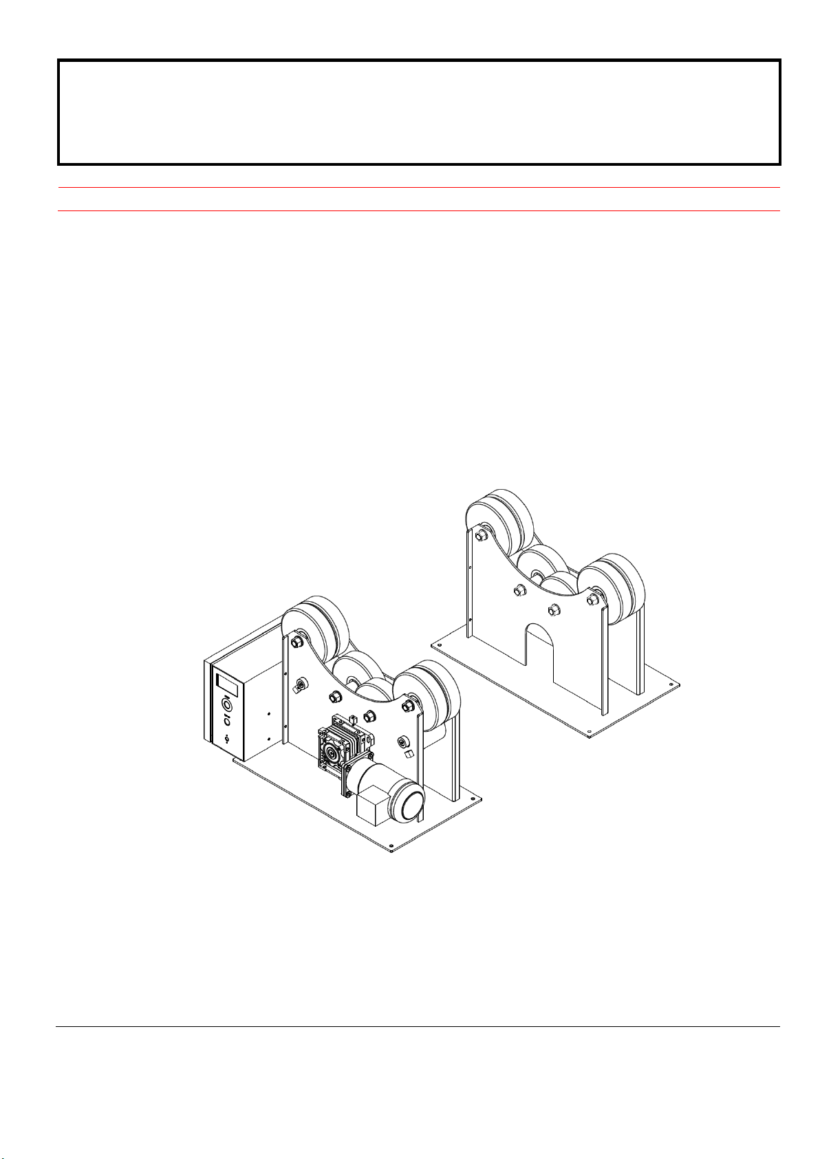
TURNING ROLL (Digital)
Serial Number
:
200907003 ~ Later
Revised Date: Sep. 18th, 2020
UNITED PROARC CORPORATION
No. 3 Gungye 10th Road, Pingjen Ind. Park, Tel No:88634696600
Pingjen City, Taoyuan 324, Taiwan Fax No:88634694499
http://www.proarc.com.tw E-Mail:customerservice@proarc.com.tw
RD-8447AE


TABLE OF CONTENTS
Introduction
Specification & installation
Operation
Trouble shooting guide
Parts list
Circuit diagram
Appendix
Instruction.................................................................................................i
Safety precautions...................................................................................ii
Limited warranty......................................................................................iii
1.1 Features............................................................................................1
1.2 Specification......................................................................................2
1.3 Installation.........................................................................................3
2.1 Remote control instruction.................................................................4
3.1 Trouble shooting guide......................................................................6
4.1.1 Parts list – Power roll (TR-3504P) ..................................................8
4.1.2 Parts list – Idler roll (TR-3504I).......................................................9
4.2 Parts list – Control box......................................................................10
5.1 Control circuit....................................................................................12
5.2 Control system box...........................................................................15
Inverter settings.................................................................................................16
Wiring diagram...................................................................................................18

i
INSTRUCTION
A procedure, which if not properly followed, may cause injury to the
operator or others in the operating area.
Read and understand this entire manual regarding the rules for users’
safety before installing, operating, or servicing the equipment.
Equipment Identification
Receipt of Equipment
The identification number specification or part number, model, and serial
number of this unit usually appear on a nameplate attached to the control panel
record these numbers for future reference.
When you receive the equipment, check it against the shipping documents.
Make sure it is complete and inspect the equipment for possible damage during
shipping. If there is any damage, notify the carrier immediately to file a claim.
Furnish complete information concerning damage claims or mistake(s) in
shipment to United ProArc Corporation:No. 3 Gungye 10th Road, Pingjen Ind.
Park, Pingjen City, Taoyuan 324, Taiwan. Include the equipment identification
number along with a description of the parts in question.
Move the equipment to the installation site before uncrating the unit. Use care
to avoid damaging the equipment when using bars, hammers, etc. to uncrate
the unit.
Falling machine due to lifting device failure may cause death or injury.
* Lifting device may fail when overloaded.
* Avoid sudden jerks, drops or swinging.
* Check lifting device components visually for looseness and signs of metal
fatigue.
WARNING
WARNING
WARNING

ii
SAFETY PRECAUTIONS
Operation and maintenance involves potential hazards. All operators
and personnel should be alerted to possible hazards and precautions
should be taken to prevent possible injury.
Electrical safety Machine:
﹡The counter, safety device against excess current and electrical installation, are
compatible with its maximum power and its main voltage.
﹡The connection, single-phase or three-phase, is possible on a stand compatible
with the plug of its cable link.
﹡If the cable is connected with the electrical network, the earth must never be cut
by the protection device against electrical shocks.
Work Place:
﹡Be very careful to avoid contact between metal part and phase conductor and the
neutral of electric network.
﹡Electrical messes of different electrical machine and apparatus are connected
between themselves and with the terminal of earth neutral wire.
Interventions:
﹡Before control and repair, see the apparatus is switched off and insulated.
﹡Connection with fixed installation cable is impossible.
﹡It’s on “Stop” and connection is impossible.
﹡Some apparatus are provided with starting circuit HT HF (with a plate). Never
enter into the corresponding switch cupboard.
﹡Only qualified persons are authorized for intervention concerning electrical
instillation.
WARNING

ii
SAFETY PRECAUTIONS
Maintenance
Individual safety
Gases and fumes
Fire
Noise
Protection goggle
*Often check the insulation and connection good state of apparatus and electrical
accessories:taps, appliance cords, coatings, switch, extension cords, etc.
﹡Maintenance and repair of insulating coatings operations are very important.
﹡Do repair with a specialist or better replace defective accessories.
﹡Check regularly the right adjustment and the non-heating of electrical
connections.
﹡The operator must be dressed and protected in relation with his work.
﹡Avoid contacting metal parts connected or accidentally connected.
﹡Wear leather gloves with gauntlet.
﹡Safety clothes: gloves, apron, safety shoes protect the operator and his
assistants against burns of hot parts, projections and slag.
﹡Gases and fumes produced during the plasma cutting or welding process can be
dangerous and hazardous to your health.
﹡Ventilation must be adequate to remove gases and fumes during operation.
﹡Keep all fumes and gases from the breathing area.
﹡Use an air supplied respirator if ventilation is not adequate to remove all fumes
and gases.
﹡Oil or grease in the presence of oxygen may ignite and burn violently. Keep
cylinders, valves, couplings, regulators, hoses, and other apparatus clean and
free from oil and grease. Oxygen cylinders and apparatus should not be handled
with oily hands or gloves. Do not allow an oxygen stream to contact oily or greasy
surfaces.
﹡Do not use oxygen as a substitute for compressed air.
﹡Fire can be caused by hot slag and sparks.
﹡Remove combustibles from working area or provide a fire watch.
﹡Do not cut containers that have held combustibles. Remove all flammable and
combustible materials in the operating area that may be ignited by sparks.
﹡Noise can cause permanent hearing loss.
﹡Wear proper protective ear muffs or plugs.
﹡Make sure others in the operating are protected from noise.
﹡Welding radiation may cause permanent sight damage
Eyes protection goggle recommended

iii
LIMITED WARRANTY
UNITED PROARC CORPORATION warrants all new equipment to be free from defects in material and
workmanship, provided that the equipment is installed and operated according to instructions stated in this
manual.
UNITED PROARC’s obligation under this warranty policy is expressly limited to the replace or repair, at its
option, of the defected part only. ProArc’s option to repair or replacement of a defected part under this
warranty shall be based on FOB Taiwan basis.
The warranty period begins on the date of sale to the original-purchase user of the equipment.
UNITED PROARC CORPORATION shall not be liable for any loss or consequential damage or express
accruing directly or indirectly from the use of equipment covered by this warranty.
This warranty supersedes all previous ProArc warranties and is exclusive with no other guarantees or
warranties expressed or implied.
This warranty excludes the consumable parts that are used in normal operation.

T
T
TH
H
HI
I
IS
S
S
P
P
PA
A
AG
G
GE
E
E
I
I
IS
S
S
B
B
BL
L
LA
A
AN
N
NK
K
K

1
1.1 FEATURES
Direct final positive gear drive.
Roll work range, from 9mm to 1200mm diameter, without changing wheel center.
“Forward / Stop / Reverse” switch with potentiometer for step less speed adjustment.
Ideal where pipe works for welding.
PU rubber tires provide friction drive and uniformly smooth pipe rotation.
2
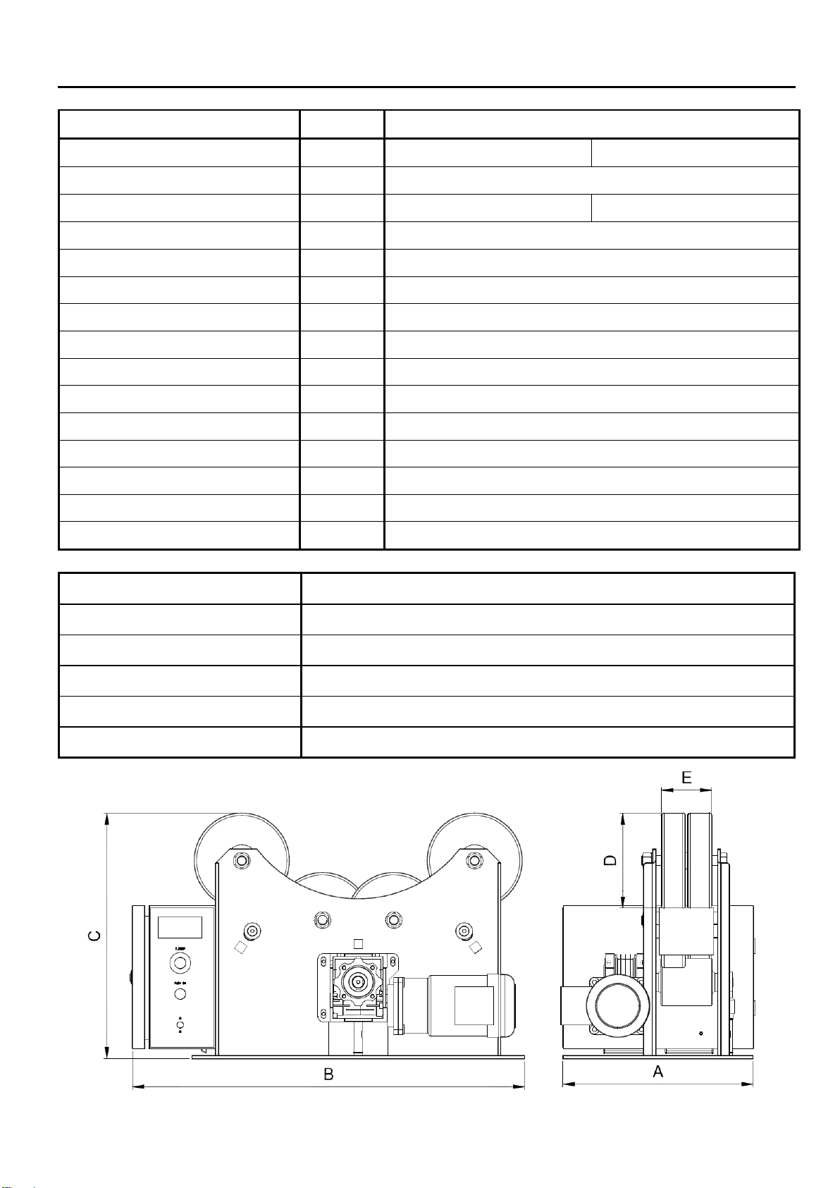
1.2 SPECIFICATION
Model Unit TR-3504
Power Input ~ 1 Phase 220V 50/60Hz 3 Phase 460V 50/60Hz
Rated Capacity KVA 0.5
NFB Capacity A 2 1
Turning Capacity kg 3,500
Load Capacity (Drive & Idler) kg 3,500
Diameter Range mm ψ9 ~ 1400
Speed Range mm/min 60 ~ 1200
Rotation Motor Hp 1/2
Roller DIA.(D) mm ψ200
Roller Width(E) mm 100
Roller Type - PU
Overall Width (A) (Driver/Idler) mm 425 / 280
Overall Length (B) (Drive/Idler) mm 780 / 700
Overall Height (C) mm 520
Net Weight (Drive/Idler) kg 165 (110 / 55)
Installation location Altitude 1000M or below , Free from corrosive gas and liquid.
Ambient temperature 0~+40℃(non-condensing and not frozen).
Ambient humidity Below 90%RH (non-condensing).
Storage temperature -20~+60℃(non-condensing and not frozen).
Storage humidity Below 90%RH (non-condensing).
International projection IP 22
3
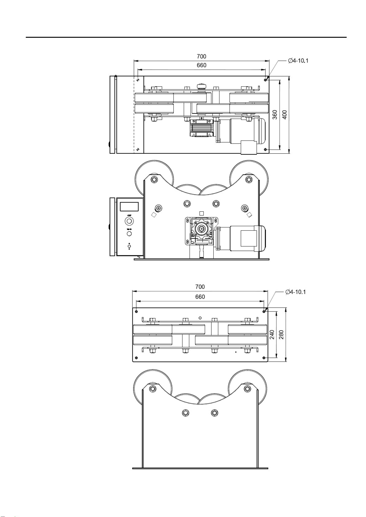
1.3 INSTALLATION
Power Roll
Idler Roll

4
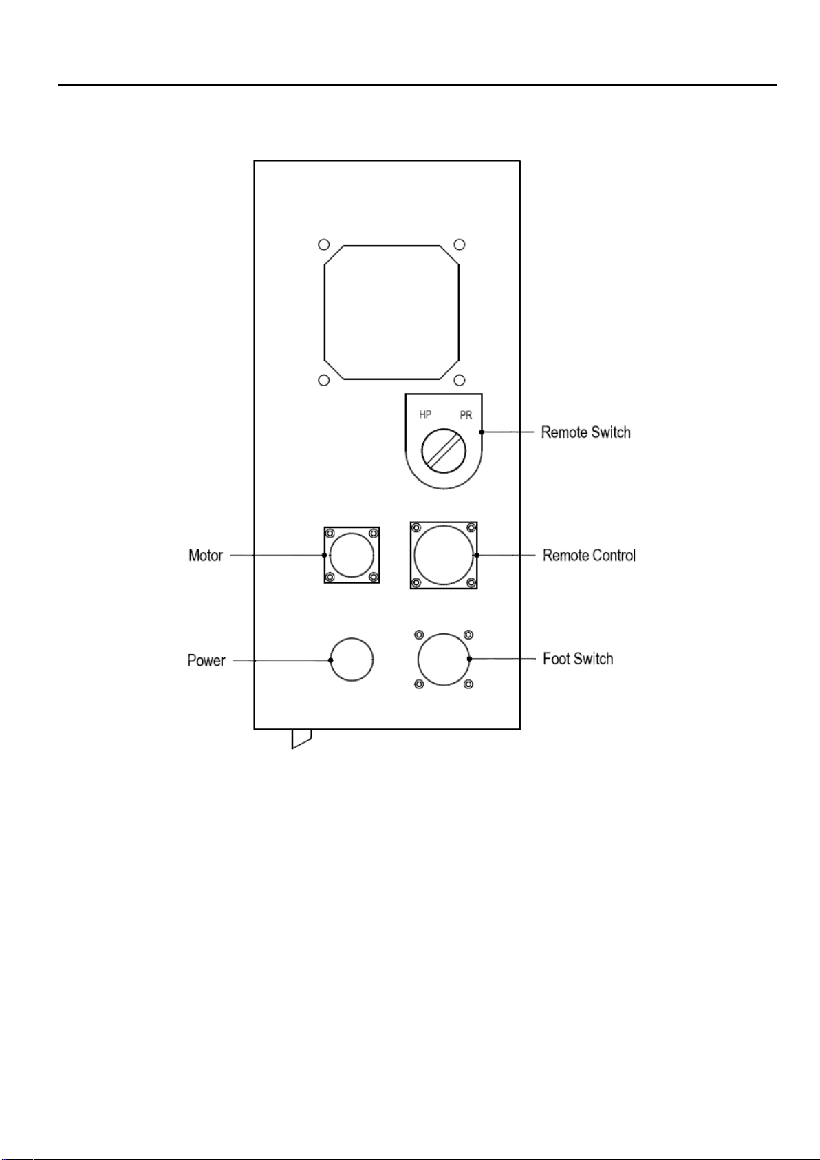
2.1 REMOTE CONTROL INSTRUCTION
1. Main power switch:System’s main power ‒NFB switch (circuit breaker).
2. “Start” switch:Press to start the system – green light.
3. Remote control device:
A. Speed meter.
Shows the speed data (Hz.)
B. Speed knob.
To increase speed, turn clockwise.
To decrease speed, turn counter clockwise.
C. Forward / Reverse
Indicates forward and reverse direction of the turning rollers.
CAUTION : [ WHILE TURNING, PLEASE AVOID CHANGING DIRECTION. ]
D. Run / Stop.
Set the “Forward / Reverse” direction followed by pressing the “Run” button to turn the rollers
continuously. Press “Stop” button to stop the turning.
E. Jog / Reset.
While the machine is not in motion, you can adjust to desired position slowly by pressing “Jog”
function. When the inverter driver displays an error message, press “Reset” to clear the error and
reset the system.
F. E-stop button.
Press the emergency stop button to terminate the driver circuit.
4.Line speed meter:Display 0 when the wheel is completely stopped. The line speed is displayed to
facilitate the wheel speed adjustment.
﹡
Please remove the external cover in order to set the RPM meter.
5
2.1 REMOTE CONTROL INSTRUCTION

6
3.1 TROUBLE SHOOTING GUIDE
SYMPTOM POSSIBLE CAUSE / REMEDY
1. After switch on, the power light
doesn't lit
A. NFB jumps off.
To check the main circuit-disconnect or short.
B. No power input.
To inspect the AC power input voltage and phase.
C. DC24V no output
(a)To inspect and make sure the switching power supply input
voltage is correct or not ?
(b)To Check the Fuse was burn down or not? If yes, please
replace new one.
D. Control PC board.
Please refer the item 2.
E. The indicator light breaks down.
(a)To make sure the voltage of indicator-DC24V.
(b)To inspect the indicator.
2. Control PC board indicator (LED
lamp) wasn't illuminated or
damaged.
A. AC or DC power input disconnected.
To inspect power input voltage and phase.
B. Fuse burn down.
To inspect the F1 & F2 fuse working or not, If damaged, please
replace a new one.
3. Inverter – no display.
A. Inverter has no power input.
Check if magnetic contactor is defective (replace).
B. Inverter has power input.
Check if inverter’s digital remote panel is defective (replace).
4. Inverter – displays ALM. A. Inverter driver display" ALM "data.
To make sure the display status, and refer the inverter driver
Trouble shooting.

7
3.1 TROUBLE SHOOTING GUIDE
SYMPTOM POSSIBLE CAUSE / REMEDY
5. The turntable has no movement.
A. Remote control breaks down.
Please refer the item 6.
B. Control PC board.
Please refer the item 2.
C. Inverter breaks down, no output.
Please refer the item 3 & 4.
D. Failed motor
Check / change a new motor.
E. The reducer is damaged.
Replace a new reducer.
6. Remote switch has no action
A. Snap switch damaged.
To check the snap switch connector is normal or not? And
replace it.
B. Indicator was no work.
To change the indicator.
8
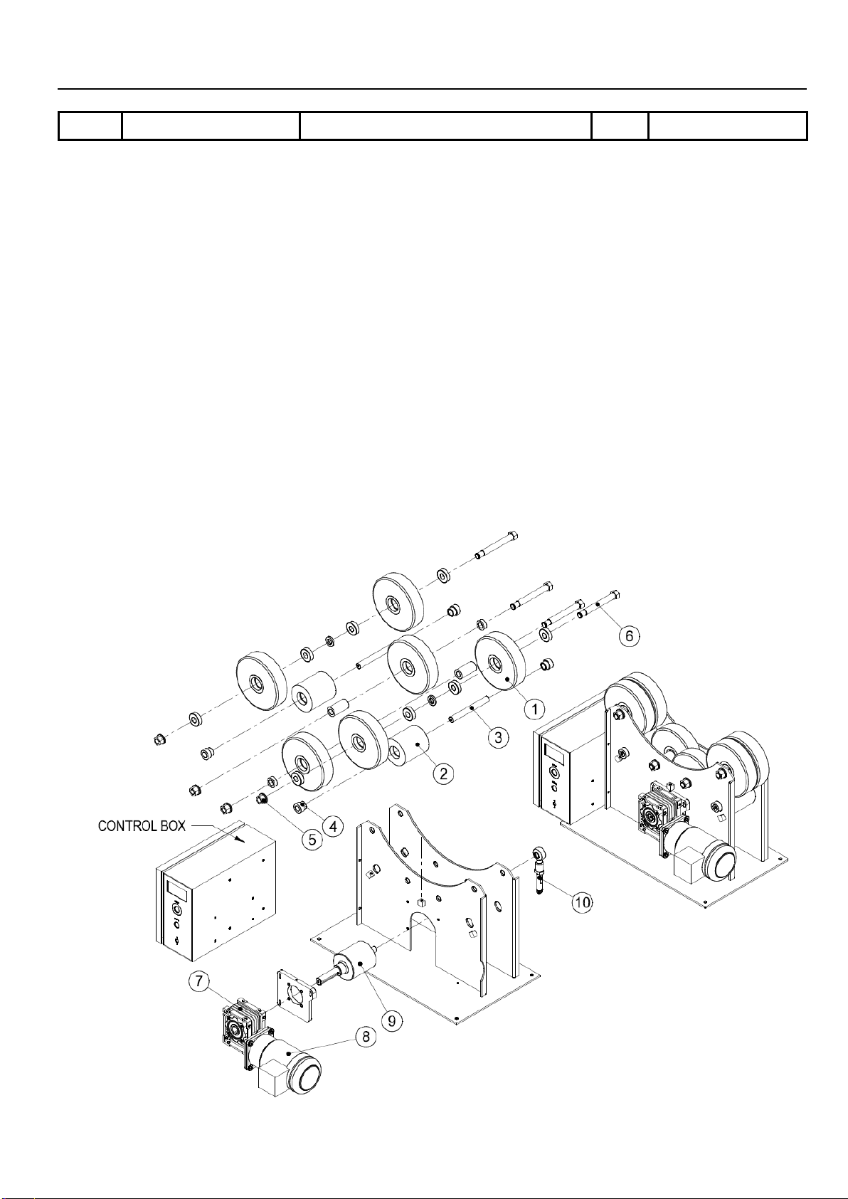
4.1.1 PARTS LIST ―POWER ROLL (TR-3504P)
Item.
Part No.
Description
Q’ty.
Remark
1 *
5041-1030000-10 PU roller with bearing 6 Roll & Bearing
*
5041-1030100-10 PU roller 1
*
0301-0403
Bearing
2
2 5045-1560100-10 Friction wheel 2
3 5045-1560200-10 Friction shaft 2
4 0301-0403 Deep-Groove ball bearing 4
5 0123-2000 Hex nut 4
0122-2000
Spring washer
4
6 5045-1540300-10 Screw 4
7 *
0353-0303 Worm reducers 1
8
*
0350-0045
Reducer motor
1
9
5045-1570000-22 Driving roller 1
10 *
0311-2001 Joint bearing 1
*Recommended spare parts

9
4.1.2 PARTS LIST ―IDLER ROLL (TR 3504I)
Item. Part No. Description Q’ty. Remark
1 *
5041-1030000-10 PU roller with bearing 6 Roll & Bearing
*
5041-1030100-10 PU roller 1
0301-0403 Bearing 2
2 5045-1540300-10 Screw 4
3 0123-2000 Hex nut 4
0122-2000 Spring washer 4
*Recommended spare parts

10
4.2 PARTS LIST ―CONTROL BOX
Item.
Part No.
Description
Q’ty.
Remark
1
3061-1006
Line speed meter
1
2
3214-2002
E.S Push Button
1
3214-1005
Contact
1
3
3214-4006
Push button (w/ light)
1
PB1
4
3216-1003
Rotary switch
1
5
*
3323-0005
Power supply
1
PS
6
*
3224-1005
Magnetic contactor
1
MC
7
3221-2003
No Fuse breaker
1
With AC220V
3221-3008
No Fuse breaker
1
With 4AC60V
8
*
6652-1221
PC Board
1
PCB
9
3021-2101
Inverter
1
INV ( With AC220V )
3021-4101
Inverter
1
INV ( With AC460V )
10
3311-0018
Transformer
1
With AC460V
11
3071-2201
Fan
1
With AC460V
12
3211-4105
Select switch
1
Options for VSFC
13
3122-4004
Socket female 10Pin
1
Options for VSFC
14
3122-7002
Socket female 17 Pin
1
JN4
15
3122-4003
Female male connector 7 Pin
1
JN2
16
3023-0003
Pendant Inverter 7.5M
1
7.5M
*
3457-4007
Pendant Inverter cable
1
JN4
*Recommended spare parts

11
T
T
TH
H
HI
I
IS
S
S
P
P
PA
A
AG
G
GE
E
E
I
I
IS
S
S
B
B
BL
L
LA
A
AN
N
NK
K
K

12
5.1 CONTROL CIRCUIT (1ψ220V)
Table of contents
Other ProArc Industrial Equipment manuals


