Procentec ProfiTrace 2.9 User manual

ProfiTrace 2.9
User Manual

ProfiTrace 2.9 User Manual V5.0.4 | April 18 | © PROCENTEC 2/149
Safety Guidelines
This manual contains notices which you should observe to ensure your own personal safety, as well as to
protect the product and connected equipment. These notices are highlighted in the manual by a warning sign
and are marked as follows according to the level of danger:
Draws your attention to important information on handling the product, a particular part of the
documentation or the correct functioning of the product.
Warning
This device and its components may only be used for the applications described in this manual and only in
connection with devices or components that comply with PROFIBUS and RS-485 interface.
This product can only function correctly and safely if it is transported, stored, set up, installed, operated and
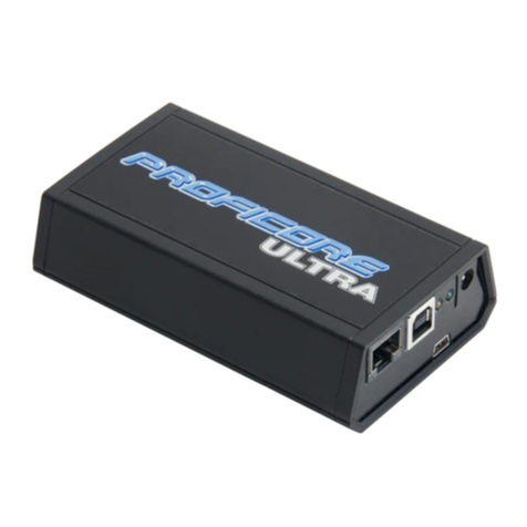
maintained as recommended. The ProfiCore Ultra is a CE class A product. In a domestic environment it may
cause radio interference in which case the user may be required to take adequate measures.
Warranty
Warranty is void if you open ProfiCore Ultra.
Disclaimer of Liability
We have checked the contents of this manual as much as possible. Since deviations cannot be precluded
entirely, we cannot guarantee full agreement. However, the content in this manual is reviewed regularly and
necessary corrections will be included in subsequent editions. Suggestions for improvements are welcome.
Copyright © 2011-2018 PROCENTEC
All rights reserved. No part of this publication may be reproduced, stored in a retrieval system, or transmitted,
in any form or by any means, electronic, mechanical, photocopying, recording or otherwise, without the prior
written permission of the publisher.
ProfiCore is a registered trademark of PROCENTEC. Other products or company names are or may be registered
trademarks and are the property of their respective companies.

ProfiTrace 2.9 User Manual V5.0.4 | April 18 | © PROCENTEC 3/149
Important information
Purpose of the Manual
This user manual provides information how to work with ProfiTrace 2.
Recycling and Disposal
The parts of the ProfiCore Ultra can be recycled. For further information about environment-friendly recycling
and the procedure for disposing of your old equipment, please contact:
Document Updates
You can obtain constantly updated information on PROCENTEC products on the Internet at
www.procentec.com
You can also contact PROCENTEC Customer Support:
•by phone at +31-(0)174-671800
•by fax at +31-(0)174-671801
•by email at support@procentec.com
PROCENTEC
Klopperman 16
2292 JD WATERINGEN
The Netherlands
T: +31-(0)174-671800
F: +31-(0)174-671801

ProfiTrace 2.9 User Manual V5.0.4 | April 18 | © PROCENTEC 4/149
Contents
Important information .................................................................................................................... 3
1. Product description ............................................................................................................... 7
1.1. Introduction...................................................................................................................................... 7
1.2. Product features ............................................................................................................................... 8
1.3. Application areas .............................................................................................................................. 8
1.4. Detectable faults on PROFIBUS DP ................................................................................................... 9
1.5. Detectable faults on PROFIBUS PA ................................................................................................. 10
1.6. System requirements...................................................................................................................... 11
1.7. ProfiTrace structure........................................................................................................................ 12
2. ProfiCore Ultra..................................................................................................................... 13
2.1. Internal structure............................................................................................................................ 13
2.2. Support-power connectors............................................................................................................. 14
2.2.1. Micro-USB connection.................................................................................................................... 14
2.2.2. Adapter........................................................................................................................................... 14
2.3. Expansion connector ...................................................................................................................... 14
3. Software installation instructions (Windows 7, 8, 10)....................................................... 15
3.1. Installation procedure .................................................................................................................... 15
3.2. Prior to installation ......................................................................................................................... 15
3.3. Setup program................................................................................................................................ 16
3.4. ProfiCore Ultra driver installation................................................................................................... 16
3.5. ProfiTrace installation..................................................................................................................... 17
3.6. Connecting ProfiCore Ultra to the USB port................................................................................... 20
3.7. Directories ...................................................................................................................................... 22
3.8. Selecting the language of the user interface.................................................................................. 23
3.9. Installing GSD files in ProfiTrace ..................................................................................................... 24
3.10. Installing GSD files in ProfiCaptain ................................................................................................. 25
3.11. Setting color preferences ............................................................................................................... 26
3.12. Upgrades......................................................................................................................................... 27
4. License system..................................................................................................................... 28
4.1. Introduction.................................................................................................................................... 28
4.2. Characteristics of the license file name.......................................................................................... 28
4.3. Storage location of the license files................................................................................................ 28
4.4. Obtaining the license files .............................................................................................................. 29
4.5. Requesting a Trial License .............................................................................................................. 31
4.6. Activating a Trial License ................................................................................................................ 31
5. Quick start............................................................................................................................ 33
5.1. Attaching ProfiCore Ultra to the installation .................................................................................. 33
5.1.1. Attach the Tap Connector to the ProfiCore (DP). ........................................................................... 33
5.1.2. Attaching the ProfiCore to the DP installation ............................................................................... 34
5.1.3. Attaching the PA Probe to the ProfiCore........................................................................................ 35
5.1.4. Attaching the PA Probe to the PA installation................................................................................ 36
5.2. Starting ProfiTrace 2 ....................................................................................................................... 37
5.3. Busmonitor/Analyzer...................................................................................................................... 39
5.3.1. Live List ........................................................................................................................................... 40
5.3.2. Statistics.......................................................................................................................................... 41
5.3.3. Message recording ......................................................................................................................... 44
5.3.4. Data inspection............................................................................................................................... 45
5.4. Network Condition Indicator .......................................................................................................... 46
5.5. ScopeWare...................................................................................................................................... 47
5.6. Bar graph ........................................................................................................................................ 48
5.6.1. Bar graph Modes ............................................................................................................................ 50

ProfiTrace 2.9 User Manual V5.0.4 | April 18 | © PROCENTEC 5/149
5.7. Topology scan ................................................................................................................................. 51
5.7.1. Restrictions for using the topology scan ........................................................................................ 52
5.8. Cable length measurement ............................................................................................................ 52
5.9. Network Manager........................................................................................................................... 54
5.10. ProfiCaptain .................................................................................................................................... 54
5.11. Report generation .......................................................................................................................... 56
6. Message and file recording................................................................................................. 58
6.1. Message columns ........................................................................................................................... 59
6.1.1. Attention column............................................................................................................................ 61
6.1.2. Frame column................................................................................................................................. 62
6.1.3. Service column (for requests)......................................................................................................... 62
6.1.4. Service column (for responses) ...................................................................................................... 63
6.1.5. Msg Type values ............................................................................................................................. 64
6.2. File recording .................................................................................................................................. 65
7. Network Condition Indicator............................................................................................... 67
7.1. Measurement time and reset button............................................................................................. 67
7.2. PROFIBUS Traffic Light and warnings ............................................................................................. 67
7.3. Risk Margin ..................................................................................................................................... 68
7.4. Network summary .......................................................................................................................... 68
8. Wizard .................................................................................................................................. 69
8.1. Accessing the Wizard features ....................................................................................................... 69
8.2. Wizard: ‘Gather Network Info’ ....................................................................................................... 69
8.3. Wizard: ‘Trouble finder’................................................................................................................. 70
8.4. Wizard: ‘Scan Inactive Network’..................................................................................................... 71
9. Oscilloscope measurements (RS-485 –DP) ....................................................................... 72
9.1. Acceptable signals .......................................................................................................................... 72
9.2. Termination missing or wire break................................................................................................. 73
9.3. Short circuit between A and B ........................................................................................................ 74
9.4. Short circuit between B and Shield................................................................................................. 75
9.5. Too many terminators .................................................................................................................... 76
9.6. Not powered termination............................................................................................................... 77
9.7. EMC/EMI......................................................................................................................................... 78
10. Oscilloscope measurements (MBP –PA)............................................................................ 79
10.1. Acceptable signals .......................................................................................................................... 79
11. Network Manager................................................................................................................ 80
11.1. Edit station properties.................................................................................................................... 80
11.2. View Bar Graph............................................................................................................................... 81
11.3. View individual scope signals ......................................................................................................... 82
11.3.1.User Scope Image ........................................................................................................................... 82
11.4. Topology Scan................................................................................................................................. 82
11.5. Saving, loading and resetting.......................................................................................................... 82
11.6. Creating a new measuring point..................................................................................................... 83
11.7. Creating a new segment ................................................................................................................. 84
11.8. Rearranging segments .................................................................................................................... 85
12. ProfiCaptain ......................................................................................................................... 87
12.1. Setting up the DP Master ............................................................................................................... 87
12.1.1.Manual busparameter setting ........................................................................................................ 88
12.1.2.Automatic busparameter detection ............................................................................................... 89
12.1.3.Activate the DP master................................................................................................................... 90
12.2. Class 2 DP-V0 functions .................................................................................................................. 91
12.2.1.Network scan.................................................................................................................................. 91
12.2.2.Set Slave Address............................................................................................................................ 92
12.2.3.Read Input & Read Output ............................................................................................................. 93
12.2.4.Get Configuration ........................................................................................................................... 94

ProfiTrace 2.9 User Manual V5.0.4 | April 18 | © PROCENTEC 6/149
12.2.5.Get Diagnostics............................................................................................................................... 94
12.3. Configuring slave devices ............................................................................................................... 95
12.3.1.Filtering GSDs.................................................................................................................................. 95
12.3.2.Adding devices................................................................................................................................ 95
12.3.3.Status of the device ........................................................................................................................ 97
12.3.4.Info on Stealing slaves .................................................................................................................... 98
12.4. Exchanging I/O data........................................................................................................................ 98
12.4.1.Data types....................................................................................................................................... 99
12.4.2.Visualization types........................................................................................................................ 100
12.4.3.Automatic patterns....................................................................................................................... 100
13. OPC server.......................................................................................................................... 101
13.1. Installing the OPC drivers ............................................................................................................. 101
13.2. Selecting OPC tags ........................................................................................................................ 102
13.3. Activating the OPC server ............................................................................................................. 103
14. CommDTM......................................................................................................................... 106
14.1. Installing the drivers and DTM server........................................................................................... 106
14.2. Setting up the PCD server............................................................................................................. 107
14.3. Using the CommDTM ................................................................................................................... 107
15. Training............................................................................................................................... 109
15.1. First steps...................................................................................................................................... 109
15.2. ProfiTrace Live List........................................................................................................................ 111
15.3. ProfiTrace Statistics ...................................................................................................................... 111
15.4. Recording messages ..................................................................................................................... 113
15.5. Data inspection............................................................................................................................. 114
15.6. Oscilloscope.................................................................................................................................. 114
15.7. Bar graph ...................................................................................................................................... 115
15.8. Report generation ........................................................................................................................ 115
15.9. ProfiCaptain .................................................................................................................................. 116
16. Tips and tricks .................................................................................................................... 117
16.1. Checklist to prepare your installation........................................................................................... 117
16.2. Checklist to create a reliable installation...................................................................................... 118
16.3. How can I 'self-test' ProfiTrace and the ProfiCore Ultra?............................................................. 118
16.4. ProfiTrace and ProfiCaptain secrets ............................................................................................. 119
17. Technical data ProfiCore Ultra.......................................................................................... 120
18. Technical data PA Probe Ultra .......................................................................................... 122
19. Technical data Tap Connector .......................................................................................... 123
20. Hotkeys............................................................................................................................... 124
21. Frequently asked questions .............................................................................................. 125
22. Products and spare parts .................................................................................................. 130
23. Contents of the Troubleshooting Toolkit ......................................................................... 132
24. Glossary.............................................................................................................................. 133
25. Revision History ................................................................................................................. 139
27. Sales offices and Distributors............................................................................................ 140
28. About PROCENTEC............................................................................................................. 146
29. Notes .................................................................................................................................. 147

ProfiTrace 2.9 User Manual V5.0.4 | April 18 | © PROCENTEC 7/149
1. Product description
1.1. Introduction
ProfiTrace 2 is the most powerful mobile analyzer for
PROFIBUS networks. It is the latest generation in the
line of busmonitor technology. Thousands of users
benefit daily from this great tool. ProfiTrace combines
all required tools in one:
•Busmonitor
•Oscilloscope
•Bar Graph
•Topology Scan
•Reporting
•DP Master
Technicians can check and troubleshoot the complete
PROFIBUS network with 1 software package and 1 piece
of hardware. An enormous reduction in equipment,
weight, costs and required knowledge.
The advanced USB hardware (ProfiCore™Ultra) is internally equipped with a high-speed digital oscilloscope
and able to capture bus signals running at 12 Mbps. It can also be used on PROFIBUS PA installations with the
PA Probe Ultra.
ProfiTrace is an essential tool for maintenance, commissioning and troubleshooting as well as product
development. Typical failures such as noise, reflections, voltage drops, termination problems, double
addresses, wire breaks and configuration faults are easily identified. Random errors such as overshoots, error
telegrams, repeats and diagnostics can also be captured and logged. The results can be exported to detailed
reports which are accepted by the industry. Predictive maintenance and asset management are really possible
with ProfiTrace.
This revolutionary tool has been developed because of technological limitations of other available tools on the
market. The service team of PROCENTEC was frequently forced to invest heavily in interface cards and
eventually could no longer accept the frustrations of PC locked licenses. That the prices of the tools are
relatively high and the displayed information is too complex was another contributing factor. Therefore
PROCENTEC decided to initiate the development of a tool that was ideally suited to our needs and those of the
end-user.
This outstanding tool that fits in your pocket will boost the capabilities of service, maintenance and engineering
technicians.

ProfiTrace 2.9 User Manual V5.0.4 | April 18 | © PROCENTEC 8/149
1.2. Product features
•Busmonitor for DP and PA with powerful statistics
Repeats, fall-outs, corrupted messages, diagnostics, cycle time, etc.
•High-speed digital oscilloscope - ScopeWare
Differential voltage, A-line, B-line, noise, overshoots, reflections, triggers.
•Bar graph
Average, Min. and Max. values of the bus signals per device.
•Topology Scan
Automatic generation of the network topology.
•Cable length measurement
Calculation of the length of one segment.
•Reporting
Automatic generation of detailed reports that are accepted by the industry.
•DP master - ProfiCaptain
A complete DP master has been integrated (V0 and V1).
•ProfiCore™Ultra USB interface
Useable on PC platforms, no power supply required and elimination of spur lines.
•OPC server and CommDTM
•XP, Vista and Windows 7, 8 and 10 platforms
•Multi language user interface
1.3. Application areas
•Troubleshooting & maintenance of PROFIBUS networks
(ProfiTrace, ScopeWare, Topology scan and ProfiCaptain)
•Commissioning of PROFIBUS networks
(ProfiTrace, ScopeWare, Topology scan and ProfiCaptain)
•PROFIBUS product testing and verification
(ProfiTrace, ScopeWare, ProfiCaptain and CommDTM)
•Passive cable testing
(ScopeWare and ProfiCaptain)
•I/O testing of PROFIBUS devices
(ProfiCaptain)
•Setting up and diagnose PROFIBUS devices
(CommDTM)
•Address setting of PROFIBUS devices
(ProfiCaptain)
•Interface for bus statistics and device I/O to external apps
(OPC server)
•Education

ProfiTrace 2.9 User Manual V5.0.4 | April 18 | © PROCENTEC 9/149
1.4. Detectable faults on PROFIBUS DP
ProfiTrace 2 can be used to detect almost all faults in PROFIBUS DP networks. The table below describes the
sub-programs you need to find specific faults.
Faults on DP
Passive cable
(No devices connected)
No master active
(Slaves are connected)
Running
installation
General communication
faults
ProfiCaptain + ProfiTrace
ProfiTrace
Double address
ProfiCaptain + ProfiTrace
ProfiTrace
Wrong address
ProfiCaptain
ProfiTrace
Missing device
ProfiCaptain
ProfiTrace
Device diagnostics
ProfiCaptain
ProfiTrace
Configuration faults
ProfiCaptain
ProfiTrace
No termination
ProfiCaptain + ScopeWare
ProfiCaptain + ScopeWare
ScopeWare
Too many termination
ProfiCaptain + ScopeWare
ProfiCaptain + ScopeWare
ScopeWare
Powerless termination
ScopeWare
ScopeWare
ScopeWare
Spur lines
ProfiCaptain + ScopeWare
ScopeWare
Short-circuit, break,
crossed wires
ProfiCaptain + ScopeWare
ProfiCaptain + ScopeWare
ScopeWare
Cable too long
ProfiTrace Cable
Measurement
ProfiTrace Cable
Measurement
ScopeWare
EMC/noise problems
ScopeWare
ScopeWare
ScopeWare
1 Meter rule
ProfiCaptain + ScopeWare
ScopeWare

ProfiTrace 2.9 User Manual V5.0.4 | April 18 | © PROCENTEC 10/149
1.5. Detectable faults on PROFIBUS PA
ProfiTrace 2 in combination with the PA Probe Ultra can be used to detect almost all faults in PROFIBUS PA
networks. The table below describes the sub-programs you need to find specific faults (it is assumed that the
PA network has a link+coupler and the ProfiTrace is connected to the PA segment):
Faults on PA
Running installation or a link that
communicates autonomously
General communication faults
ProfiTrace
Double address
ProfiTrace or ScopeWare
Wrong address
ProfiTrace
Missing device
ProfiTrace
Device diagnostics
ProfiTrace
Configuration faults
ProfiTrace
PROFIBUS DP connection failure
ProfiTrace
Bad status byte
ProfiTrace
No termination
ScopeWare
Too many termination
ScopeWare
Short-circuit, break, crossed wires
ScopeWare
EMC/noise problems
ScopeWare
DC Voltage too low/high
ScopeWare
Coupler (power) failure
ScopeWare

ProfiTrace 2.9 User Manual V5.0.4 | April 18 | © PROCENTEC 11/149
1.6. System requirements
In order to use ProfiTrace 2 and all sub programs, your computer system should include the hardware and
software listed below:
Minimum requirements:
•Microsoft Windows XP, Vista, 7, 8 or 10
•600 MHz Intel Pentium III processor or equivalent
•256 MB of RAM
•100 MB of available disk space
•1024 x 768 resolution display
•1 free USB 2.0 high-speed interface port supplying 400 mA
•1 Mouse or other pointing device
Recommended (differences to minimum):
•1 GHz Intel Pentium III processor or equivalent
•512 MB of RAM
•1280 x 1024 resolution display or better
Attention Users of Windows 98, 98 Second Edition and Millennium (Me)
PROCENTEC is not able to offer software downloads or replacement USB sticks for Windows 98, 98 Second
Edition (SE) or Windows Millennium (Me) for ProfiTrace 2. Microsoft has stopped supporting these operating
systems, and this change involves all suppliers.
If you received a USB stick that lists any of these operating systems on the label, be sure to keep it in a safe
place since it will no longer be available from PROCENTEC.
NOTE: The information in this document version supersedes any information in the digital or printed
documentation. Although the software for Windows 98, 98 Second Edition, and Windows Me will no longer be
available, it could be that ProfiTrace 2 works with these operating systems.

ProfiTrace 2.9 User Manual V5.0.4 | April 18 | © PROCENTEC 12/149
1.7. ProfiTrace structure
All processes of ProfiTrace run parallel. The user can easily switch to a process and inspect the information.
Record
trigger
Messages
(with view filter)
PC / Laptop / Windows
ProfiTrace+ ProfiCore Ultra
ProfiTrace user interface
Recordfilter
Messagefile
Network
manager
Livelist
Analyzer
Master
statemachine
ProfiCaptain
View filterMessages
Oscilloscope
Networkdata file
Topologyscan
Bargraph
ScopeWare
OPC server
Statistics
Datainspection
Fig. 1 - ProfiTrace processes

ProfiTrace 2.9 User Manual V5.0.4 | April 18 | © PROCENTEC 13/149
2. ProfiCore Ultra
The ProfiCore Ultra is the required hardware to use ProfiTrace 2. It has a robust industrial housing and
translates PROFIBUS to USB and vice versa. Because of the USB interface, ProfiTrace 2 can be used on field
laptops as well as desktop PCs.
The USB interface also eliminates spur lines. ProfiTrace 2 can be connected almost directly to the bus line and
the laptop positioned on a distance. This is a perfect measurement solution for high-speed networks.
•When ProfiTrace 2 is in the analyzer mode, it passively records the data traffic. It does NOT behave as a
master or slave.
•When ProfiCaptain is activated, the ProfiCore Ultra acts as a master and transmits messages on the bus.
2.1. Internal structure
ProfiCore Ultra has an isolated RS-485 interface (DB9 connector) and is equipped with a high-speed digital
oscilloscope that is able to capture bus signals running at 12 Mbps (see Fig. 2).
It can also be used on PROFIBUS PA installations with the PA Probe Ultra.
The RS-485 driver is 1/5th of a standard PROFIBUS busload. The chance of disturbing a working installation is
therefore reduced to a minimum.
ProfiCore Ultra has the capability to cache data in its on-board memory in case of Windows performance
problems or 'higher' priority tasks like the hard-disk. ProfiCore Ultra will NOT lose a single message.
PROFIBUS
Connector USB
Connector
Expansion
Connector
Support
Power
FPGA
Isolated
RS 485 - DP
Interface
USB
Technology
RAM/Cache Expansion
Technology
High Speed
Oscilloscope
Fig. 2 - Internal structure of the ProfiCore Ultra

ProfiTrace 2.9 User Manual V5.0.4 | April 18 | © PROCENTEC 14/149
2.2. Support-power connectors
If your laptop/PC is for some reason not able to supply the power to the ProfiCore, there are 2 options;
2.2.1. Micro-USB connection
This requires an additional USB port of your laptop/PC. The Micro-USB cable is provided with the
Troubleshooting Toolkit.
2.2.2. Adapter
The adapter has to supply 9 V - 500 mA with a power plug according to: NES/J 21, NES/J 21 W, NES/J 210
XNES/J 210. The adapter is NOT supplied with the product.
Plug information:
Opening: 6.0 mm
Center pin: 1.95 mm
2.3. Expansion connector
ProfiCore Ultra has an expansion connector (RJ 45) which can be used for all kinds of additional functionality.
ProfiTrace 2 uses the expansion connector to trigger an additional external oscilloscope.
In normal cases ProfiCore Ultra does NOT require an additional power supply because of the USB
connection.

ProfiTrace 2.9 User Manual V5.0.4 | April 18 | © PROCENTEC 15/149
3. Software installation instructions (Windows 7, 8, 10)
This chapter describes the installation for ProfiTrace 2 and the ProfiCore Ultra drivers. It is assumed that you
have a basic knowledge of Windows operating systems. All example and dialogs are based on a US/UK based
Windows installation and may differ slightly based on upgrades, updates and enhancements. Please use the
screenshots in conjunction with the description in order to press the appropriate buttons and other user
interface items.
It is possible to install ProfiTrace 2 next to ProfiTrace 1, they are both using another default installation
directory and the drivers are different. You can even run both applications at the same time.
3.1. Installation procedure
The installation of ProfiTrace has to be done with the following procedure:
Preparations prior to installation.
Installing the ProfiCore Ultra driver.
Installing ProfiTrace.
Connecting the ProfiCore Ultra to the USB port.
Installing GSD files in ProfiTrace and ProfiCaptain.
Setting color preferences.
3.2. Prior to installation
Prior to installation, follow the steps below:
Make sure you always use the latest version of ProfiTrace and ProfiCore Ultra drivers. Updates can be
downloaded from: www.procentec.com.
Install the latest service packs and ‘hot fixes’ for Windows.
Boot the PC in the normal mode of Windows (NOT in the safe mode).
Under multi-user versions/installations of Windows make sure you have administrator rights.
Do NOT connect the ProfiCore Ultra to the USB port (yet).

ProfiTrace 2.9 User Manual V5.0.4 | April 18 | © PROCENTEC 16/149
3.3. Setup program
Insert the ProfiTrace credit card USB stick in a free port and/or start Setup.exe. The install shield will display an
introduction screen (see next screenshot).
Click “Install” to install ProfiTrace and the ProfiCore Ultra driver. If you only want to install one of them, just
unselect the option you want to skip.
3.4. ProfiCore Ultra driver installation
The install shield will first install the ProfiCore Ultra driver. In a window the results of the installation can be
followed. Blue letters are OK, red letters indicate a problem. The driver can also be installed manually by
starting “DriverInstall.exe”.

ProfiTrace 2.9 User Manual V5.0.4 | April 18 | © PROCENTEC 17/149
3.5. ProfiTrace installation
After the ProfiCore Ultra driver has been installed the setup procedure continues with the installation of
ProfiTrace.
Click “Next” to proceed.
You have to accept the terms of the license agreement.
Click “Next” to proceed.

ProfiTrace 2.9 User Manual V5.0.4 | April 18 | © PROCENTEC 18/149
Select your destination folder.
Click “Next” to proceed.
Select startup folder.
Click “Next”.

ProfiTrace 2.9 User Manual V5.0.4 | April 18 | © PROCENTEC 19/149
Click “Next”.
Click “Finish” to close the install shield.
After the installation process, ProfiTrace is ready for use, however we recommend rebooting the PC.

ProfiTrace 2.9 User Manual V5.0.4 | April 18 | © PROCENTEC 20/149
3.6. Connecting ProfiCore Ultra to the USB port
After connecting the ProfiCore Ultra to the USB port, the last installation process will start.
Click “Next” to proceed.
Select the location of the drivers. Normally the first option is sufficient.
Click “Next” to proceed.
Table of contents
Other Procentec Measuring Instrument manuals
Popular Measuring Instrument manuals by other brands
Dilog
Dilog CombiVolt DL6780 instruction manual
Sensor Therm
Sensor Therm METIS M311 user manual

Ono Sokki
Ono Sokki HT-3200 instruction manual
Isotech
Isotech SLM 52N instruction manual
cliMATE
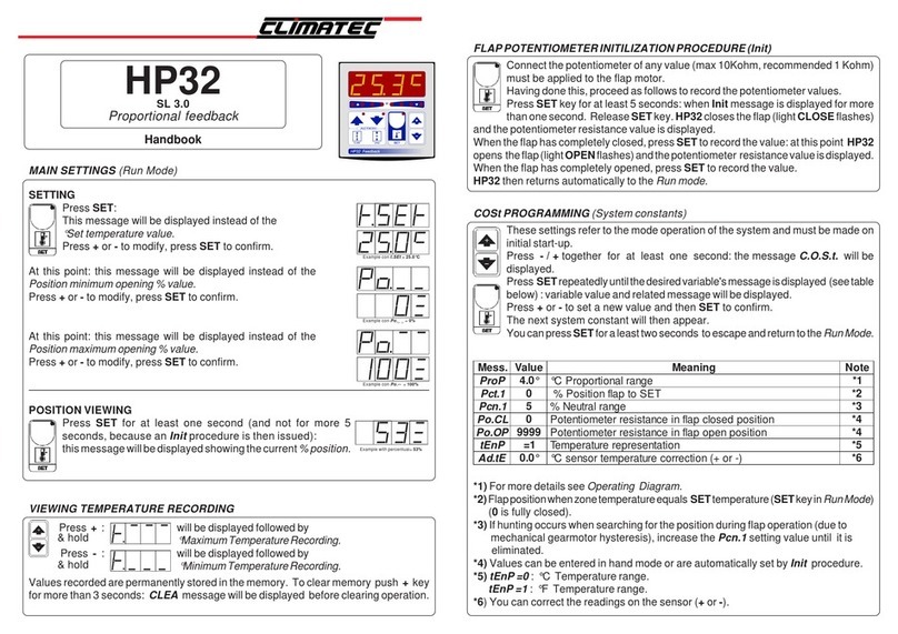
cliMATE HP32 Handbook
Kyoritsu Electrical Instruments Works, Ltd.
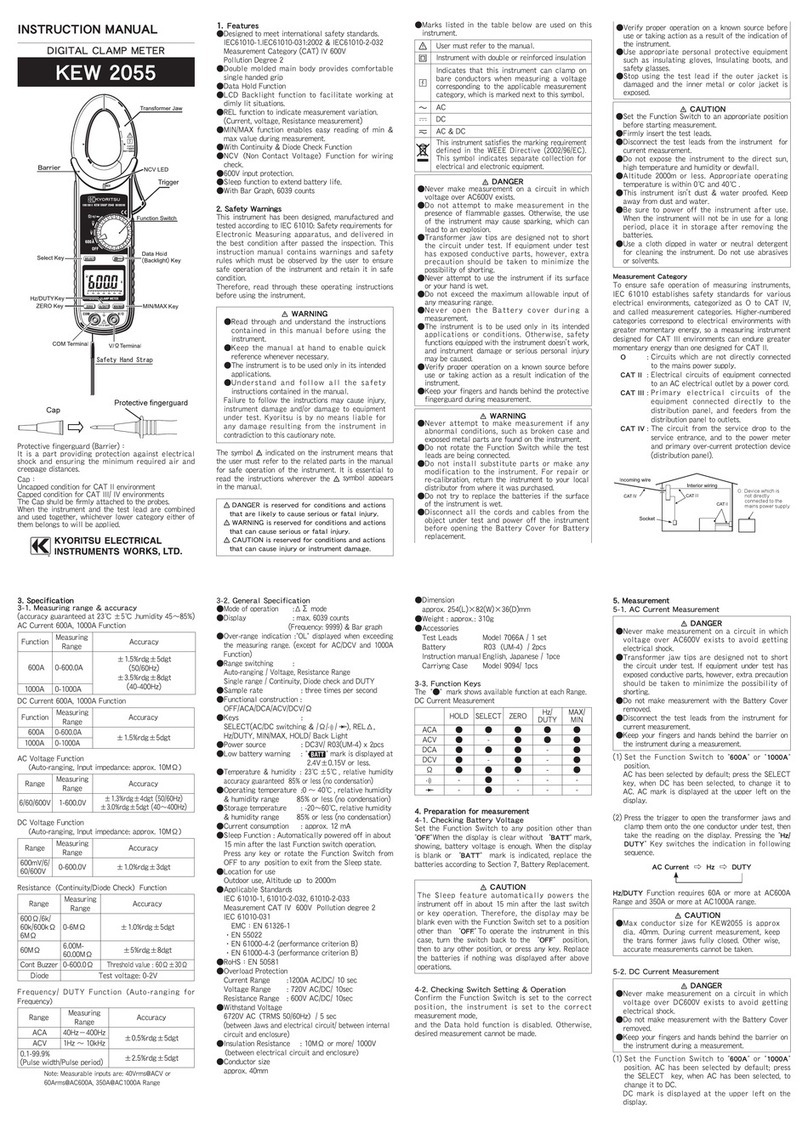
Kyoritsu Electrical Instruments Works, Ltd. KEW 2055 instruction manual
