manuals.online logo
Brands
  1. Home
  2. •
  3. Brands
  4. •
  5. PROception
  6. •
  7. Amplifier
  8. •
  9. PROception proMHD14R Operation and maintenance manual

PROception proMHD14R Operation and maintenance manual

Page 1Page 4
PD2011-9030-02
PROception
Proception Limited,
177-187 Rutland Road
SHEFFIELD
S3 9PT
United Kingdom
eb: http://www.proception.co.uk/
e-mail: [email protected]
Performance data given are typical unless otherwise stated. Proception Limited reserves the
right to change product designs and specifications without prior notice.
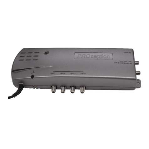
proMHD14R
Dual-mode
4-Way Outdoor UHF Amplifier
2-Year Guarantee
This guarantee covers failure of your PROception product resulting from manufacturing
defect ithin a period of 2 years from the date of supply to the end-user. This guarantee
does not cover damage to the product caused by abuse, tampering, defective installation or
natural causes such as lightning discharge. Repair or attempted repair, other than by the
manufacturer, ill render this guarantee void. This guarantee does not affect a consumers
statutory rights.
INSTALLATION INSTRUCTIONS
This unique versatile amplifier is an addition to the PROception range of UHF masthead
products. The unit has two modes of operation, allowing it to be used either as a
straightforward multi-way aerial amplifier for off-air signal distribution, or as a return-
path amplifier for distribution of the UHF loop-through output of a Sky* receiver. In the
latter mode full support is provided for remote infrared receivers ( eyes). The use of F
connectors makes the amplifier easy to use with a wide range of cable sizes and helps to
ensure good system screening.
Features
nDual-mode operation  can operate as an aerial amplifier, or as a return-path amplifier
with Sky* remote control facilities.
nFlexible powering options: 5 - 12 V in aerial-amplifier mode; 9 V from Sky* receiver in
return-path mode.
nExcellent noise figure and output capability.
nInput filtered below 470 MHz to reduce risk of interference problems from CB, private
mobile radio, TETRA, etc.
nSuitable for both digital and analogue applications, fully DTT-compatible.
Application guide
See application example diagrams on page 2.
Aerial-amplifier mode: in this mode the proMHD14R functions as a straightforward 4-
way UHF masthead amplifier. The input will usually come directly from the UHF antenna.
Power (5 - 12 V DC) can be supplied via any of the four outputs, providing flexibility in
the location of the power unit. In this mode no power is passed to the other outputs and
the return-path amplifier stage is disabled.
Return-path mode: this mode is automatically enabled when the amplifier is powered
via its input. Usually the input will be fed directly from the second RF output (RF OUT-2) of
a Sky Digibox or Sky+* receiver, which should have its 9 V second outlet powering enabled
(see over). In return-path mode power is present at all outputs for powering remote
infrared receiver eyes, such as the PROception proSAT1EYE. Infrared receiver power is
individually short-circuit protected, so that a DC short at any output will not affect operation
of remote control via the other outputs.
The relatively low forward gain of the amplifier (4.5 dB) is sufficient to compensate for
additional downlead cable losses in most systems, whilst avoiding intermodulation and
other overload problems which easily result from the use of excessive gain. Where more
gain is needed in aerial-amplifier mode (for example in installations with very long cable
runs, or in weak signal areas) the proMHD14M or proMHD14V masthead amplifiers
should be considered (these alternative products do not provide return-path capability).
* Sky and Sky+ are registered trade marks of British Sky Broadcasting Group PLC.
Freeview is a registered trade mark of the British Broadcasting Corporation.
Notes
1. Signal handling capabilities are given for 5 analogue TV channels plus up to 6 DTT multiplexes at £ 14 d
relative level.
2. Limiting values 4.8 .. 12.6 V (powered via output, aerial-amplifier mode). uilt-in surge protection is provided.
3. Limiting values 8.5 .. 12.6 V (powered via input, return-path mode). uilt-in surge protection is provided. Current
loading given in table excludes consumption of remote infrared receivers.
Technical data
R41DHMorp
segnarycneuqerflangiS zHM01..5nruter;zHM268..074:draroF
niagdraroFBd5.4
niagnruteR )ylnoedomhtap-nrutern
ievitca(Bd3
).xam(dnalacipyt,erugifesioNBd)2.3(8.2
ytilibapactuptuO
1
VµBd88
leveltupnidednemmocer.xaM
1
VµBd48
stuptuoneetebnoitalosI ³Bd61
citsiretcarahcretliftupnI ³seicneuqerfllarof)niagdnabssapotevitaler(
noitcejerBd62 [4zHM00
tnemeriuqerreopCD Am02taCDV21..5:edomreifilpma-laireA
2
Am53taCDV9edomhtap-nruter;
3
tuoreoprevieceretomerderarfnI detcetorpc/s,ylnoedomhtapnruternievitca,)tuptuohcae(.xamAm01taV5.8
epytr
otcennoclangiS)42-96106CEI(F-epyT
egnarerutarepmetgnitarepOC°05+..02-
dradnatsCME1002:2-38005NESB
Page 3Page 2
Powering options
Power for operation in aerial-amplifier mode can be supplied by a PROception
proPSU11F or proPSU12F 12 V power unit connected in any of the output lines (Fig. 1).
The a plifier can also be powered at 5 V fro certain DVB-T (Freeview) receivers which
have an option to provide power on their antenna sockets. A separate power unit will not
be required if this type of receiver is in use on any of the outputs, provided that it can be
left connected continuously to the ains supply.
In return-path mode 9 V power is provided to the input of the proMHD14R by the Sky*
receiver (Fig. 2). The latter ust be configured in its INSTALLER SET-UP enu to provide
power on RF OUT-2. On the Sky handset press SERVICES, 4, 0, 1, SELECT, then select the
SECOND OUTLET POWER SUPPLY option. Set this to be ON (the default state is OFF),
SAVE SETTINGS and BACK UP out of the enus. Sky* receivers can supply sufficient
current to power the proMHD14R together with up to four proSAT1EYE infrared receivers.
Signal connections
To preserve RF screening integrity the signal connections to the a plifier should be ade
using good quality coaxial cable and connectors. This is particularly i portant with DTT to
ini ise the ingress of i pulsive electrical interference. The use of cable bench arked
under the CAI sche e is reco ended.
Cri p F connectors, used in accordance with the anufacturers instructions, will give
the best results. The i portance of achieving sound braid connections cannot be over-
stressed. Connectors should be tightened with a spanner, not left finger-tight.
System earth bonding
Earth bonding ter inals are provided on the a plifier casting for use where necessary.
Distribution syste s supplying signals to ore than one household should co ply with
the safety require ents of BS EN 50083-1. This effectively requires the syste to be earth
bonded. (The use of isolated outlet plates is no longer reco ended since they co pro ise
screening integrity and allow ingress of interference.)
Fixing
Methods for ounting the a plifier are illustrated in Figures 3 to 5. The cable tie fixing
is intended to support the weight of the a plifier only. Cables should be taped to the
ast at intervals of approxi ately 400 to ensure that their weight is adequately
supported. When used in return-path ode the a plifier will usually be ounted on an
outside wall. A high fixing position is reco ended to reduce the risk of ta pering or
vandalis .
Being fully screened, the a plifier will not be affected by proxi ity to an antenna. However
clearance of not less than 300 fro the nearest part of the antenna should be
observed to avoid degrading the antennas perfor ance. Manufacturers instructions
regarding routing of the cable fro the antenna ter inal box ust be followed if provided.
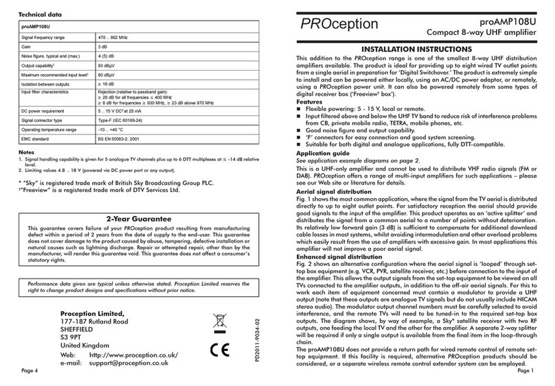
Fig.1 proMHD14R  aerial a plifier installation
showing two (optional) ethods for splitting outputs.
Fig.2 proMHD14R  return path application with Sky* box.
Note: dish and SCART connections o itted for clarity.
Fig.3 cable tie fixing Fig.4 fixing to flat surface
Fig.5 Fixing the amplifier
module directly (indoor
application only, discard
mouldings). Earth terminal
(see text).
pro HD14R
VCR
(optional)
Sky* Digibox
or Sky+ box
Outlets
proOUT11C
PROception
IN
ANT IN
RF OUT-2 RF OUT-1
RF OUT
ANT IN
proSAT1EYE
Power unit
proPSU12F
pro HD14R
proSPL204
splitter
IN
Outlets proOUT11C
PROception
PROception
IN

Other PROception Amplifier manuals

PROception PROAMP24 User manual

PROception

PROception PROAMP24 User manual

PROception proAMP108U User manual

PROception

PROception proAMP108U User manual

PROception proAMP11 User manual

PROception

PROception proAMP11 User manual

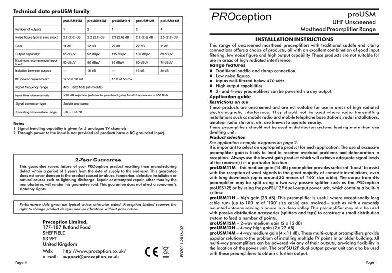
PROception proUSM Series User manual

PROception

PROception proUSM Series User manual

PROception proAMP11 User manual

PROception

PROception proAMP11 User manual

PROception proAMP24 User manual

PROception

PROception proAMP24 User manual

PROception PROAMP310X User manual

PROception

PROception PROAMP310X User manual

PROception proAMP24 Mk 3 User manual

PROception

PROception proAMP24 Mk 3 User manual

PROception proAMP310X User manual

PROception

PROception proAMP310X User manual

PROception PROAMP11 User manual

PROception

PROception PROAMP11 User manual

PROception proTLA41 User manual

PROception

PROception proTLA41 User manual

Popular Amplifier manuals by other brands

Audionet PRE I G2 owner's manual

Audionet

Audionet PRE I G2 owner's manual

ELETTROMEDIA HERTZ HMD8 DSP user manual

ELETTROMEDIA

ELETTROMEDIA HERTZ HMD8 DSP user manual

Bryston C Series B60R Exterior dimensions

Bryston

Bryston C Series B60R Exterior dimensions

ITC T-10AP Operation manual

ITC

ITC T-10AP Operation manual

Toa P-150D Operating instructions manual

Toa

Toa P-150D Operating instructions manual

Pioneer PRS-D4200F - Premier Amplifier owner's manual

Pioneer

Pioneer PRS-D4200F - Premier Amplifier owner's manual

Cary Audio Design CINEMA 6 owner's manual

Cary Audio Design

Cary Audio Design CINEMA 6 owner's manual

axing BVS 14-69 Operation instructions

axing

axing BVS 14-69 Operation instructions

Yamaha WXA-50 owner's manual

Yamaha

Yamaha WXA-50 owner's manual

Kenwood MA-5100 instruction manual

Kenwood

Kenwood MA-5100 instruction manual

Sonic Frontiers Sonic Frontiers SFM-160 PRIVATE operating manual

Sonic Frontiers

Sonic Frontiers Sonic Frontiers SFM-160 PRIVATE operating manual

Snell Power Amplifier SPA 200 Specification sheet

Snell

Snell Power Amplifier SPA 200 Specification sheet

ButtKicker BKA1000-P owner's manual

ButtKicker

ButtKicker BKA1000-P owner's manual

AEM LSA150-001 Installation and operation manual supplement

AEM

AEM LSA150-001 Installation and operation manual supplement

AudioSource Pre One/A owner's manual

AudioSource

AudioSource Pre One/A owner's manual

Kenwood KA-770D instruction manual

Kenwood

Kenwood KA-770D instruction manual

Antelope MP32 user manual

Antelope

Antelope MP32 user manual

Peavey PV 3800 operating manual

Peavey

Peavey PV 3800 operating manual

manuals.online logo
manuals.online logoBrands
  • About & Mission
  • Contact us
  • Privacy Policy
  • Terms and Conditions

Copyright 2025 Manuals.Online. All Rights Reserved.