manuals.online logo
Brands
  1. Home
  2. •
  3. Brands
  4. •
  5. PROception
  6. •
  7. Amplifier
  8. •
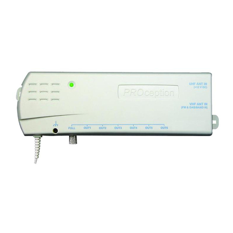
  9. PROception proUSM Series User manual

PROception proUSM Series User manual

Page 1Page 4
PD2011-9016-02
PROception
Proception Limited,
177-187 Rutland Road
SHEFFIELD
S3 9PT
United Kingdom
eb: http://www.proception.co.uk/
e-mail: [email protected]
Performance data given are typical unless otherwise stated. Proception Limited reserves the
right to change product designs and specifications without prior notice.
proUSM
UHF Unscreened
Masthead Preamplifier Range
2-Year Guarantee
This guarantee covers failure of your PROception product resulting from manufacturing
defect ithin a period of 2 years from the date of supply to the end-user. This guarantee
does not cover damage to the product caused by abuse, tampering, defective installation or
natural causes such as lightning discharge. Repair or attempted repair, other than by the
manufacturer, ill render this guarantee void. This guarantee does not affect a consumers
statutory rights.
INSTALLATION INSTRUCTIONS
This range of unscreened masthead preamplifiers with traditional saddle and clamp
connections offers a choice of products, all with an excellent combination of good input
filtering, low noise figure and high output capability. These products are not suitable for
use in areas of high radiated interference.
Range features
nTraditional saddle and clamp connection.
nLow noise figures.
nInputs well-filtered below 47 MHz.
nHigh output capabilities.
n2- and 4-way preamplifiers can be powered via any output.
Application guide
Restrictions on use
These products are unscreened and are not suitable for use in areas of high radiated
electromagnetic interference. They should not be used where radio transmitting
installations such as mobile radio and mobile telephone base stations, radar installations,
amateur radio stations, etc. are known to operate nearby.
These preamplifiers should not be used in distribution systems feeding more than one
dwelling unit.
Product selection
See application example diagrams on page 2.
It is important to select an appropriate product for each application. The use of excessive
preamplifier gain is likely to lead to receiver overload problems and deterioration in
reception. Always use the lowest gain product which will achieve adequate signal levels
at the receiver(s) in a particular location.
proUSM11M  this medium gain (14 dB) preamplifier provides sufficient boost to assist
with the reception of weak signals in the great majority of domestic installations, even
with long downleads (up to around 3 metres of 1  size cable). The output from this
preamplifier may be split using a two-way passive splitter such as the PROception
proUSS12P, or by using the proPSU12F dual-output power unit, which contains a built-in
splitter.
proUSM11H  high gain (25 dB). This preamplifier is useful where exceptionally long
cable runs (up to 1 m of 1  size cable) are involved  such as with a remotely
mounted antenna serving a house in a deep valley. This preamplifier may also be used
with passive distribution accessories (splitters and taps) to construct a small distribution
system to feed a number of points.
proUSM12M  2-way medium gain (2 x 12 dB)
proUSM12H  4-way high gain (2 x 22 dB)
proUSM14M  4-way medium gain (4 x 11 dB). These multi-output preamplifiers provide
popular solutions to the problem of installing multiple TV points in an older building. All
multi-way preamplifiers can be powered via any of their outputs, providing flexibility in
the location of the power unit. The proPSU12F dual-output power unit can also be used
with these preamplifiers to obtain a further output.
Notes
1. Signal handling capability is given for 5 analogue TV channels.
2. Through-po er to the input is not provided (all products have a DC grounded input).
Technical data proUSM family
M11MSUorpM21MSUorpH11MSUorpH21MSUorpM41MSUorp
stuptuoforebmuN12124
).xamdna(lacipyterugifesioNBd)6.2(2.2Bd)8.2(2.2B
d)6.2(3.2Bd)8.2(2.2Bd)8.2(.2
niaGBd41Bd21Bd2Bd22Bd11
¹ytilibapactuptuOVµBd9VµBd29VµBd01VµBd201VµBd98
tupnidednem
mocermumixaM
¹level VµBd08VµBd08VµBd08VµBd08VµBd87
stuptuoneewtebnoitalosIBd61 Bd61Bd03
²tnemeriuqerrewopCDAm02taV
21Am0taV21
egnarycneuqerflangiS)sledomlla(zHM268..074
citsiretcarahcretliftupnI ³seicneuqerfllarof)niagdn
abssapotevitaler(noitcejerBd02 [4zHM00
epytrotcennoclangiSpmalcdnaelddaS
egnarerutarepmetgnitarepOC°04+..0
1-
Power unit
proPSU11C
or
proPSU11F
outlet
proOUT11C
OUT IN
proUSM11M
or
proUSM11H
Page 3Page 2
Powering and power units
All preamplifiers require a 12 volt DC power supply and are compatible with the
proPSU11C proPSU11F and proPSU12F power units. They may also be powered from
PROception multi-way preamplifiers types proAMP24 proAMP26 and proAMP28. The
multi-way versions proUSM12M proUSM12H and proUSM14M may be powered via
any of their outputs.
Signal connections
All connections must be made with a good quality coaxial cable such as cable
benchmarked under the CAI scheme. Cheap cables with poor braid coverage should be
avoided as should cables with aluminised plastic foil screens since it is difficult to make
reliable connections to these.
Recommended cable preparation details are shown in Fig. 6 for cables with and without a
foil screen.
Location and mounting
In general the aerial and preamplifier should be mounted in a clear high position with a
good view toward the TV transmitter. The preamplifier location should be chosen to
minimise the risk of interference; e.g. avoid having the aerial preamplifier or cabling
close to power and telephone lines.
For best noise performance the input cable from the aerial to the preamplifier should be
kept as short as practicable but do not install the preamplifier amongst the elements of
an aerial. With a centre-mounted aerial the preamplifier should be mounted on the
mast at least one metre below the closest part of the aerial. With a rear-mounted aerial
the preamplifier may be positioned behind the aerials reflector provided this is of the
grid or mesh type.
Methods for mounting the preamplifier are illustrated in Figures 4 and 5. The cable tie
fixing is intended to support the weight of the preamplifier only. Cables should be taped
to the mast at intervals of approximately 400 mm to ensure that their weight is adequately
supported.
proUSM11H
Power unit
proPSU12F
proUSM14M
Outlets proOUT11C
proUSS12 splitter*
IN *proUSS12P
if installed on
powered leg
Power unit
proPSU11F
OUT
IN
Outlets proOUT11C
*Tap *Tap
5 ohm
termination
*NB choose tap values to give
approximately dB gain from
antenna to outlet plates, allowing
for cable losses.
Fig. 1  Basic masthead amplifier installation
Fig. 2  proUSM11 in a simple distribution system
Fig. 3  Example multi-way installation showing alternative ways of splitting outputs.
Fig. 4  cable tie fixing Fig. 5  fixing to flat surface
When connecting the cables take care to tighten all connections taking particular care
with the braid clamps which should be as tight as possible without crushing the cable.
The importance of achieving sound braid connections cannot be over-stressed. Ensure
that the sliding cover is firmly closed once connection is complete.
OUTIN
OUTIN
IN OUTINOUT
Fig. 6  Recommended cable stripping details
For cables with
foil screen
6 mm
6 mm
6 mm
4 mm
For cables
without
foil screen

This manual suits for next models

5

Other PROception Amplifier manuals

PROception proAMP310X User manual

PROception

PROception proAMP310X User manual

PROception PROAMP11 User manual

PROception

PROception PROAMP11 User manual

PROception proAMP24 Mk 3 User manual

PROception

PROception proAMP24 Mk 3 User manual

PROception proAMP11 User manual

PROception

PROception proAMP11 User manual

PROception proAMP24 User manual

PROception

PROception proAMP24 User manual

PROception proTLA41 User manual

PROception

PROception proTLA41 User manual

PROception proAMP108U User manual

PROception

PROception proAMP108U User manual

PROception proMHD14R Operation and maintenance manual

PROception

PROception proMHD14R Operation and maintenance manual

PROception PROAMP310X User manual

PROception

PROception PROAMP310X User manual

PROception PROAMP24 User manual

PROception

PROception PROAMP24 User manual

PROception proAMP11 User manual

PROception

PROception proAMP11 User manual

Popular Amplifier manuals by other brands

Harman Kardon HK6100 Technical manual

Harman Kardon

Harman Kardon HK6100 Technical manual

Behringer BASS V-AMP LX1B user manual

Behringer

Behringer BASS V-AMP LX1B user manual

Engl Road operating manual

Engl

Engl Road operating manual

Marshall Amplification MG2FX owner's manual

Marshall Amplification

Marshall Amplification MG2FX owner's manual

Fiberplex VIS-1832 user manual

Fiberplex

Fiberplex VIS-1832 user manual

AR 125W1000A Operating and service manual

AR

AR 125W1000A Operating and service manual

Yamaha DSP-A595a Service manual

Yamaha

Yamaha DSP-A595a Service manual

Gisen Audio MM Series Operation manual

Gisen Audio

Gisen Audio MM Series Operation manual

Befaco i4 user manual

Befaco

Befaco i4 user manual

Orion HCCA3000.1D-SPLX manual

Orion

Orion HCCA3000.1D-SPLX manual

Gryphon Ampli-Phone Instructions for use

Gryphon

Gryphon Ampli-Phone Instructions for use

A SYSTEMS SR707 user manual

A SYSTEMS

A SYSTEMS SR707 user manual

Profile California 400MSX Installation and owner's manual

Profile

Profile California 400MSX Installation and owner's manual

GAI-Tronics 751-005 Quick manual

GAI-Tronics

GAI-Tronics 751-005 Quick manual

Pioneer GM-X352 - Amplifier Service manual

Pioneer

Pioneer GM-X352 - Amplifier Service manual

AUDIO TELEX SA120-4 operating instructions

AUDIO TELEX

AUDIO TELEX SA120-4 operating instructions

CARVIN R1000 HEAD operating manual

CARVIN

CARVIN R1000 HEAD operating manual

Rotel RTC-940AX owner's manual

Rotel

Rotel RTC-940AX owner's manual

manuals.online logo
manuals.online logoBrands
  • About & Mission
  • Contact us
  • Privacy Policy
  • Terms and Conditions

Copyright 2025 Manuals.Online. All Rights Reserved.