PROception proAMP310X User manual

INSTALLATION INSTRUCTIONS
This versatile product is an addition to the PROception range of multi-way distribution
amplifiers. The unit has two modes of operation, allowing it to be used either as a
straightforward 10-way aerial amplifier for off-air signal distribution, or as a return-
path amplifier with its HF input fed from the second loop-through output (RF O T-
2) of a Sky* satellite receiver or PVR. In its return-path mode full support is provided
for remote infrared receivers (eyes). The use of F connectors makes the amplifier
easy to install and helps to ensure good system screening.
Features
nSeparate filtered inputs for the FM radio, DAB (Band III) and HF TV frequency
bands.
nTen independent outputs.
nDual-mode operation plain signal distribution amplifier, or return-path amplifier.
nFlexible powering options local or remote power supply location.
nAutomatic mode selection with 2-colour LED mode and power indicator.
nBandpass filters on VHF inputs. HF input filtered below 470 MHz to reduce risk
of interference from CB, private mobile radio, TETRA, etc.
nLine-power for preamplifier available at HF input.
nSuitable for both digital and analogue applications, fully DTT-compatible.
Mode 1 application guide
See Figs. 1(a) & 1(b). Mode 1 (green LED) is also known as aerial amplifier mode.
In Mode 1 the unit functions as a straightforward multi-way amplifier for distribution
of off-air and/or locally generated RF signals around a building. The input signals
will usually come directly from the corresponding aerials. Line-power (5 V) for a
masthead or similar preamplifier is available at the HF input in this mode.
Line-power for this amplifier (12 15 V DC) can be supplied via any of the ten
outputs. Alternatively, if a mains supply is available near the amplifier, a suitable
local AC/DC mains power adaptor may be used instead of line-powering.
In Mode 1 no power is passed to unpowered outputs and the return-path amplifier
and remote control functions are completely disabled.
Fig.1(a) shows a typical Mode 1 application with power provided by a proPS 112X
power unit connected in one of the output lines.
Fig. 1(b) shows a similar installation to Fig.1(a), except that a proMHD11L
masthead preamplifier is used to boost the HF input signals and power is provided
by an AC/DC power adaptor adjacent to the amplifier. This diagram also shows how
one or more of the output lines can be split to provide additional outlet points.
Page 1Page 8
PD2011-9031-02
proAMP310X
Dual-mode 3-band
10-way Amplifier
Proception Limited,
177-187 Rutland Road
SHEFFIELD
S3 9PT
United Kingdom
eb: http://www.proception.co.uk/
e-mail: [email protected]
PROception
* Sky and Sky+ are registered trade marks of British Sky Broadcasting Group PLC.
reeview is a registered trade mark of DTV Services Ltd.
Notes
1. UHF signal handling capability is given for 5 analogue TV channels plus up to 6 DTT ultiplexes at £ -14 dB
relative level.
2. The first (higher) figure is for analogue signals and the second (lower) is for digital (16- or 64-QAM).
3. Rejection figures are given relative to the no inal passband gain.
4. Absolute ini u voltage, easured to the botto of the ripple present.
5. Highest reco ended ean voltage for operation over the full te perature range.
6. Eye load should be restricted to 80 A or less when using proPSU112X power unit (see text).
7. Both UHF prea p and IR eye power outputs have fold-back short-circuit protection, but not overload
protection. It is the installers responsibility to ensure that the stated current ratings are not exceeded.
Certain features of this amplifier are the subject of UK patent application GB 2425443.
Performance data given are typical unless otherwise stated. Proception Limited reserves the right to
change product designs and specifications without prior notice.
2-Year Guarantee
This guarantee covers failure of your Proception product resulting from a manufacturing defect
within a period of two years from the date of supply to the end-user.
This guarantee does not cover damage to the product cause by abuse, tampering, defective
installation or natural causes such as lightening discharge. Repair or attempted repair, other
than by the manufacturer, will render this guarantee void.
This guarantee does not affect a consumers statutory rights.
Technical data proAMP310X
scitsiretcarahcFR tupniTNAMFtupniTNABADtupniFHU
egnarycneuqerflangiSzHM801..5.78zHM032..5.012zHM268..074
niag
drawroFd5.1d4d5.4
niaghtapnruteR )ylno2edoM(d3
).xam(dnalacipyt,erugifesioNd)7(4d)5(5.3d)4(5.2
ytilibapac
tuptuOVµd28
1
tupnidednemmoceR
slevellangis
mumixamVµd07Vµd07Vµd36/87
2
muminimVµd05Vµd03Vµd34/85
2
stuptuoneewtebnoitalosI ³d03 ³d72 ³d42
noitcejerretliftupnI
3
seicneuqerfehtrof )f( detats
³d81
f£,zHM27 f³zHM051
³d22
f£,zHM541 f³zHM503
³d62
f£zHM004
stnemeriuqerrewoP1edoM2edoM
stimilegatlov:rewopCD5.8
4
81..
5
V5.01
4
81..
5
V
gnidaoltnerruC
ylnoreifilpmaAm08Am021
metsyslluf)daolreifilpmaerpAm03.lcni(Am011 daol'eye'latotAm001.lcni(
Am022
6
)
stuptuorewoplanretxE
7
.xamAm03ta.xorppaV5:pmaerpFHU )01x(.xamAm01ta.xorppaV9:'eye'RI
scitsiretcarahclarene
epytrotcennoclangiS)42-96106CEI(F-epyT
egnarerutarepmetgnitarepOC°04+..01-
dradnats
CME1002:2-38005NES

287
287
287
287
287
287
287
287 287 287
8+)
,1 '$%
$17
,1
)0
$17
,1
SUR$03;
PROception
32:(5
02'(
32:(5
9
287
287
287
287
287
287
287
287 287 287
8+)
,1 '$%
$17
,1
)0
$17
,1
SUR$03;
PROception
32:(5
02'(
32:(5
9
Installation signal connections
To preserve RF screening integrity the signal connections to the amplifier should be
made using good quality coaxial cable and connectors. This is particularly important
with DTT to minimise the ingress of impulsive electrical interference. The use of cable
benchmar ed under the CAI scheme is recommended.
Crimp F connectors, used in accordance with the manufacturers instructions, will
give the best results. The importance of achieving sound braid connections cannot be
over-stressed. Connectors should be tightened with a spanner, not left finger-tight.
Unused inputs and outputs of this amplifier do not need to be terminated.
Installation mains power supply
Any fixed wiring installed to supply power for this amplifier should comply with BS 7671
(IEE wiring regulations) and, where relevant, Part P of the building regulations. Refer
to the instructions provided with the power supply unit for other safety information.
Installation system equipotential bonding
A bonding terminal is provided on the amplifier for use where necessary.
Distribution systems supplying signals to more than one household should comply
with the safety requirements of BS EN 60728-11. This effectively requires earthed
equipotential bonding of the system. The use of isolated outlet plates is no longer
recommended since they compromise screening integrity and allow ingress of
interference.
Advanced configuration features
Note: access to the features described in this section involves opening the unit. The procedures
below should only be carried out by a competent person, preferably under workshop conditions.
UHF input line-power (preamplifier power : where equipment (such as an
attenuator) connected to the UHF input might be damaged by the presence of the
5V output, or may cause the 30 mA current rating to be exceeded, the input line-
power can be permanently disabled by removing the internal LINE-POWER jumper.
Forced Mode 2 operation: where Mode 2 operation is desired, but it is impracticable
to connect a S y receiver directly to the UHF input to provide a 9 V sense voltage, the
unit can be forced into Mode 2 by placing a jumper lin on the 2-pin header labelled
FORCE MODE 2. Since UHF input line-power will not usually be required in Mode 2,
the existing LINE-POWER jumper can simply be moved to the FORCE MODE 2 header
position. Forced Mode 2 operation is only relevant when a local power unit is in use,
connected to the DC power port.
Access: to open the unit remove the four corner screws from the rear cover. Separate
the two halves of the moulded cover and withdraw the screened amplifier assembly,
together with the attached DC port connector. Remove the top metal lid this is the
side with the LED. One side of the PCB is now exposed. Ta e great care not to disturb
any of the coils, as this could de-tune the input filters. The LINE-POWER jumper is
located just above the LED; the Force MODE 2 jumper is in the bottom right-hand
corner of the board, near the equipotential bonding terminal.
Re-assembly: when reassembling the unit ta e care to ensure that the LED does not
become trapped and pushed inside the unit, and that the DC port connector is correctly
seated in the cover mouldings before replacing the screws.
Page 7Page 2
Fig. 1 (a) example Mode 1 application with remote power unit.
Fig 1. (b) example mode 1 application with local power unit and showing optional use of
UHF preamplifier and output splitter.
Outlets
proOUT11C (single)
or proOUT12C (dual)
FM and/or
DA receiver
UHF aerial DA aerial
FM aerial
proPSU112X
power unit
Freeview box
Freeview box
Equipotential bonding
(see text, p 7)
Outlets
proOUT11C (single)
or proOUT12C (dual)
FM and/or
DA receiver
UHF aerial DA aerial FM aerial
Freeview box Freeview
box
Equipotential bonding
(see text, p7)
proSPL204
splitter
proMHD11L
preamplifier
proPSA123
AC/DC mains
power adaptor

Page 3
Mode 1 powering options
Power for operation in Mode 1 can be supplied by either of the following options:
na PROception proPSU112X 12 V power unit connected anywhere in any of the
output lines Fig 1(a);
na local AC/DC mains power adaptor such as the PROception proPSA123 connected
to the DC power port Fig 1(b) The adaptor need not be regulated and needs
to have a standard 2 1 mm DC connector with the correct polarity (centre pin
+ve) If a 3rd party adaptor is to be used its output should conform to the
requirements given in the technical data section (page 8)
Note: this amplifier is not suitable for powering from the aerial sockets of DVB-T (DTT
or Freeview) receivers The voltage and current available from such receivers (usually
5V at 30mA) are insufficient
Mode 1 preamplifier option (preamplifier power)
Line-power for a masthead or similar preamplifier is available at the UHF input in
Mode1 The amplifier provides approximately 5V with a current rating of 30mA
max , suitable for powering a PROception proMHD11L or proMHD11M preamplifier
If using other amplifiers take care to ensure that the current rating is not exceeded
Use a preamplifier only when the UHF input signals would otherwise be too low in
level i e where the signal levels from the aerial are low, or where there is an
unusually long cable run between the aerial and the proAMP310X amplifier Always
use the minimum amount of preamplifier gain necessary to obtain satisfactory signal
levels at the amplifier input
Preamplifier power is normally present at the UHF input, but will shut down if the
aerial presents a short-circuit at the input Note that this shut-down is not self-resetting
If preamplifier power is wanted, but has been shut-down by a temporary short circuit,
it must be reset manually by removing power to the amplifier for a few seconds
If necessary, preamplifier power can be permanently disabled by means of an internal
jumper (see Advanced configuration features on page 7)
Mode 1 additional UHF sources
Any additional UHF signal sources such as CCTV camera channels should be combined
with the aerial signal feed ahead of the proAMP310X This is best done using
equipment providing a buffered loop-through arrangement (e g the PROception
proMOD1Mk2 video and audio modulator) or by the use of suitable combining
filters The practice of using wideband combiners is discouraged since it can degrade
signal-to-noise ratios and can cause locally generated signals to be radiated from
the aerial, possibly causing interference to other viewers
Note: where auxiliary equipment connected to the UHF input might be affected or
damaged by the 5V preamplifier power, the latter should be disabled using the
jumper facility mentioned in the previous section
Mode 2 eye count
When using the remote powering option with the proPSU112X the total number of
infrared eyes on the system may need to be restricted The proPSU112X is rated to
supply a maximum of 200mA, and approximately 120mA is drawn by the amplifier
itself Thus the total eye load is limited to 80mA This means that a maximum of
eight industry-standard eyes (each consuming about 10mA) may be connected to
the amplifier outputs This restriction is removed if the PROception proSAT1EYEMk2
eye is used, since this consumes less than 5mA
Up to 10 eyes may be connected without restriction when using the proPSA123 AC/ DC
mains power adaptor
plitting outputs
As with any multi-way amplifier the output signals can be split as illustrated in
Fig 1(b) to provide additional outlet points The PROception proSPL204 splitter is
suitable for this in Mode 1 and introduces approximately 4dB insertion loss
Splitting outputs in Mode 2 is not recommended, since it is not possible to provide
individually protected eye power to the split outputs
ignal levels
This amplifier has relatively low forward gain figures and assumes that adequate
input signal levels will be available from properly installed aerials The amplifier
gains are sufficient to compensate for additional distribution cable losses in a typical
domestic-scale system whilst avoiding the intermodulation and other overload
problems which result from the use of excessive gain
Recommended minimum and maximum signal levels for each of the frequency bands
are given in the Technical data section on page 8 Particular attention should be paid
to the input VHF radio signal levels In city areas very strong signals are often received
and it may be necessary to use attenuators on one or both of the VHF inputs to avoid
overloading the amplifier
Outlet plates
The use of outlet plates is recommended to provide a professional standard of finish
to the distribution system PROception screened outlet plates are recommended for
use with this amplifier The diplexed TV and radio plate (proOUT12C) allows both TV
and radio equipment to be connected simultaneously to an outlet point Single outlets
(proOUT11C) may also be used and will allow either TV or radio equipment to be
used The system diagrams in Figs 1&2 show both types of plate in use
In Mode 2 a proOUT11C plate may also be used to provide the UHF return input
connection from the Sky receiver, as illustrated in the diagrams in Fig 2
Installation location and fixing
Choose a location for the amplifier which is dry and not subject to prolonged ambient
temperature conditions of less than -10 °C of more than + 40 °C Fix the unit to a
sound vertical surface such as a wall or equipment mounting board Ventilation gaps
of at least 50 mm should be left around the front and all sides of the unit More
clearance will be required around sides where cables are connected
Do not install the amplifier or its associated power unit where they may
become smothered with curtains or other soft furnishing fabrics. When
installing the amplifier and power unit in a roof space ensure that they will
not come into contact with thermal insulation material.
Page 6

287
287
287
287
287
287
287
287 287 287
8+)
,1 '$%
$17
,1
)0
$17
,1
SUR$03;
PROception
32:(5
02'(
32:(5
9
PROception
TV
IN
proSAT1EYE
Mk 2
Mode 2 application guide
See Figs. 2(a) & 2(b). Mode 2 (orange LED) is also known as return-path mode.
In Mode 2 the unit functions as a return-path amplifier. This mode is appropriate
where the UHF input to the amplifier is provided from the second loop-through
output (RF UT-2) of a Sky satellite receiver or PVR. A return RF path is enabled in the
proAMP310X, allowing remote infrared receiver eyes such as the PROception
proSAT1EYEMk2 to communicate with the Sky box. This provides remote control
extension so that the Sky receiver can be controlled from a remote viewing location.
Mode 2 is automatically enabled when the amplifier detects the presence of 9V (or
higher) DC at its UHF input (see the following section for further details). In this mode
the LED indictor changes from green to orange and a voltage (approx. 9V DC) is
present at each output for powering a remote infrared receiver. Infrared receiver
power is individually short-circuit protected, so that a DC short at any output will not
affect operation of remote control via other outputs.
Fig.2(a) shows a typical Mode 2 application with power provided by a proPSU112X
power unit connected in the UHF return feed from the Sky receiver.
Fig.2(b) shows a similar installation to Fig.2(a), except that power is provided by
an AC/DC mains power adaptor adjacent to the amplifier.
Mode 2 powering options
Power and sensing voltages for operation in Mode 2 can be supplied by either of the
following options:
na PROception proPSU112X 12 V power unit connected anywhere in the UHF return
feed (i.e. in the line between RF UT-2 of the Sky receiver and the amplifiers
UHF input) Fig.2(a);
na local AC/DC mains power adaptor such as the PROception proPSA123 connected
to the DC power port Fig.2(b). The adaptor need not be regulated and needs
to have a standard 2.1 mm DC connector with the correct polarity (centre pin
+ve). If a 3rd party adaptor is to be used its output should conform to the
requirements given in the technical data section (page 8). When using this option
the UHF input must be directly connected to the Sky receiver RF UT-2 since the
9V second outlet power needs to be sensed at the UHF input to switch the
amplifier to Mode 2. The current drawn from the Sky receiver in this configuration
is very small (typically 3 5mA).
The Sky receiver should be configured in its INSTALLER SET-UP menu to provide
power on RF UT-2. n the Sky handset press SERVICES, 4, 0, 1, SELECT, then select
the SEC ND UTLET P WER SUPPLY option. Set this to be N (the default state is
FF), SAVE SETTINGS and BACK UP out of the menu.
Interlock function: if a connector is present in the amplifiers local DC power port
then power will not be accepted via the UHF input, regardless of whether the AC/DC
mains power adaptor is actually providing power. This is an interlock function which
prevents the Sky receiver trying to power the entire distribution system in the event of
failure of, or loss or power to, the local power adaptor.
Important note: this amplifier is not suitable for powering directly from a
Sky receiver. he configuration where the Sky receivers RFOU -2 is directly
connected to the amplifiers UHF input without a local mains power adaptor
present is not permitted.
Page 4 Page 5
Fig. 2 (a) example Mode 2 application with remote power unit.
Fig. 2 (b) example Mode 2 application with local power unit.
Outlets
proOUT11C (single)
or proOUT12C (dual)
FM and/or
DA receiver
UHF aerial DA aerial
FM aerial
proSAT1EYE IR receiver
Equipotential bonding
(see text, p7)
proPSA123
AC/DC mains
power adaptor
VCR etc.
(optional)
Sky* or
Sky+*
RF
OUT-2
RF
OUT-1
ANT IN
Freeview
box
Return inlet
proOUT11C
(Note: SCART leads and dish connections omitted for clarity)
Outlets
proOUT11C (single)
or proOUT12C (dual)
FM and/or
DA receiver
UHF aerial DA aerial
FM aerial
proSAT1EYE IR receiver
Equipotential
bonding
(see text, p 7)
VCR etc.
(optional)
Sky* or
Sky+*
RF
OUT-2
RF OUT-1
ANT IN
Freeview
box
Return inlet
proOUT11C
proPSU112X
power unit
(Note: SCART leads and dish connections omitted for clarity)
287
287
287
287
287
287
287
287 287 287
8+)
,1 '$%
$17
,1
)0
$17
,1
SUR$03;
PROception
32:(5
02'(
32:(5
9
PROception
TV
IN
proSAT1EYE
Mk 2
Other PROception Amplifier manuals
PROception
PROception proTLA41 User manual
PROception
PROception proMHD14R Operation and maintenance manual
PROception
PROception PROAMP11 User manual
PROception
PROception PROAMP24 User manual

PROception
PROception proAMP11 User manual
PROception
PROception proAMP24 Mk 3 User manual
PROception
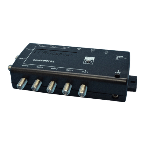
PROception PROAMP310X User manual

PROception
PROception proAMP11 User manual

PROception
PROception proAMP24 User manual
PROception
PROception proUSM Series User manual
