manuals.online logo
Brands
  1. Home
  2. •
  3. Brands
  4. •
  5. PROception
  6. •
  7. Amplifier
  8. •
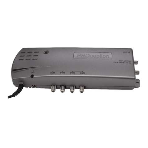
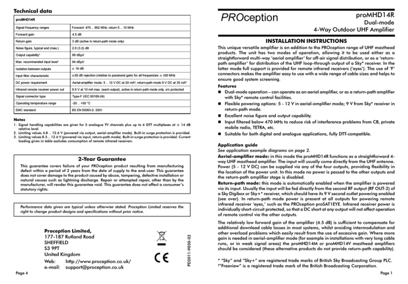
  9. PROception proAMP11 User manual

PROception proAMP11 User manual

Safety Instructions
Page 1Page 4
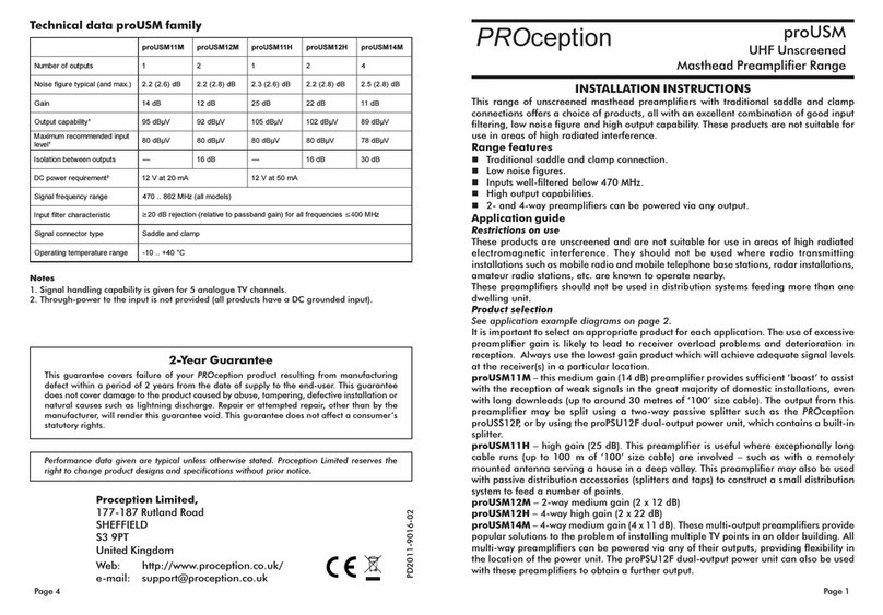
VHF-UHF Amplifiers
PD2011-9002-04
INSTALLATION INSTRUCTIONS
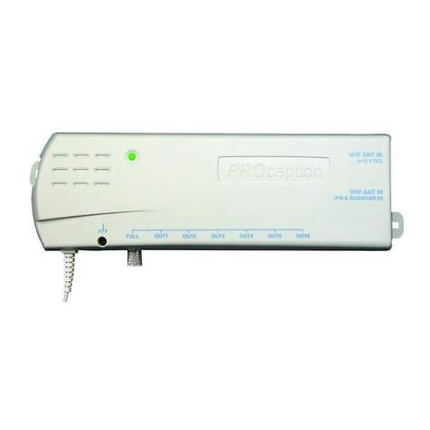
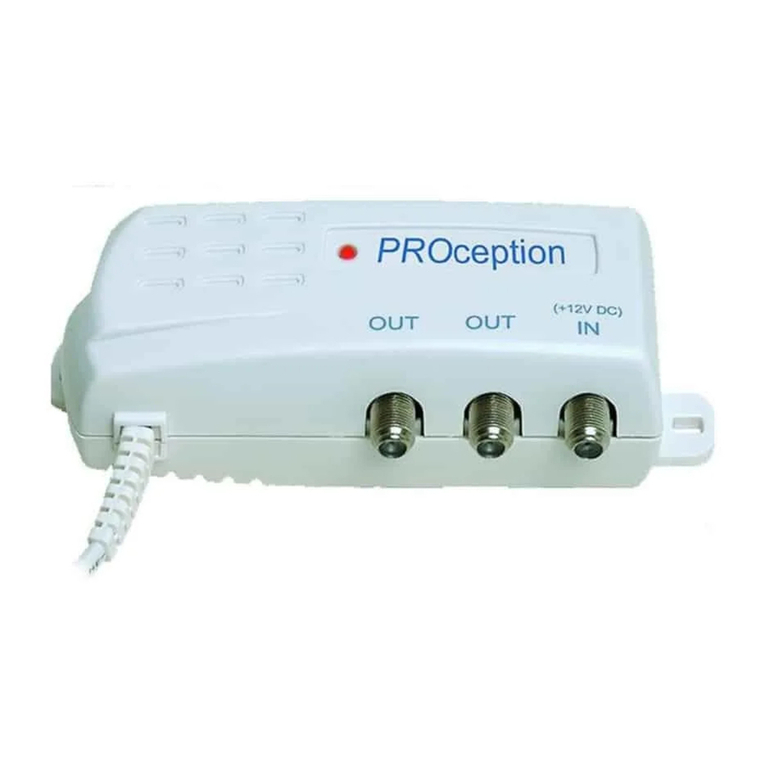
These general-purpose amplifiers have a wide range of uses in small domestic reception
and distribution systems. The proAMP11 and proAMP12 are traditional 1- and 2-way
aerial signal amplifiers. proAMP12 is a 2-way amplifier with a 7 MHz return path, for use
with infrared remote control extender systems of the type which connect to the F OUT-2
output of a Sky* Digibox.
Features
nFrequency range 88  862 MHz (proAMP11 & proAMP12) or 470  862 MHz
(proAMP12 ).
nOne-way signal booster / line-extender amplifier (proAMP11).
nTwo-way aerial distribution amplifier (proAMP12).
nTwo-way return path distribution amplifier for Sky* I remote control (proAMP12 ).
nVery high output capability.
nBuilt-in power for two I eyes (proAMP12 ).
Fixing
Fix the amplifier to a sound vertical surface such as a wall, skirting board or equipment
mounting board. Ventilation gaps of at least 50 mm should be left around the front and all
sides of the unit. More clearance will be required below the unit to allow access for the
signal cables.
Do not leave the amplifier resting on a carpet or install it where it may become
smothered with curtains or other soft furnishing fabrics. When installing the
amplifier unit in a roof space ensure that it will not come into contact with thermal
insulation material.
Signal connections
To preserve F screening integrity the signal connections to the amplifier should be made
using good quality coaxial cable and connectors. This is particularly important with digital
terrestrial TV (DTT) to minimise the ingress of impulsive electrical interference from home
appliances.
nThe use of cable benchmarked under the CAI scheme is recommended.
nAmplifiers proAMP11 and proAMP12 require IEC connectors (IEC 60169-2).
nAmplifier proAMP12 requires Type-F connectors (IEC 60169-24).
For both connector types the use of crimp connectors, used in accordance with the
manufacturers instructions will give the best results. The importance of achieving sound
braid connections cannot be over-stressed. F connectors should be tightened with a
spanner, not left finger tight.
Proception Limited,
177-187 Rutland Road
SHEFFIELD
S3 9PT
United Kingdom
eb: http://www.proception.co.uk/
e-mail: [email protected]
Performance data given are typical unless otherwise stated. Proception Limited reserves the right to
change product designs and specifications without prior notice.
proAMP11
proAMP12
proAMP12R
2-Year Guarantee
This guarantee covers failure of your PROception product resulting from manufacturing defect
within a period of 2 years from the date of supply to the end-user This guarantee does not
cover damage to the product caused by abuse, tampering, defective installation or natural
causes such as lightning discharge Repair or attempted repair, other than by the manufacturer,
will render this guarantee void This guarantee does not affect a consumers statutory rights
* Sky is a registered trademark of British Sky Broadcasting Group PLC.
OVERHEATING
These amplifiers are intended for use in moderate climates only They should not be used in
tropical regions The recommended ventilation clearances and other precautions given in the
relevant section of this instruction leaflet should be observed to prevent overheating No unit
should be fixed where it is likely to become smothered by soft furnishing fabrics such as curtains,
or by thermal insulation material in a roof space or building void Mains powered equipment
should not be left resting on a carpet
WATER AND FIRE RISKS
The appliance is not waterproof It is intended for indoor use only and must not be fixed where
it could be exposed to dripping or splashing water Objects containing liquids should not be
placed on or near the appliance To prevent risk of fire, no object with a naked flame should be
placed on or near the appliance, or its associated wiring
MAINS PLUG AND DISCONNECTION FROM THE SUPPLY
The appliance is supplied with a standard fused plug fitted If this is unsuitable, refer to the
instructions below If you need to change the fuse in the fitted plug, a 3 Amp fuse to BS 1362
carrying the ASTA or BSI approval mark must be used Always replace the plastic fuse carrier
when renewing the fuse The plug (or other means of disconnection from the supply, if used)
should remain readily accessible for operation when necessary The LED power indicator on
this equipment should not be regarded as providing reliable indication of supply disconnection
CHANGING THE PLUG
If the fitted mains plug is not suitable for the socket-outlets in use, it should be cut off and a
new plug fitted
Wiring the new plug: Instructions supplied with the new plug should be followed The brown
wire must be connected to the live (L) terminal of the plug and the blue wire to the neutral (N)
terminal Neither wire should be connected to the earth (E) terminal of a 3-pin plug (the
appliance does not require an earth connection) Ensure that the cord grip in the plug is correctly
used and clamps the sheath of the cord firmly
Fuse Rating: If the new plug is a fused type, the fuse fitted should be rated at not more than
3 Amp
Caution: The old plug should be destroyed immediately since it would be dangerous if plugged
into a live socket
PROception
Page 3Page 2
Using remote control
The proAMP12R is compatible with the PROception proSAT1EYE and other Sky* remote con
trol extenders. To use the remote control feature it is essential that the amplifier input is fed
directly from the RF OUT 2 connector of the Sky receiver. The amplifier provides 9V DC
power for up to two remote receiver eyes. Note that some Sky receivers require their RF
OUT 2 power option to be enabled in order for remote control extension to work. On the Sky
handset press SERVICES, 4, 0, 1, SELECT, then select the SECOND OUTLET POWER SUPPLY
option. Set this to be ON, SAVE SETTINGS and BACK UP out of the menu.
As always with wired remote extender systems, it is essential to maintain DC continuity through
the coaxial cabling between the amplifier output(s) and the IR receiver equipment in the remote
room(s). For this reason isolated outlet plates cannot be used in the remote rooms and all
connections must be securely clamped, crimped or soldered. When troubleshooting remote
control problems, the first step should be to check for the presence of approximately 9 V DC on
the cable in the remote room.
Mains supply connection and safety notes
The amplifier is supplied with a fitted mains plug and may be plugged directly into a 13 A
(BS 1363) socket outlet. If socket outlets of a different type are in use, please refer to the safety
instructions on page 4. The mains plug should remain readily accessible to permit disconnection
of the unit from the supply. Alternatively the plug may be cut off and the amplifier wired into a
readily accessible fused connection unit, fitted with an approved 3 A fuse to BS 1362. This
method of connection is recommended for permanent distribution system applications, since it
reduces the risk of tampering and accidental disconnection.
If the amplifier is not connected to the mains using the fused plug supplied, or a fused connection
unit, it must be protected by means of a fuse or MCB at the final distribution board of rating not
exceeding 6 A. A readily accessible isolating switch should be provided to allow the unit to be
disconnected from the supply when necessary. Any fixed wiring installed to supply power to this
power unit should comply with BS 7671 (IEE wiring regulations) and, where relevant, Part P of
the building regulations.
The amplifiers are of Class 2 construction and do not require a protective earth connection.
This does not obviate the need to provide a circuit protective (earth) conductor in the supply
wiring, as required by BS 7671.
Distribution systems supplying signals to more than one household should comply with the
safety requirements of BS EN 60728 11. This effectively requires earthed equipotential bonding
of the system. (The use of isolated outlet plates is no longer recommended since they compromise
screening integrity and allow ingress of interference.) Bonding may be effected by using a
PROception proBAR5 equipotential bonding bar.
Fig.1 - Simple distribution system feeding two
TVs from one antenna.
Fig.2 - TV and FM radio distribution
to two rooms.
Fig.3 - VC and Sky* distribution to two rooms
with control of Sky* box.
TV1 TV2
proOUT11C outlets
proOUT12C outlets
proAMP12R
Main TV
Digibox R OUT-1
R OUT-2
(enable power)
VCR
proAMP12
proAMP12
proCOM21VU
FM aerial
Note: SCA T cables have been omitted for clarity.
proSAT1EYE
UHF aerial
UHF aerial
UHF aerial
LNB
Technical data
Note: Output capability is given for 5 analogue TV channels up to 6 DTT multiplexes at -10 dB relative level.
<

11PMAorp21PMAorpR21PMAorp
stuptuoforebmuN122
)dwf(egnarycneuqerflangiSzHM26..5.7 zHM26..5.7 zHM26..074
erugifesioNBd5.2Bd5.3Bd5.3
tuptuo
hcaeotniaGBd21Bd4Bd4
)etonees(ytilibapactuptuOVµBd001VµBd29VµBd29
rewop-enil)'eye'(reviecerRI )detcetorp(Am51ta
V9
epytrotcennoclangiS)2-96106CEI('CEI')2-96106CEI('CEI')42-96106CEI('F'
tnemeriuqerrewopsniaM)AV4(W2tazH05
V032
egnarerutarepmetgnitarepOCº04+..01-
ecnailpmocsdradnatS 1002:2-3005NESB:CME;2002:56006NESB:ytefaS

This manual suits for next models

2

Other PROception Amplifier manuals
PROception proUSM Series User manual

PROception

PROception proUSM Series User manual

PROception proAMP11 User manual

PROception

PROception proAMP11 User manual

PROception proTLA41 User manual

PROception

PROception proTLA41 User manual

PROception PROAMP310X User manual

PROception

PROception PROAMP310X User manual

PROception proAMP108U User manual

PROception

PROception proAMP108U User manual

PROception proMHD14R Operation and maintenance manual

PROception

PROception proMHD14R Operation and maintenance manual

PROception proAMP24 User manual

PROception

PROception proAMP24 User manual

PROception PROAMP11 User manual

PROception

PROception PROAMP11 User manual

PROception PROAMP24 User manual

PROception

PROception PROAMP24 User manual

PROception proAMP310X User manual

PROception

PROception proAMP310X User manual

PROception proAMP24 Mk 3 User manual

PROception

PROception proAMP24 Mk 3 User manual

Popular Amplifier manuals by other brands

Harman Kardon HK6100 Technical manual

Harman Kardon

Harman Kardon HK6100 Technical manual

Behringer BASS V-AMP LX1B user manual

Behringer

Behringer BASS V-AMP LX1B user manual

Engl Road operating manual

Engl

Engl Road operating manual

Marshall Amplification MG2FX owner's manual

Marshall Amplification

Marshall Amplification MG2FX owner's manual

Fiberplex VIS-1832 user manual

Fiberplex

Fiberplex VIS-1832 user manual

AR 125W1000A Operating and service manual

AR

AR 125W1000A Operating and service manual

Yamaha DSP-A595a Service manual

Yamaha

Yamaha DSP-A595a Service manual

Gisen Audio MM Series Operation manual

Gisen Audio

Gisen Audio MM Series Operation manual

Befaco i4 user manual

Befaco

Befaco i4 user manual

Orion HCCA3000.1D-SPLX manual

Orion

Orion HCCA3000.1D-SPLX manual

Gryphon Ampli-Phone Instructions for use

Gryphon

Gryphon Ampli-Phone Instructions for use

A SYSTEMS SR707 user manual

A SYSTEMS

A SYSTEMS SR707 user manual

Profile California 400MSX Installation and owner's manual

Profile

Profile California 400MSX Installation and owner's manual

GAI-Tronics 751-005 Quick manual

GAI-Tronics

GAI-Tronics 751-005 Quick manual

Pioneer GM-X352 - Amplifier Service manual

Pioneer

Pioneer GM-X352 - Amplifier Service manual

AUDIO TELEX SA120-4 operating instructions

AUDIO TELEX

AUDIO TELEX SA120-4 operating instructions

CARVIN R1000 HEAD operating manual

CARVIN

CARVIN R1000 HEAD operating manual

Rotel RTC-940AX owner's manual

Rotel

Rotel RTC-940AX owner's manual

manuals.online logo
manuals.online logoBrands
  • About & Mission
  • Contact us
  • Privacy Policy
  • Terms and Conditions

Copyright 2025 Manuals.Online. All Rights Reserved.