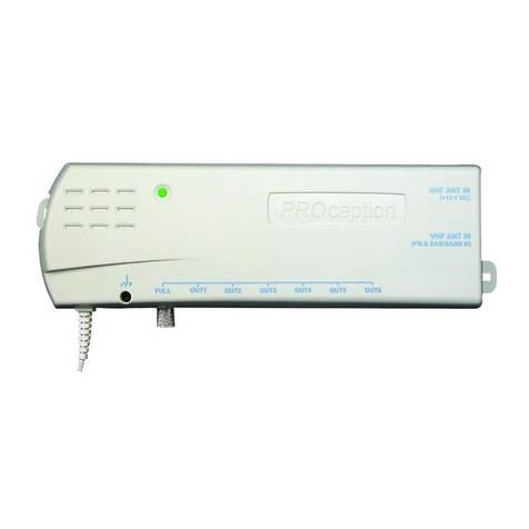
PROception PROAMP24 User manual

4
PD2011-9043-03
2 Year Guarantee
This guarantee covers failure of your PROcepon product resulng from manufacturing defect within a
period of 2 years from the date of supply to the end-user. This guarantee does not cover damage to the
product caused by abuse, tampering, defecve installaon or natural causes such as lightning discharge.
Repair or aempted repair, other than by the manufacturer, will render this guarantee void. This
guarantee does not aect a consumer's statutory rights.
Performance data given are typical unless otherwise stated. We reserve the right to change
product designs and specicaons without prior noce.
EU Declaraon of Conformity
Blake UK hereby declares that the radio equipment type PROAMP24, PROAMP24R, PROAMP26,
PROAMP26R, PROAMP28 and PROAMP28R are in compliance with Direcve 2014/53/EU.
The full text of the EU declaraon of conformity is available at the following internet
address: www.blake-uk.com/DoC
Other Ranges of Products & Services from Blake UK, PROcepon & CappSure...
Website: www.procepon.co.uk
Email: support@procepon.co.uk
©Blake-UK 2018 All rights reserved E&OE Product Specicaon may be Changed without Prior Noce
• TV, Wi-Fi & 4G Aerials www.blake-uk.com/aerials
• Brackets & Installaon Equipment www.blake-uk.com/bracketspoles
• AV TV Wall Mounts www.blake-uk.com/tvbrackets
•CappSure Wi-Fi IP Cameras www.blake-uk.com/cappsure
• Coaxial Connectors & Adaptors www.blake-uk.com/procon
• RF Signal Distribuon www.blake-uk.com/rfsignal
• HDMI Signal Distribuon www.blake-uk.com/hdmi
•LTE Filtering Products www.blake-uk.com/lte
•Satellite Mounts www.blake-uk.com/satmount
•Bespoke Manufacturing www.blake-uk.com/bespoke
•UK R&D www.blake-uk.com/researchdevelop
Related Products: Link to Website:
Setback Ampliers: 1 & 2-Way FM/DAB/UHF Ampliers without IR www.blake-uk.com/amp
PROAMP12R: 2-Way Setback Amplier with IR www.blake-uk.com/ampr
PROSAT1EYE: IR Control Eye 'Magic Eye www.blake-uk.com/eye
PROLINK22: Flexible 'I/O Link' RF Modulator for Sky www.blake-uk.com/prolink22
PROCON01: F Male Twist-On +O-Ring - RG6/100 www.blake-uk.com/procon01
PROCON02: F Male Twist-On +O-Ring Black - RG6/100 www.blake-uk.com/procon02
PROCON12: F Male Crimp-On Black - RG6/100 www.blake-uk.com/procon12
PROCON22: F Male Snap Seal / Compression - RG6/100 www.blake-uk.com/procon22
1
VHF/UHF Distribuon Ampliers Instrucon Manual
PROAMP24-26-28 www.blake-uk.com/distamp
PROAMP24R-26R-28R www.blake-uk.com/ampr
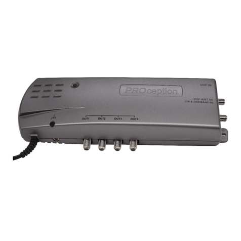
These ampliers are ideal for use in small digital and analogue recepon and distribuon systems. All
MK3 products feature a ltered dual-band VHF input which accepts signals in both Bands II and III,
allowing use for Band III DAB or TV, as well as for FM radio.
All these ampliers are compliant with the Radio Equipment Direcve 2014/53/EU and meet the
harmonised standard EN 303 354 for Class 0. As such they work on ALL current UK DTT channels
including channel 60, are resilient to interference and overloading, and cope with mulple carriers. In
cases of strong LTE interference a separate 4G lter should be ed. These are supplied free by at800,
or higher performance models can be purchased from www.blake-uk.com. (To pass channels up to and
including channel 59 use proLTE1/59, or if channels 58 and 59 are not required, use proLTE1/57).
Features: (Whole Range)
• Separate VHF and UHF inputs.
• New dual-band VHF input for Band II FM radio and Band III DAB or TV.
• 4-, 6- and 8-way versions available.
• Low noise gure and high output capability.
• New equipotenal bonding terminal added on Mk 3 versions.
• Channels 61-68 can be used for locally modulated signals.
Features: (PROAMP24, 26 & 28)
• Tradional mul-way aerial signal ampliers.
• Line power available at UHF input 12V at up to 100 mA.
• Higher-gain FULL output on 6- and 8-way versions allows expansion beyond eight points.
• IEC connectors.
Features: (PROAMP24R, 26R & 28R)
• 7 MHz return path for Sky* infrared remote control systems.
• Built-in power for IR eyes on all outputs.
• F connectors.
Note: R versions do not have input line-power capability or FULL outputs.
Fixing:
Fix the amplier to a sound vercal surface such as a wall, skirng board or equipment mounng board.
Venlaon gaps of at least 50 mm should be le around the front and sides of the unit. More clearance
will be required below the unit to allow access for the signal cables.
Being fully screened, the amplier will not be aected by proximity to an antenna. However clearance
of not less than 300 mm from the nearest part of the antenna should be observed to avoid degrading
the antenna's performance. Manufacturer's instrucons regarding roung of the cable from the
antenna terminal box must be followed if provided.
Do not leave the amplier resng on a carpet or install it where it may become smothered with curtains
or other so furnishing fabrics. When installing the amplier unit in a roof space ensure that it will not
come into contact with thermal insulaon material.
Signal Connecons:
To preserve RF screening integrity the signal connecons to the amplier should be made using good
quality coaxial cable and connectors. This is parcularly important with digital terrestrial TV (DTT) to
minimise the ingress of impulsive electrical interference from home appliances.
• The use of cable benchmarked under the CAI scheme is recommended.
• Ampliers PROAMP24, ‘26 and ‘28 require IEC connectors (IEC 60169-2).
• Ampliers PROAMP24R, ‘26R and ‘28R requires Type-F connectors (IEC 60169-24).

2
Features PROAMP24 & 24R PROAMP26 &26R PROAMP28 &28R
Number of outputs 468
Signal frequency range (VHF) 87.5-108MHz & 174-230MHz 87.5-108MHz & 174-230MHz 87.5-108MHz & 174-230MHz
Signal frequency range (UHF) 470-862MHz 470-862MHz 470-862MHz
Noise gure 3dB 3dB 3dB
Gain to each output (except FULL) 7dB 5dB 5dB
Gain to each FULL output - 16dB 16dB
Output capability (see note below) 86dBµV 82dBµV 82dBµV
IR receiver (‘eye’) line-power 9V@15mA (s/c protected) present at all outputs (‘R’ versions only)
Signal connector type ‘IEC’(IEC 60169-2)
Signal connector type (‘R’ versions) F’(IEC 60169-24)
Mains power requirement 230V 50Hz@2W (8 VA)
Operang temperature range -10 - +40 °C
For both connector types the use of crimp connectors, used in accordance with the manufacturers
instrucons will give the best results. The importance of achieving sound braid connecons cannot be
over-stressed. F connectors should be ghtened with a spanner, not le nger ght.
Important: The FULL output (where ed) must always be terminated in a well matched 75 Ω load. The
terminator plug supplied must be ed if this output is not used.
Using remote control:
The R versions of the ampliers are compable with the PROcepon PROSAT1EYE and other Sky* remote
control extenders. To use the remote control feature it is essenal that the amplier input is fed directly
from the RF OUT-2 connector or I/O port# of the Sky receiver. The amplier provides 9 V DC power for up
to two remote receiver eyes. Note that some Sky receivers require their RFOUT-2 power opon to be
enabled in order for remote control extension to work. On the Sky handset press SERVICES, 4, 0, 1,
SELECT, then select the SECOND OUTLET POWER SUPPLY opon. Set this to be ON, SAVE SETTINGS and
BACK UP out of the menu.
As always with wired remote extender systems, it is essenal to maintain DC connuity through the
coaxial cabling between the amplier output(s) and the IR receiver equipment in the remote room(s). For
this reason isolated outlet plates cannot be used in the remote rooms and all connecons must be
securely clamped, crimped or soldered. When troubleshoong remote control problems, the rst step
should be to check for the presence of approximately 9 V DC on the cable in the remote room.
# I/O Port Replicator needed for Sky box DXR850/890; See Supplementary Installaon Instrucons to
introduce PROcepon proLINK22 ‘RF replicator’.
System equipotenal bonding:
Distribuon systems supplying signals to more than one household should comply with the safety
requirements of BS EN 60728-11. This eecvely requires earthed equipotenal bonding of the system.
(Isolated outlet plates cannot be used with PROAMP R versions for funconal reasons.) Although not
mandatory in single households, system equipotenal bonding is strongly recommended for all
installaons. All PROAMP Mk 3 s are provided with a bonding terminal. A bonding conductor of 4 mm²
should be provided, connected to the main earth terminal of the electrical installaon which supplies the
unit. Bonding may be eected using PROcepon PROBAR5 or 8 equipotenal bonding bar.
Dual-band VHF input:
The VHF input will accept Band II FM radio signals and/or DAB or TV signals in Band III. Separate bandpass
circuits in the amplier provide ltering outside and between these bands. Where more than one aerial is
to be connected a separate diplexer such as the PROcepon proCOM31T should be used (see example in
Fig.1).
Making use of the FULL output:
The FULL output (where ed) allows addional outlets to be fed via an external passive network. This
network should present a good 75 Ω load to the amplier (otherwise the other outputs will be aected).
Fig. 1 shows an example of correct pracce, using an 8-way tap unit to provide eight addional outlets.
The terminator plug supplied must always be ed if the FULL output is not used.
1.Full output is not ed on R versions. 2.Output capability is given for 5 analogue TV channels plus up to 6 DTT
mulplexes at <-14dB relave level (VHF FM and DAB radio signal should not exceed –10dB relave to analogue TV).
3
Safety Instrucons
Overheang:
These ampliers are intended for use in moderate climates only. They should not be used in tropical regions.
The recommended venlaon clearances and other precauons given in the relevant secon of this instrucon
leaet should be observed to prevent overheang. No unit should be xed where it is likely to become
smothered by so furnishing fabrics such as curtains, or by thermal insulaon material in a roof space or
building void. Mains powered equipment should not be le resng on a carpet
Water and re risks:
The appliance is not waterproof. It is intended for indoor use only and must not be xed where it could be
exposed to dripping or splashing water. Objects containing liquids should not be placed on or near the
appliance. To prevent risk of re, no object with a naked ame should be placed on or near the appliance, or its
associated wiring.
Mains plug and disconnecon from the supply:
The appliance is supplied with a standard fused plug ed. If this is unsuitable, refer to the instrucons below. If
you need to change the fuse in the ed plug, a 3 Amp fuse to BS 1362 carrying the ASTA or BSI approval mark
must be used. Always replace the plasc fuse carrier when renewing the fuse. The plug (or other means of
disconnecon from the supply, if used) should remain readily accessible for operaon when necessary. The LED
power indicator on this equipment should not be regarded as providing reliable indicaon of supply
disconnecon.
Changing the plug:
If the ed mains plug is not suitable for the socket-outlets in use, it should be cut o and a new plug ed.
Wiring the new plug: Instrucons supplied with the new plug should be followed. The brown wire must be
connected to the live (L) terminal of the plug and the blue wire to the neutral (N) terminal. Neither wire should
be connected to the earth (E) terminal of a 3-pin plug (the appliance does not require an earth connecon).
Ensure that the cord grip in the plug is correctly used and clamps the sheath of the cord rmly.
Fuse Rang: If the new plug is a fused type, the fuse ed should be rated at not more than 3 Amp.
Cauon: The old plug should be destroyed immediately since it would be dangerous if plugged into a live
socket.
This manual suits for next models
5
Other PROception Amplifier manuals
PROception
PROception proTLA41 User manual
PROception
PROception PROAMP11 User manual

PROception
PROception proAMP11 User manual
PROception
PROception proUSM Series User manual

PROception
PROception proAMP11 User manual
PROception
PROception PROAMP310X User manual

PROception
PROception proAMP108U User manual
PROception
PROception proAMP24 Mk 3 User manual
PROception
PROception proMHD14R Operation and maintenance manual

PROception
PROception proAMP310X User manual
