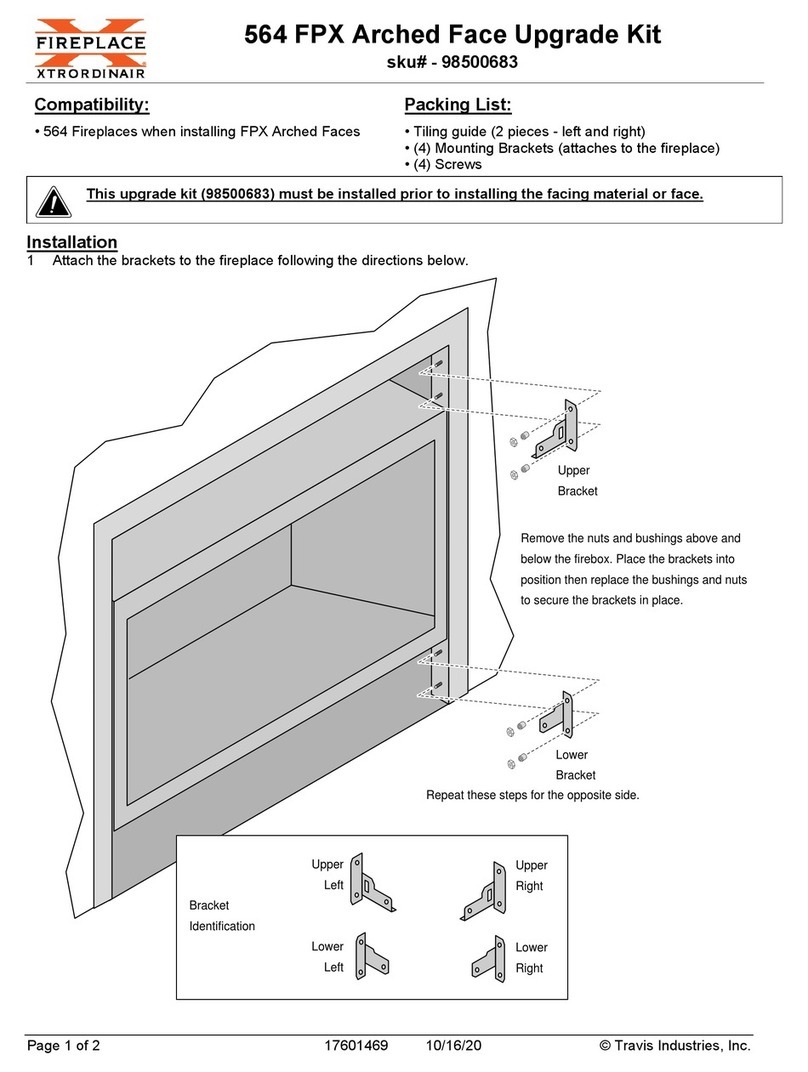
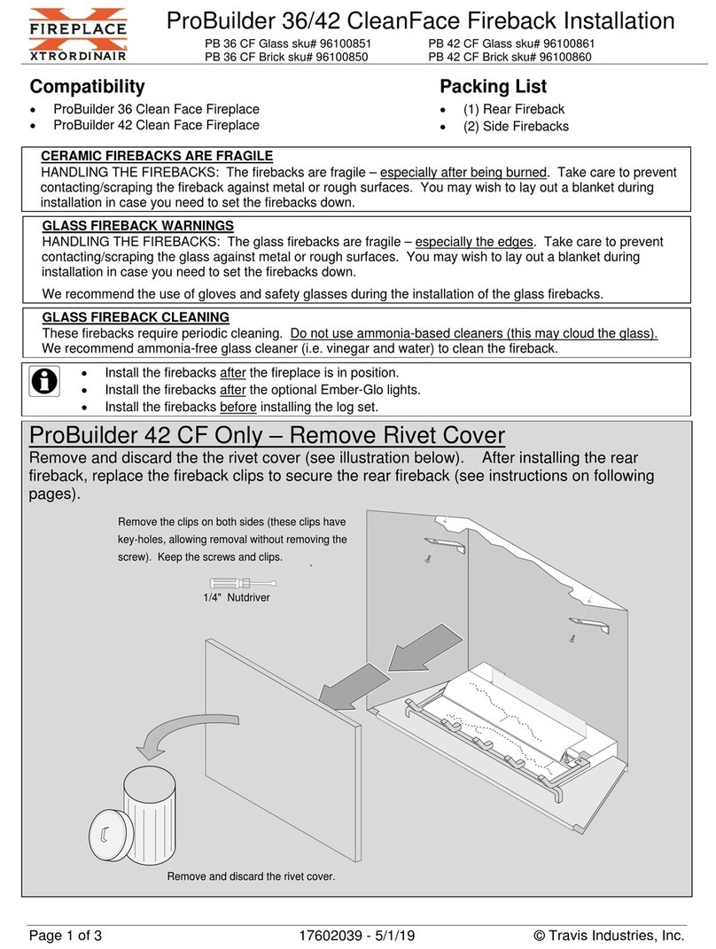
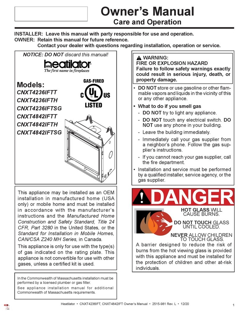
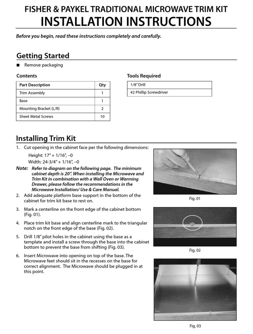
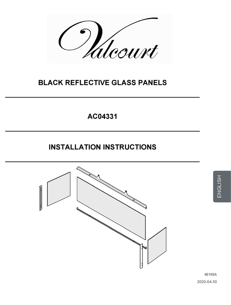
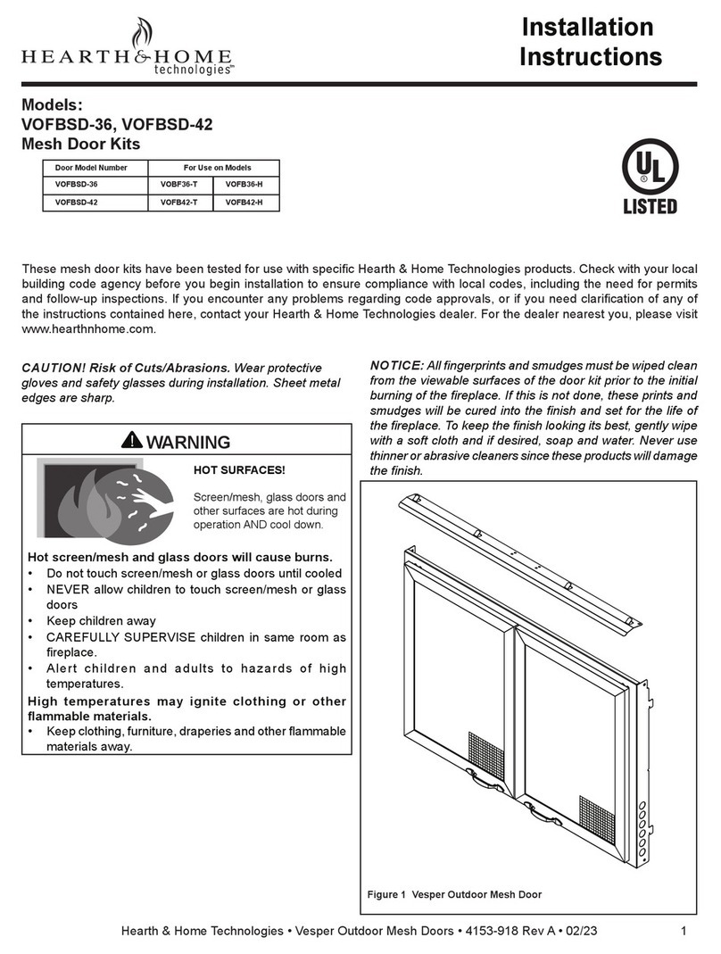
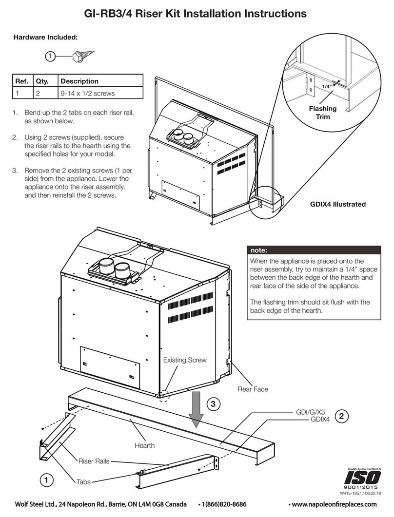
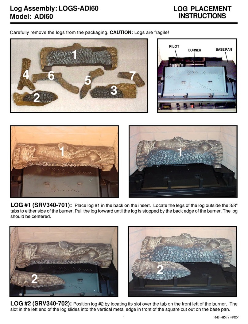
Procom NVDWA1 User manual

Questions, problems, missing parts? Before returning to your retailer, call our
customer service department at 1-866-573-0674, 8:00 a.m - 4:30 p.m., EST,
Español p. 11
ITEM #0011258
MANUAL ON/OFF VALVE
SAFETY PILOT KIT
MODEL # NVDWA1

2
Part Description Quantity
A Propane/LP Burner Air Mixer 1
B Gas Control Valve 1
C Safety Pilot 1
D Pilot Gas Pipe Assembly 1
E Control Knob 1
F Control Rod Extension 1
G18 in. Propane/LP Orice 1
H24 in. Propane/LP Orice 1
I30 in. Propane/LP Orice 1
J Propane/LP Pilot Injector 1
K Self Tapping Screws 4
L Valve Cover 1
M Piezo Ignitor 1
N Control Instructions Label 1
O Gas Inlet Fitting 1
PACKAGE CONTENTS
A
B
C
D
E
F
G
H
I
J
K
L
M
N
O

3
PREPARATION
Before beginning assembly of product, make sure all parts are present. Compare parts with
package contents list. If any part is missing or damaged, do not attempt to assemble the
product. Contact customer service for replacement parts.
Estimated Assembly Time: 60 minutes
Tools Required for Assembly (not included): Philips Screwdriver, Pipe Sealant, Adjustable
Wrench Sediment Trap and Manual Shutoff Valve.
WARNINGS AND CAUTIONS
WARNING
• If the information in this manual is not followed exactly, a re or explosion may result causing
property damage, personal injury, or loss of life.
• Improper installation, adjustment, alteration, service, or maintenance can cause injury or
property damage. Refer to this manual for correct installation and operational procedures.
For assistance or additional information consult a qualied installer, service agency, or the
gas supplier.
• This appliance requires a 1/2 in. NPT (National Pipe Thread) inlet connection to the pressure
regulator.
• A qualied service person must connect log set to gas supply. Follow all local codes.
• Never connect natural gas appliance to private (non-utility) gas wells. This gas is commonly
known as wellhead gas.
• Use pipe joint sealant that is resistant to liquid petroleum (LP) gas.
• Test all gas piping and connections for leaks after installing or servicing. Correct all leaks at
once.
• Never use an open ame to check for a leak. Apply a noncorrosive leak detection uid to all
joints. Bubbles forming show a leak. Correct all leaks at once.
• You must use a ON/OFF safety valve/pilot kit for propane/LP conversion.
CAUTION
• Never connect propane/LP appliance directly to the propane/LP supply. This appliance
requires an external regulator (not supplied). Install the external regulator between the
appliance and propane/LP supply.
• Use only new, black iron or steel pipe. Internally-tinned copper tubing may be used in certain
areas. Check your local codes. Use pipe of 1/2 in. diameter or greater to allow proper gas
volume to log set. If pipe is too small, undue loss of volume will occur.
• For additional convenience and safety, this ON/OFF Valve/Safety Pilot Kit can be used with
natural gas as well. If you are unsure of the proper application, call our customer service at
866-573-0674 for further information.
• If the replace does not have a gas supply shutoff valve, one must be installed.
Helpful Tools (not included): 10 mm Socket or Nut Driver.

4
NATURAL GAS INSTALLATION
1. Thread the gas control valve (B) onto the
burner air mixer (A). Use pipe sealant on the
male threads of the burner air mixer. Hold
the burner air mixer with a wrench to prevent
overtightening the connection to the burner.
Make sure the control rod is facing the front
as shown in Fig. 1.
Fig. 1
A
B
2. Attach the pilot gas pipe assembly (D) to the
safety pilot (C) outlet of the gas control valve (B)
and tighten. Connect the thermocouple to the
rear of the gas control valve (B) as shown in
Fig. 2. C
D
B
Fig. 2
Thermocouple
and Line
3. Install the gas inlet tting (O) into the inlet
opening of the gas control valve (B). Use pipe
sealant on the male pipe threads. Install the gas
connector tube to the gas supply adaptor.
Carefully shape tube and attach to gas inlet
tting (O) as shown in Fig. 3. Be careful not to
cause kinks in tube.
Fig. 3
O
B
Gas
Connector
Tube
Inlet
Opening
Place the burner pan assembly in the center
of the replace oor. Make sure the front of pan
faces forward.

5
4. Install valve cover (L) to burner pan using
two self tapping screws (K) as shown in Fig. 4.
Fig. 4
5. Install safety pilot (C) and piezo ignitor (M)
onto valve cover (L) as shown in Fig. 5. Use two
self tapping screws (K).
Fig. 5
L
K
L
K
M
C
Fig. 6
6. Install the control knob (E) to the control rod
extension (F). Push the control rod extension (F)
onto the “D” shaped control rod through the
center hole in the cover as shown in Fig. 6.
EF
L

6
1. Remove the natural gas burner inlet tting
from the burner pan assembly as shown in
Fig. 1. DO NOT remove the orice from this
tting.
Fig. 1
Fig. 2
2. The propane/LP burner air mixer (A)
included in this kit has 6 holes and must be
used to replace the natural gas inlet
tting. Be sure to use the correct
propane/LP orice for your appliance. This
kit contains additional orices (G or I) as
shown in Fig. 2.
A
G I
or
If you have a 24 in. log set, then the
24 in. propane/LP orice (H), shown in the table
below, is already installed in the propane/LP
burner air mixer (A). Proceed to step 3.
7. When installing this kit on the left hand side of
the burner, adhere control instruction label (N)
onto valve cover (L) as shown in Fig. 7.
Fig. 7
N
L
OFF
PROPANE/LP GAS INSTALLATION

7
Model # Orice Orice #
SSEAV18RP G 18
SSEAV24RP H 24
SSWV24RP H 24
SSWV30RP I 30
The number stamped on orices correspond
to each respective size log set as indicated by
model numbers as shown in table below.
For an 18 in. or 30 in. log set, use a 10 mm
socket or nut driver to remove the orice from the
propane/LP burner air mixer (A).
3. Using pipe sealant on the thread of the larger
end of tting, screw the propane/LP burner air
mixer (A) through hole and into burner manifold
as shown in Fig. 3. Tighten using a wrench.
Fig.3
A
The pilot is provided with a natural gas injector
installed. For Propane/LP gas you must remove
it and replace it with the Propane/LP injector (J)
(“LP” printed on the surface).
1. Gently loosen and remove the pilot gas pipe
from bracket. Replace the injector with the
Propane/LP pilot injector (J) with “LP” printed on
injector surface. Place and tighten the pilot gas
pipe to bracket as shown on Fig 1.
Changing Pilot Orice
J
Fig. 1
Follow steps 1 through 7 under Natural
Gas Installation, page 4.
Continue with step 3 under Natural Gas
Installation, page 4.
OPERATING INSTRUCTIONS

8
REPLACEMENT PARTS
NOTE: Use only original replacement parts. This will protect your warranty coverage for parts
replaced under warranty.
PARTS UNDER WARRANTY
Call Customer Service toll free at (1-866-573-0674) for referral information.
When calling Customer Service, have ready:
• Your name
• Your address
• Model and serial number of your heater
• How heater was malfunctioning
• Type of gas used (Propane/LP or Natural gas/NG)
• Purchase date
• Usually, we will ask you to return the defective part to the factory
PARTS NOT UNDER WARRANTY
Call Customer Service toll free at (1-866-573-0674) for referral information.
When calling Customer Service have ready:
• Model number of your heater
• The replacement part number

9
REPLACEMENT PARTS LIST
For replacement parts, call our customer service department at
1-866-573-0674,
Part.Description Part #
A Propane/LP Burner Air Mixer WAL06-02
B Gas Control Valve NV2050
C Safety Pilot NDW-N600x4
D Pilot Gas Pipe Assembly WAB09
E Control Knob WAL52-01
F Control Rod Extension WAL57-01
G18 in. Propane/LP Orice WAL07-04L
H24 in. Propane/LP Orice WAL07-05L
I30 in. Propane/LP Orice WAL07-06L
J Propane/LP Pilot Injector NDW0811-LP
K Self Tapping Screws ML069-05
L Valve Cover WAL43-01
M Piezo Ignitor ML083-02
N Control Instructions Label WAL17-02
O Gas Inlet Fitting WAL08-03
A
B
C
D
E
F
G
H
I
J
K
L
M
N
O

10
2-YEAR LIMITED WARRANTY
The manufacturer warrants this product to be free from defects in workmanship and material
present at time of shipment from the factory for two (2) years from the date of purchase. This
warranty applies only to the original purchaser. The manufacturer agrees to correct such de-
fect at no charge or, at our option, replace the product with a comparable or superior model.
To obtain warranty service, call our customer service department at 1-866-573-0674. You may
be required to present a copy of your sales receipt as proof of purchase. All costs of removal
and reinstallation are the expressed responsibility of the purchaser. Any damage to the prod-
uct by accident, misuse, improper installation, or by afxing accessories not produced by the
manufacturer, are the purchaser’s responsibility. The manufacturer assumes no responsibility
whatsoever for installation during the warranty period.
There is no further expressed warranty. The manufacturer disclaims any and all implied war-
ranties. The manufacturer shall not be liable for incidental, consequential, or special damages
arising at or in connection with product use or performance except as may otherwise be ac-
corded by law. This warranty gives you specic legal rights, and you also have other rights
which vary from state to state. This warranty supersedes all prior warranties
This product may be covered by one or more of the following patents: (United States) 7013886,
7434447, 7607426, 7654820, (Europe) 07009672, 07024044, 08004868 or other U.S. and foreign
patents pending.
Printed in China
This manual suits for next models
1
Table of contents
Other Procom Fireplace Accessories manuals
Popular Fireplace Accessories manuals by other brands
Jøtul
Jøtul 520 Series Installation and operating instructions

pleasant hearth
pleasant hearth ASTERIA FA311TL manual

FMI
FMI Face Mantels FM36TO Assembly and installation instructions
kozy heat
kozy heat LCK-SF36-D manual

Dimplex
Dimplex DFP4754E install guide

Nordpeis
Nordpeis SA-ME000-W24 Installation and user manual

Lennox Hearth Products
Lennox Hearth Products Stainless Steel Outdoor Weather Cover... installation instructions

Arada
Arada M Series Technical guide

Napoleon
Napoleon DBPB36 installation instructions

Montigo
Montigo M40DV-CR manual

pleasant hearth
pleasant hearth FA010S quick start guide

SimpliFire
SimpliFire SF-CHAF-36 installation instructions