Procon A1M User manual

• i •
Procon
MelcoBEMS MINI (A1M)
FOR INSTALLERS
INSTALLATION MANUAL
Manual version 1.0.16
Firmware version 3.0.15
For safe and correct use, please read this installation manual thoroughly before installing the PROCON
MelcoBEMS MINI (A1M).

• ii •

P
Safe
t
Ca
u
Do no
Op
e
The p
r
Shi
e
Use o
devic
e
shield
e
envir
o
CE
This
p
2014/
3
UL 61
Eur
o
Class
produ
c
and r
e
This i
s
interf
e
A
“De
c
been
m
If this
deter
m
interf
e
If nec
e
exper
i
P
reface
t
y warnin
g
u
tion:
t expose to
r
e
rating Te
m
r
oduct has
b
e
lded Signal
nly shielded
e
to reduce t
h
ed cables e
n
o
nment.
Notice:
p
roduct has
b
3
5/EU (Low
V
010-1 Elect
o
pean Union
A products
a
c
ts may als
o
e
quire the u
s
s
a Class A
p
e
rence in wh
i
c
laration of
C
m
ade and is
equipment
d
m
ined by tur
n
e
rence by on
Reorient t
h
Relocate
t
Move the
e
ssary, con
s
i
enced radio
/
g
s
r
ain or moist
m
perature:
b
een design
e
Cables:
cables for c
o
h
e possibilit
y
n
sures that
y
b
een determ
i
V
oltage Dir
e
rically Safet
y
, Class
A
:
a
re intended
o
be utilized i
s
er to take a
d
p
roduct. In a
i
ch case the
C
onformity” i
available o
n
d
oes cause i
n
n
ing the equ
i
e or more o
f
h
e receiving
t
he Procon
M
Procon Mel
c
s
ult a Procon
/
television o
r
u
re.
e
d to operat
e
o
nnecting p
e
y
of interfere
n
y
ou maintain
i
ned to be in
e
ctive) and 2
0
y
Tested.
for use in n
o
n residential
/
d
equate corr
e
domestic e
n
user may b
e
n accordan
c
n
request.
n
terference
w
i
pment off a
n
f
the followin
g
antenna.
M
elcoBEMS
M
c
oBEMS MI
N
MelcoBEM
S
r
EMC techn
• iii •
e
between -2
0
e
ripherals to
n
ce with rad
the appropr
i
compliance
0
11/65/EU (
R
o
n-residenti
a
/domestic e
n
e
ctive meas
u
n
vironment t
h
e
required to
c
e with the p
r
w
ith radio c
o
n
d on, you a
r
g
measures:
MINI (A1M)
w
N
I (A1M) aw
a
S
MINI (A1
M
ician for ad
d
0
° C and +6
0
any Procon
i
o communi
c
i
ate EMC cl
a
with 2014/3
0
R
oSH Direc
t
a
l/non-dome
s
n
vironments
u
res.
h
is product
m
take adequ
a
r
eceding dir
e
mmunicatio
n
r
e encourag
e
w
ith respect
a
y from the r
M
) technical
s
d
itional sugg
e
0
° C
MelcoBEM
S
c
ations servi
c
a
ssification f
o
0
/EU (EMC
D
ive).
s
tic environ
m
but may ca
u
m
ay cause r
a
a
te measure
s
e
ctives and
s
n
s services,
w
e
d to try to c
o
to the recei
v
e
ceiver.
upport repr
e
e
stions.
S
MINI (A1M
)
c
es. Using
o
r the intend
e
D
irective),
m
ents. Class
u
se interfere
n
a
dio frequen
c
s.
s
tandards h
a
w
hich can b
e
orrect the
v
er.
e
sentative or
)
e
d
A
n
ce
c
y
s
e
an

Disc
l
Wa
r
A
ll pr
o
mater
i
Wa
r
Mitsu
b
We re
by us
use,
n
If the
e
the e
q
l
aimer
r
ranty:
o
ducts manu
f
i
als for a pe
r
r
ning:
b
ishi Electric
serve the ri
g
is believed t
o
n
or for any in
f
e
quipment i
s
q
uipment ma
y
f
actured on
b
r
iod of three
y
UK assum
e
g
ht to chang
e
o
be accura
t
f
ringements
s
used in a
m
y
be impair
e
b
ehalf of Mit
s
y
ears from t
h
s no liability
e
this manu
a
t
e and reliab
l
of patents o
r
m
anor not sp
e
d.
• iv •
subishi Elec
t
h
e date of d
e
for damage
s
a
l at any tim
e
l
e. However
,
r other right
s
e
cified by th
e
t
ric UK are
w
e
livery to th
e
s
conseque
n
e
without noti
,
no respons
s
of third par
t
e
manufactu
w
arranted ag
a
original pur
c
t to the user
ce. The info
r
i
bility is ass
u
t
ies resultin
g
r
er, the prot
e
ainst defecti
c
haser.
r
of this prod
u
r
mation furn
i
u
med by us
f
g
from its us
e
e
ction provid
v
e
u
ct.
i
shed
f
or its
e
.
ed by

• v •
Amendment Register
Document
Version
Latest
Firmware
Version
Date Author Notes
1.0.0
3.0.0 08/05/15 GD Initial version for firmware V1.0.0
1.0.1 3.0.1 16/06/15 GD
Added ‘Applicable Unit Type’ columns to Air-To-Water Modbus
tables.
Other minor modifications.
1.0.2 3.0.1 20/08/15 GD
More FTC5 model types added to ‘Appendix B - Compatible Air-To-
Water units’.
1.0.3 3.0.1 20/08/15 GD
FTC5 controller type PAC-IF062B-E added to ‘Appendix B -
Compatible Air-To-Water units’.
1.0.4 3.0.6 19/01/16 GD
Added ATW Modbus registers for measured energy consumed and
measured energy produced.
1.0.5 3.0.11 15/06/16 GD Changes to BACnet section.
1.0.6 3.0.11 23/08/16 GD Minor changes.
1.0.7 3.0.12 01/08/16 GD Added Flow Rate Modbus registers for ATW units.
1.0.8 3.0.12 21/10/16 SC / GD Added warning paragraph on page iii.
Added MET lab logo.
1.0.9 3.0.12 14/11/16 GD Updated MET lab logo.
1.0.10 3.0.12 24/04/17 GD Updated Appendix A – Compatible Air-To-Air units
1.0.11 3.0.13 19/06/17 GD Latest firmware version updated to 3.0.13
1.0.12 3.0.13 31/07/17 GD
Added information to Installation section regarding connections to
twin/triple/quad and MXZ systems.
Correction made to section 2, the name MAC-399IF replaced with
MAC-333IF.
1.0.13 3.0.13 25/08/17 GD
Modbus tables updated for QAHV units.
QAHV-N560YA-HPB added to the compatible units list.
1.0.14 3.0.13 01/11/17 GD
Modbus tables updated for EAHV units.
Numerous changes to Modbus tables due to updated protocol
documentation.
1.0.15 3.0.15 08/11/17 GD
Added new Modbus tables for Lossnay units (firmware version must
be 3.0.15 or later).
Added firmware revision history table.
Updated image in Figure 1.
Modbus tables now have row headings at the top of every page.
Added text to section 2.Overview
1.0.16 3.0.15 13/02/18 GD
Updated Modbus tables and Lossnay unit compatibility list. VL
series Lossnay unit are not supported.
Any additional notes since printing will be appended to the rear of this document on separate
sheets of paper.

• vi •
Firmware revision history
Firmware
Version Date Notes
3.0.0 23/02/15 - Initial version of firmware with BACnet support for ATA protocol.
3.0.1 12/06/15
- Fixed bug so the ‘Outdoor Temperature By BMS’ Modbus register reports the
correct value.
3.0.2 19/08/15
- DegF to DegC temperature conversions changed to be more accurate.
- Removed BACnet objects for Heating and Cooling Setpoints.
- BACnet PRESENT_VALUE property now writable for Analog Inputs if they are
currently out of service.
- Added range checking to BACnet Multi State Output object types when writing to
the PRESENT_VALUE property.
3.0.3 06/10/15 - Removed the Min/Max Present Value properties for the Setpoint BACnet object.
3.0.4 29/10/15 - Minor changes to allow support for BACnet protocol revision 12.
3.0.5 - Version not released
3.0.6 15/01/16 - Added support for ATW energy monitoring commands
3.0.7 19/01/16 - Minor changes to aid BTL certification testing.
3.0.8 21/04/16 - Fixed minor bugs reported during BTL testing.
3.0.9 16/05/16 - Fixed more minor bugs reported during BTL testing.
3.0.10 19/05/16 - BACnet Device Object OBJECT_NAME property now writable.
3.0.11 19/05/16 - Fixed minor bug reported during BTL testing.
3.0.12 27/07/16
- Added support to read Flow Rate value for ATW units, value exposed as a Modbus
register.
- Fixed bug so Modbus writes are always actioned correctly.
- This firmware version passed BTL testing.
3.0.13 03/04/17
- Change so writable (not commandable) Analog Value BACnet objects accept and
action PRESENT_VALUE write commands for every priority value. The priority array
is not updated though and all values remain NULL.
3.0.14 26/09/17
- Communication with connected unit is now reinitialised after if there has been no
successful comms for a period of 1 minute.
3.0.15 09/11/17
- Added Modbus support for Lossnay units.
- Fixed bug so Modbus comms counter Modbus register increments correctly.

1
[
[
Fig. 1]
B
A
A RS-4
8
B CN10
5
8
5 connector
5/CN92 conn
e
5
e
ction lead
2
[Fig. 2
]
]
Air to
a
Air to
w
a
ir unit
w
ater unit
6

7
Contents
Preface ........................................................................................................................................................................... iii
Safety warnings...........................................................................................................................................................iii
Disclaimer....................................................................................................................................................................iv
Amendment Register ..................................................................................................................................................... v
Firmware revision history............................................................................................................................................. vi
1.Safety precautions................................................................................................................................................ 8
2.Overview................................................................................................................................................................ 9
3.DIP switch settings............................................................................................................................................. 10
3.1.RS-485 Node address.................................................................................................................................. 10
3.2.RS-485 communication settings................................................................................................................... 10
3.3.Protocol selection ......................................................................................................................................... 11
3.4.Deadband mode........................................................................................................................................... 11
4.Deadband Mode.................................................................................................................................................. 12
4.1.Settings ........................................................................................................................................................ 12
4.2.Operation ..................................................................................................................................................... 12
4.3.Initialisation .................................................................................................................................................. 13
5.Setpoint Offset.................................................................................................................................................... 14
5.1.Settings ........................................................................................................................................................ 14
5.2.Operation ..................................................................................................................................................... 14
6.RS-485 termination ............................................................................................................................................. 16
7.Installation........................................................................................................................................................... 17
7.1.Physical connection...................................................................................................................................... 17
7.2.Power supply................................................................................................................................................ 17
7.3.Modbus connections .................................................................................................................................... 17
7.4.Unit type selection ........................................................................................................................................ 17
7.5.Using Twin/Triple/Quad systems.................................................................................................................. 18
7.5.1.When fault Modbus register is being used ............................................................................................ 18
7.5.2.When fault Modbus register is not being used ...................................................................................... 18
7.6.Using single split units in a group ................................................................................................................. 19
7.6.1.When fault Modbus register is being used ............................................................................................ 19
7.6.2.When fault Modbus register is not being used ...................................................................................... 19
7.7.Using MXZ split units.................................................................................................................................... 20
8.Status LEDs ........................................................................................................................................................ 21
8.1.AC ACK........................................................................................................................................................ 21
8.2.RS-485 ACK................................................................................................................................................. 21
9.BACnet ................................................................................................................................................................ 22
9.1.BACnet MS/TP ............................................................................................................................................. 22
9.2.BTL Listing ................................................................................................................................................... 22
9.3.Object types supported ................................................................................................................................ 23
9.4.Object list ..................................................................................................................................................... 24
10.Modbus connection............................................................................................................................................ 25
10.1.Modbus background..................................................................................................................................... 25
10.2.Modbus registers.......................................................................................................................................... 25
10.3.Modbus connections .................................................................................................................................... 25
11.Modbus tables – Air-To-Air systems................................................................................................................. 27
11.1.Holding registers .......................................................................................................................................... 27
11.2.Input registers............................................................................................................................................... 29
11.3.Discrete Inputs ............................................................................................................................................. 30
11.4.Coils ............................................................................................................................................................. 30
12.Modbus tables – Air-To-Water systems............................................................................................................ 31
12.1.Holding registers .......................................................................................................................................... 31
12.2.Input registers............................................................................................................................................... 55
12.3.Coils ............................................................................................................................................................. 69
12.4.Discrete Inputs ............................................................................................................................................. 70
13.Modbus tables – Lossnay systems................................................................................................................... 75
13.1.Holding registers .......................................................................................................................................... 75
13.1.Input registers............................................................................................................................................... 82
13.1.Coils ............................................................................................................................................................. 85
13.1.Discrete Inputs ............................................................................................................................................. 85
Appendix A – Compatible Air-To-Air units................................................................................................................. 88
Appendix B – Compatible Air-To-Water units............................................................................................................ 90
Appendix C – Compatible Lossnay units................................................................................................................... 91

1. Safe
t
Symbols us
e
Warning:
Describes pr
e
Caution:
Describes pr
e
Warning
:
•Ask the d
e
-Imprope
r
•Use the s
p
not appli
e
-Inadequ
a
•Never rep
- If the uni
t
•Have all e
Regulatio
- If the po
w
•Keep the
e
- Contact
m
•To dispo
s
Caution:
•Safely di
s
- Packing
m
- Tear apa
which has
¾Befor
e
“Safet
y
¾The “
S
re
g
ard
t
y preca
u
ed in the tex
t
e
cautions that
e
cautions that
:
e
aler or an au
t
r
installation by
t
p
ecified cable
s
e
d to the termi
n
a
te connection
a
p
air the unit. If
t
t
is repaired im
p
e
lectric work d
o
ns" and the in
s
w
er source cap
a
e
lectric parts
a
m
ay result in el
e
s
e of this prod
u
s
pose of the p
a
m
aterials, such
rt and throw a
w
not been torn
a
e
installing the
y
precautions
”
S
afety precauti
o
in
g
safet
y
. Ma
k
u
tions
t
should be ob
s
should be ob
s
t
horised techn
i
t
he user may r
e
s
for wiring. M
a
n
als
a
nd fastening
m
t
he controller
m
p
roperly, electri
c
o
ne by a licen
s
s
tructions giv
e
a
city is inadequ
a
a
way from any
e
ctric shock, fir
e
u
ct, consult y
o
a
cking materia
l
as nails and ot
h
w
a
y
plastic pack
a
part, they face
unit, make su
r
”
o
ns” provide
v
k
e sure
y
ou fo
s
erved to prev
e
s
erved to prev
e
i
cian to install
e
sult in electric
s
a
ke the conne
c
m
a
y
generate he
m
ust be repair
e
c
shock, or fire
m
s
ed electrician
e
n in this man
u
a
te or electric
w
water - washi
n
e
or smoke
o
ur dealer
l
s
h
er metal or wo
aging bags so
t
the risk of suff
o
r
e you read all
v
ery important
l
low them
e
nt danger of i
n
e
nt damage to
the unit
s
hock, or fire
c
tions securel
y
e
at and cause a
r
ed, consult th
e
m
ay result
according to
"
u
al and alway
s
w
ork is perform
e
n
g water etc…
o
oden parts, ma
t
hat children wil
o
cation
the
points
n
jury or death
the unit.
y
so that any
o
fire
e
dealer
"
Electric Facili
t
s
use a special
e
d improperly, e
y cause stabs
o
l not play with t
h
to the user.
utside forces
a
t
y Engineerin
g
circuit
lectric shock a
n
o
r other injuries
h
em - If childre
n
a
cting on the
c
g
Standard", "I
n
n
d fire may res
u
n
play with a pl
a
8
c
ables are
n
terior Wire
u
lt
a
stic bag

2. Over
v
The Procon
M
products (M-
as a gatewa
y
The MelcoB
E
Because the
available to
e
and change
d
The MelcoB
E
Compatible
m
Caution:
MAC-397IF
a
CN105/CN9
2
Appendix A l
Appendix B l
Appendix C l
Figure 1 sh
o
Figure 2 sh
o
both Air-to-A
ATA – Mo
ATW Eco
d
E Series
C
Lossnay
–
v
iew
M
elcoBEMS
M
, S- and P-se
r
y
between the
E
MS MINI (A1
reading is co
n
e
xternal devic
e
d
via this conn
E
MS MINI (A1
m
odel numbe
r
a
nd MAC-333
2
connector is
ists the comp
a
ists the comp
a
ists the comp
a
o
ws the Melco
o
ws the CN10
5
ir and Air-To-
W
dbus RTU
d
an Heatin
C
hillers –
O
–
Only Mo
d
M
INI (A1M) P
r
r
ies split air c
o
system and
e
M) continuou
s
n
tinuous the
M
e
s through th
e
ection. Pleas
e
M) is powere
d
r
s can be fou
n
IF units cann
o
used.
a
tible Air-To-
A
a
tible Air-To-
W
a
tible Lossna
y
BEMS MINI (
A
5
/CN92 conn
e
W
ater type u
n
and BACn
g Product
s
O
nly Modb
u
d
bus RTU
A
r
otocol Conve
r
o
nditioning sy
s
e
xternal third
p
s
ly reads dat
a
M
elcoBEMS
M
e
RS-485 port
e
refer to the
M
d
via the CN1
0
n
d in the appe
n
o
t be connect
e
A
ir indoor unit
s
W
ater indoor
u
y
units.
A
1M) convert
e
e
ctor on the i
n
its.
et MS/TP
A
s
– Only M
o
u
s RTU
A
v
a
A
vailable
r
ter is used fo
s
tems) and Ai
p
arty equipm
e
a
from the sys
t
M
INI (A1M) al
w
t
using the M
o
M
odbus secti
o
05/CN92 con
n
ndices of this
e
d when the
M
s
.
u
nits.
e
r.
n
door unit PC
B
A
vailable
o
dbus RT
U
a
ilable
r remote mon
r-to-Water pr
o
e
nt.
t
em and chan
w
ays stores u
p
o
dbus RTU so
f
o
n for further i
n
n
ector, hence
document.
M
elcoBEMS
M
B
that the Mel
c
U
A
vailabl
e
i
toring and co
n
o
ducts (CAHV
g
es configura
t
p
-to-date data
f
tware protoc
o
n
formation.
no external p
o
INI (A1M) is
c
c
oBEMS MIN
I
e
ntrol of both
A
V
, CRHV, PW
F
a
tion when ne
c
a
. This data is
o
l. Values can
ower supply i
s
c
onnected, as
I (A1M) conn
e
9
A
ir-to-Air
F
Y). It acts
c
essary.
then
be read
s
needed.
the same
e
cts to, for

10
3. DIP switch settings
There is a bank of 8 DIP switches on the MelcoBEMS MINI (A1M) labeled ‘CONFIGURATION’. These switches are
used to configure communication settings and to enable some features.
3.1. RS-485 Node address
When BACnet MS/TP protocol has been selected (see section 3.3) the node address is used as the Station ID.
When Modbus RTU protocol has been selected (see section 3.3) The node address is used as the Slave ID.
Any node address in the range 1 – 30 can be chosen using switches 1 – 5. The address is set in binary, where the
switch positions have the following values:
Switch number Value when switch is set to ON
1 1
2 2
3 4
4 8
5 16
To get the node address, add together the value for each switch set ON. For example, to set address 13, set switches
1, 3 and 4 ON (1 + 4 + 8 = address 13).
When all switches 1 – 5 are set to the ON position the node address is set in software by writing to a Modbus register
(see Modbus Holding Registers section).
Note: When all switches are set to the OFF position a node address of 1 is assumed.
Note: Each MelcoBEMS MINI (A1M) connected on the same RS-485 network must be set to a unique node address.
3.2. RS-485 communication settings
The RS-485 settings are set using DIP switch 6.
When the switch is in the OFF position the Baud Rate and Parity settings are set in software by writing to Modbus
registers (see Modbus Holding Register section).
Switch 6 RS-485 communication settings
OFF Baud Rate and Parity set in software
ON 9600 baud, no parity
The number of data bits is fixed at 8 and the number of stop bits is fixed at 1.

11
3.3. Protocol selection
The RS485 protocol is set using DIP switch 7.
When the switch is in the ON position the Modbus RTU protocol is selected.
Switch 7 Protocol selection
OFF BACnet MS/TP
ON Modbus RTU
3.4. Deadband mode
The Deadband feature can be enabled using DIP switch 8.
When the switch is in the OFF position the Deadband feature is disabled.
When the switch is in the ON position the Deadband feature is enabled.
Switch 8 Deadband feature
OFF Disabled
ON Enabled

4. Dea
d
The deadba
n
4.1. S
e
There are tw
o
changed via
The Cooling
will be assu
m
4.2. O
p
When enabl
e
air) Temper
a
While the ro
o
Whilst in HE
A
Whilst in FA
N
setpoint of 1
9
Whilst in CO
O
Whilst in FA
N
setpoint of 2
8
The followin
g
d
band M
o
n
d mode is en
e
ttings
o
settings, th
e
Modbus, refe
r
Setpoint mus
t
m
ed.
p
eration
e
d, the Melco
B
a
ture.
o
m temperatu
r
A
T mode, if th
N
mode, if the
9
ºC.
O
L mode, if t
h
N
mode, if the
8
ºC.
g
image show
s
o
de
abled by setti
n
e
Heating Set
p
r
to the Air-T
o
t
be at least 2
º
B
EMS MINI (
A
r
e is less tha
n
e room temp
e
temperature
r
h
e room temp
e
room temper
a
s
this graphic
a
n
g DIP switch
p
oint (default
1
-Air Modbus t
º
C greater th
a
A
1M) controls
the Heating
S
e
rature rises
a
r
ises above t
h
e
rature falls b
e
a
ture falls bel
o
a
lly (assumin
g
h
8 ON. It is o
n
1
9º) and Cool
t
ables for mor
e
a
n the Heatin
g
the Mode an
d
S
etpoint the u
a
bove the He
a
h
e Cooling Se
t
e
low the Coo
l
ow
the Heati
n
g
a Heating S
e
n
ly applicable
ing Setpoint (
d
e
information.
g
Setpoint, oth
d
Temperatur
e
nit will be set
a
ting Setpoint
t
poin
t
the unit
l
ing Setpoint
–
n
g Setpoin
t
th
e
e
tpoint of 19º
C
t
o Air-To-Air t
y
d
efault 23ºC).
erwise the de
f
e
Setpoint ba
s
t
o HEAT mod
+
1º
C
the unit
will be set to
–
1ºC the unit
w
e
unit will be s
e
C
and a Cooli
n
t
ype units.
These value
s
e
fault values g
s
ed on the Ro
o
e with a setp
o
t
will be set to
COOL mode
w
will be set to
F
et to HEAT m
n
g Setpoint o
f
12
s
can be
iven above
o
m (return
o
int of 28ºC.
FAN mode.
w
ith a
F
AN mode.
ode with a
23ºC):

13
4.3. Initialisation
When the MelcoBEMS MINI (A1M) powers up it will set the mode, which will be determined by the room temperature.
If less than the Heating Setpoint the unit will be set to HEAT mode with a setpoint of 28ºC.
If greater than or equal to the Cooling Setpoint the unit will be set to COOL mode with a setpoint of 19ºC.
If between the Heating and Cooling Setpoints the unit will be set to FAN mode.
5. Setp
o
The Setpoin
t
5.1. S
e
There are tw
o
Setpoint.
The BMS Vi
r
if the Melco
B
The BMS R
o
lost and res
e
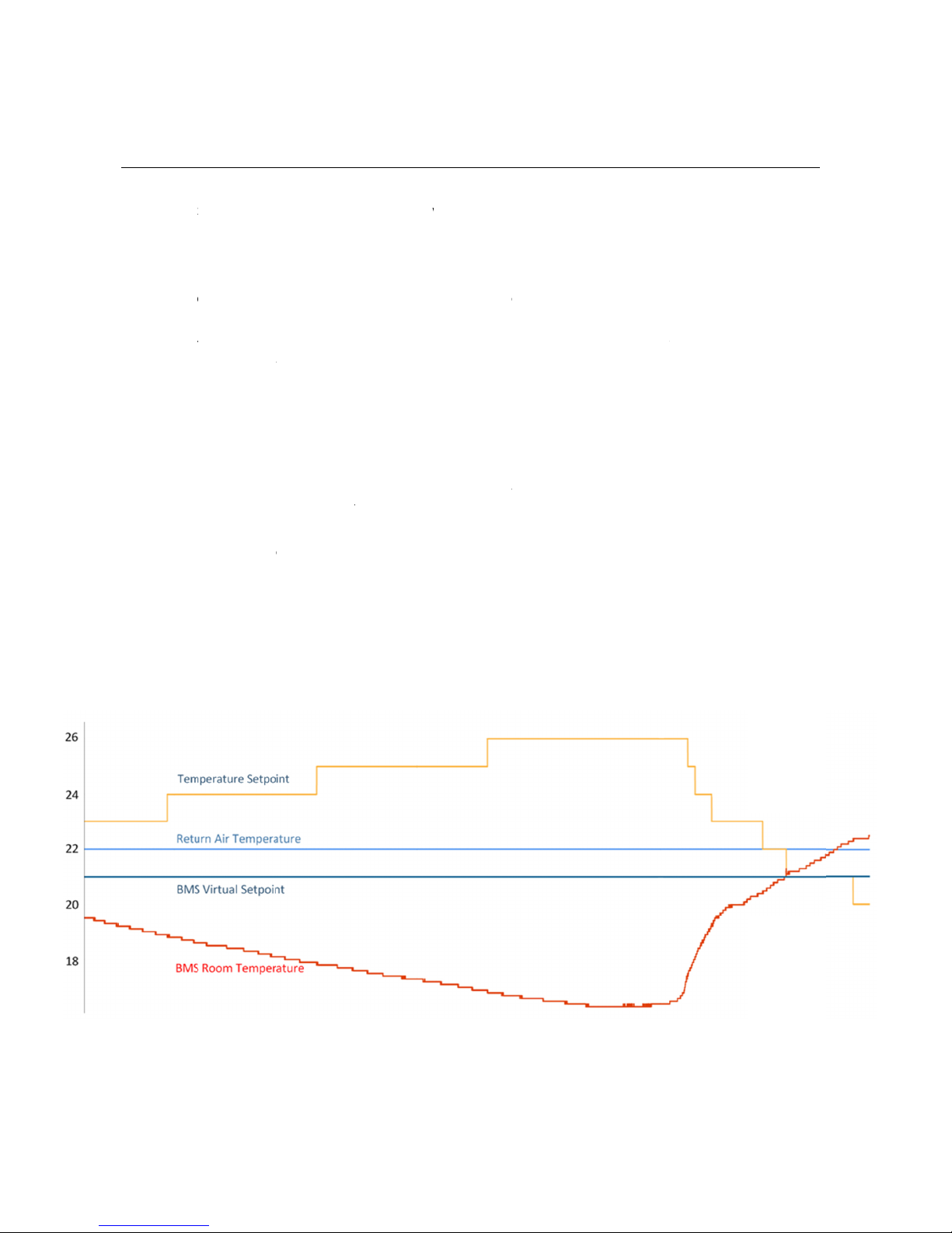
5.2. O
p
In some situ
a
accurate te
m
between the
s
The new te
m
Temperatur
e
As a hypoth
e
temperature
increases th
e
When the B
M
Hysteresis h
a
o
int Off
s
t
Offset featur
e
e
ttings
o
settings whi
r
tual Setpoint
c
B
EMS MINI (
A
o
om Tempera
t
e
t to zero upo
n
p
eration
a
tions a 3
rd
p
a
m
perature rea
d
s
e two tempe
r
m
perature set
p
e
Setpoint =
R
e
tical exampl
e
remaining co
n
e
indoor unit’s
M
S Room Te
m
a
s been built i
s
et
e
is only appli
c
ch are applic
a
c
an be chang
e
A
1M) loses po
w
t
ure can be c
h
n
the MelcoB
E
a
rty room tem
p
d
ing than the
r
r
ature reading
p
oint is calcul
a
R
eturn Air T
e
e
, consider th
e
n
stant at 22º
C
temperature
m
perature rea
c
n to prevent t
h
c
able to, and
w
a
ble to the Se
t
e
d using Mod
b
w
er.
h
anged using
M
E
MS MINI (A1
p
erature sens
o
r
eturn air tem
p
s and compe
n
a
ted using the
e
mperature –
e
BMS Virtual
S
C
. As the BMS
s
etpoint.
c
hes 18ºC th
e
h
e temperatu
r
w
ill only be e
n
t
point Offset f
e
bus and is st
o
M
odbus but i
s
M) losing po
w
o
r connected
t
p
erature of th
e
n
sate by adju
s
following equ
(BMS Room
Setpoint bein
g
Room Temp
e
e
Temperatur
e
r
e setpoint fro
n
abled for, Air
-
e
ature, BMS
R
o
red in non-vo
s
not stored in
w
er.
t
o a BMS or
o
e
indoor unit.
T
s
ting the indo
o
ation:
Temperatur
e
g
set to 21ºC
a
e
rature decre
a
e
Setpoint = 2
2
m rapidly cha
-
To-Air type u
R
oom Tempe
r
latile memory
non-volatile
m
o
ther controlle
r
T
he A1M can
c
o
r unit’s temp
e
e
– BMS Virt
u
a
nd the indoo
r
a
ses the Melc
o
2
– (18 – 21)
=
n
ging.
nits.
r
ature and B
M
y
so the value
m
emory, so th
r
may provide
calculate the
d
e
rature setpoi
n
u
al Temperat
u
r unit return a
oBEMS MINI
=
25ºC.
14
M
S Virtual
is retained
e value is
a more
d
ifference
n
t.
u
re)
ir
(A1M)

15
The setpoint offset will only operate correctly if the BMS Room Temperature is periodically updated via Modbus, to
ensure the MelcoBEMS MINI (A1M) always has an up to date reading.
If the BMS Room Temperature is set to 0ºC (which it will be on power up) the setpoint offset feature will be disabled. It
will only activate when the BMS Room Temperature is not 0ºC.
To disable the feature without removing the MelcoBEMS MINI (A1M) power, simply set the BMS Room Temperature to
0ºC.

16
6. RS-485 termination
An RS-485 termination resistor can be enabled on the MelcoBEMS MINI (A1M) PCB using the single jumper labeled
J1.
The jumper setting is summarised below:
Jumper Setting Description
Not fitted Termination resistor not enabled
Fitted Termination resistor enabled

17
7. Installation
7.1. Physical connection
The MelcoBEMS MINI (A1M) has a 1 metre flying lead to connect directly into the CN105/CN92 connector on the
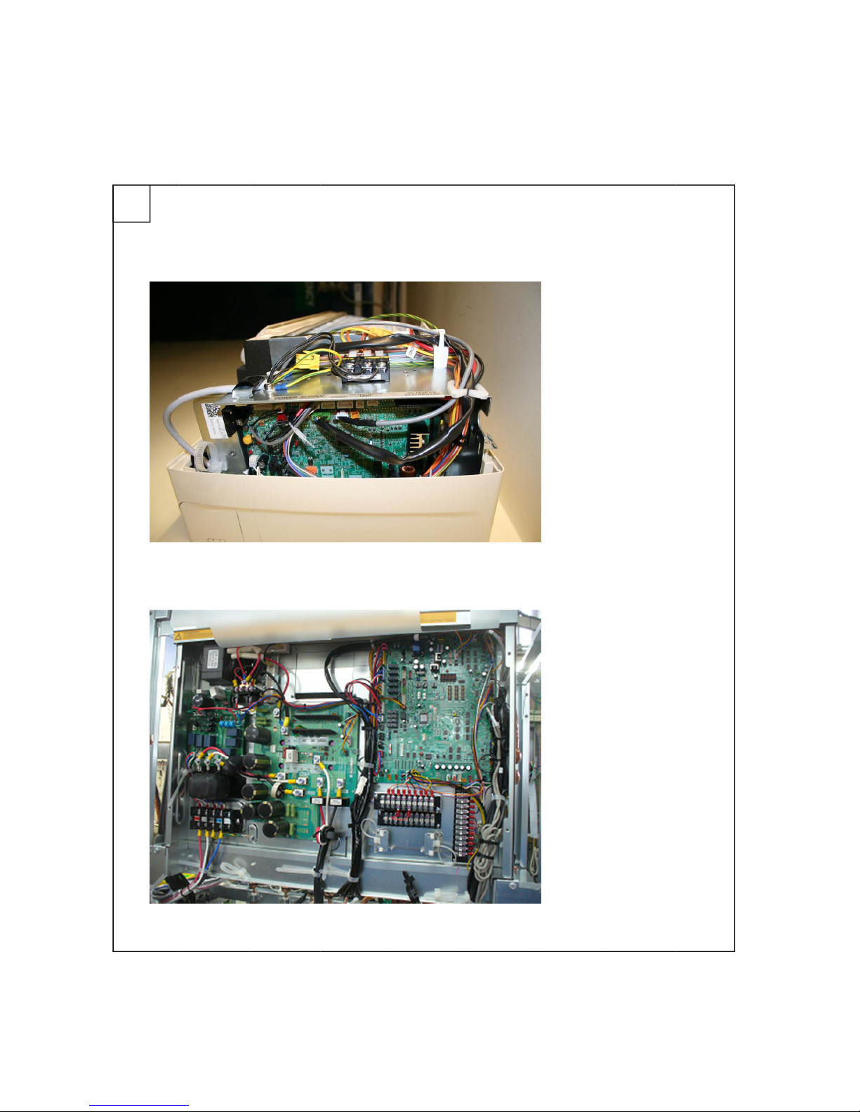
controller PCB. As an example, Figure 2 shows this connection on a Mr Slim indoor unit and a CRHV unit.
7.2. Power supply
The MelcoBEMS MINI (A1M) is powered from the CN105/CN92 air conditioner host connector at 12V DC and therefore
does not require an external power supply.
7.3. Modbus connections
The MelcoBEMS MINI (A1M) has a 3-way screw terminal to provide Modbus RTU communication via RS-485. Figure 1
shows the RS-485 connections. The Modbus section contains further detail of the Modbus communications.
7.4. Unit type selection
The MelcoBEMS MINI (A1M) software will automatically detect whether an Air-To-Air or Air-To-Water unit is connected.
It will then only send commands applicable to that unit type.

7.5. U
s
It is recomm
e
then one Me
l
7.5.
7.5.
s
ing Twin
/
e
nded to use
o
l
coBEMS MI
N
1. When faul
t
2. When faul
t
/
Triple/Q
u
o
ne MelcoBE
M
N
I can be use
d
t
Modbus re
g
t
Modbus re
g
u
ad syste
m
M
S MINI for e
d
per twin / tri
p
g
ister is bein
g
g
ister is not
b
m
s
e
ach indoor u
n
p
le / quad sys
t
g
used
b
eing used
n
it, however, i
f
t
em.
f
the fault Mo
d
d
bus register i
s
18
s
not used
This manual suits for next models
1
Table of contents
Other Procon Media Converter manuals


Popular Media Converter manuals by other brands

Axis
Axis Q7900 Rack installation guide

Crystal Vision
Crystal Vision DEC105S user manual

Hervisa Perles
Hervisa Perles BLOCK M-1 Operator's manual

Riello
Riello RLAS 650-800 FGR 6 Installation, use and maintenance instructions

Phoenix Contact
Phoenix Contact QUINT4-PS/48-110DC/24DC/2.5/ PT manual

Absolute Process Instruments
Absolute Process Instruments DuoPak APD 2067 manual


