PROCRAFT 512000 User manual
512000
AC/DC 200AMP INVERTER
PULSE TIG / MMA WELDER
WARNING!
READ AND UNDERSTAND ALL INSTRUCTIONS
Failure to follow all instructions listed below may result
in electric shock, re, and/or serious injury.
SAVE THESE INSTRUCTIONS
Keep this manual for the safety warnings and precautions,
assembly, operating, inspection, maintenance and
cleaning procedures. Write the product’s serial number
in the back of the manual (or month and year of purchase
if product has no number). Keep this manual and the
receipt in a safe and dry place for future reference.
OPERATING INSTRUCTIONS
PROCRAFT

Page 2
CONTENTS
Safety warnings ............................................................................................................3
Description of this welder ............................................................................................9
Table of technical Parameters....................................................................................10
Description of the panel function ...............................................................................11
Protection against overheating ................................................................................. 13
Welding with elementary electrodes (MMA method)............................................... 13
Welding with a non-combustible electrode in an inert gas shield (TIG method).... 14
Welding with remote control..................................................................................... 16
Routine maintenance ................................................................................................. 17
Precautions before repairs......................................................................................... 18
Precautions or preventive measures ......................................................................... 19
Troubles may be encountered in welding.................................................................. 19
Trouble shooting ........................................................................................................ 21
Included Standar Accessories....................................................................................23

Page 3
SAVE THIS MANUAL
Keep this manual for the safety
warnings and precautions, assembly,
operating, inspection, maintenance and
cleaning procedures. Write the product’s
serial number in the back of the manual
near the assembly diagram (or month and
year of purchase if product has no
number). Keep this manual and the receipt
in a safe and dry place for future
reference.
IMPROTANT SAFETY INFORMATION
In this manual, on the labeling, and all
other information provided with this
product:
This is the safety alert symbol. It is
used to alert you to potential personal
injury hazards. Obey all safety
messages that follow this symbol to
avoid possible injury or death.
DANGER indicates a hazardous
situation which, if not avoided, will
result in death or serious injury.
WARNING: WARNING indicates a
hazardous situation which, if not
avoided, could result in death or
serious injury.
CAUTION: CAUTION, used with
the safety alert symbol, indicates a
hazardous situation which, if not
avoided, could result in minor or
moderate injury.
NOTICE:NOTICE is used to
address practices not related to
personal injury.
SAFETY WARNINGS AND
PRECAUTIONS
WARNING: When using tool, basic safety
precautions should always be followed to
reduce the risk of personal injury and
damage to equipment.
Read all instructions before using this
tool!
Work Area Precautions
1. Keep your work area clean and well
lit. Cluttered benches and dark areas
invite accidents.
2. Do not operate power tools in
explosive atmospheres, such as in
the presence of flammable liquids,
gases, or dust. Power tools create
sparks which may ignite the dust or
fumes.
3. Keep bystanders, children, and
visitors away while operating a
power tool. Distractions can cause
you to lose control. Protect others in
the work area from debris such as
chips and sparks. Provide barriers or
shields as needed.
WARNING!
READANDUNDERSTANDALL
INSTRUCTIONS
Failuretofollowallinstructionslistedbelow
mayresultinelectricshock,fire,and/or
seriousinjury.
SAVETHESEINSTRUCTIONS

Page 4
Electrical Safety
1. Grounded tools must be plugged
into an outlet properly installed and
grounded in accordance with all
codes and ordinances. Never
remove the grounding prong or
modify the plug in any way. Do not
use any adapter plugs. Check with
a qualified electrician if you are in
doubt whether the outlet is properly
grounded. If the tool should
electrically malfunction or break down,
grounding provides a low resistance
path to carry electricity away from the
user.
2. Double insulated tools are
equipped with a polarized plug (one
blade is wider than the other). This
plug will fit in a polarized outlet
only one way. If the plug does not
fit fully in the outlet, reverse the
plug. If it still does not fit, contact a
qualified electrician to install a
polarized outlet. Do not change the
plug in any way. Double insulation
eliminates the need for the three wire
grounded power cord and grounded
power supply system.
3. Avoid body contact with grounded
surfaces such as pipes, radiators,
ranges, and refrigerators. There is
an increased risk of electric shock if
your body is grounded.
4. Do not expose power tools to rain
or wet conditions. Water entering a
power tool will increase the risk of
electric shock.
5. Do not abuse the Power Cord.
Never use the Power Cord to carry
the tool or pull the Plug from an
outlet. Keep the Power Cord away
from heat, oil, sharp edges, or
moving parts. Replace damaged
Power Cords immediately.
Damaged Power Cords increase the
risk of electric shock.
6. When operating a power tool
outside, sue an outdoor extension
cord marker “W-A” or “W”. These
extension cords are rated for outdoor
use, and reduce the risk of electric
shock.
Personal Safety
1. Stay alert. Watch what you are
doing, and use common sense
when operating a power tool. Do
not use a power tool while tired or
under the influence of drugs,
alcohol, or medication. A moment of
inattention while operating power tools
may result in serious personal injury.
2. Dress properly. Do not wear loose
clothing or jewelry. Contain long
hair. Keep your hair, clothing, and
gloves away from moving parts.
Loose clothes, jewelry, or long hair
can be caught in moving parts.
3. Avoid accidental staring. Be sure
the Power Switch is off before
plugging in. Carrying power tools
with your finger on the Power Switch,
or plugging in power tools with the
Power Switch on, invites accidents.
4. Remove adjusting keys or
wrenches before turning the power
tool on. A wrench or a key that is left
attached to a rotating part of the power
tool may result in personal injury.
5. Do not overreach. Keep proper
footing and balance at all times.
Proper footing and balance enables
better control of the power tool in
unexpected situations.
6. Use safety equipment. Always wear

Page 5
eye protection. Dust mask, non-skid
safety shoes, hard hat, or hearing
protection must be used for
appropriate conditions.
Tool Use and Care
1. Use clamps (not included) or other
practical ways to secure and
support the workpiece to a stable
platform. Holding the work piece by
hand to against your body is unstable
and may lead to loss of control.
2. Do not force the tool. Use the
correct tool for your application.
The correct tool will do the job better
and safer at the rate for which it is
designed.
3. Do not use the power tool if the
Power Switch does not turn it on or
off. Any tool that cannot be controlled
with the Power Switch is dangerous
and must be replaced.
4. Disconnect the Power Cord Plug
from the power source before
making any adjustments, changing
accessories, or storing the tool.
Such preventive safety measures
reduce the risk of starting the tool
accidentally.
5. Store idle tools out of reach of
children and other untrained
persons. Tools are dangerous in the
hands of untrained users.
6. Maintain tools with care. Keep
cutting tools maintained and clean.
Properly maintained tools are less
likely to bind and are easier to control.
Do not use a damaged tool. Tag
damaged tools “Do not use” until
repaired
7. Check for misalignment or binding
of moving parts, breakage of parts,
and any other condition that may
affect the tool’s operation. If
damaged, have the tool serviced
before using. Many accidents are
caused by poorly maintained tools.
8. Use only accessories that are
recommended by the manufacturer
for your model. Accessories that may
be suitable for one tool may become
hazardous when used on another tool.
Service
1. Tool service must be performed only
by qualified repair personnel. Service
or maintenance performed by
unqualified personnel could result in a
risk of injury.
2. When servicing a tool, use only
identical replacement parts. Use of
unauthorized parts or failure to follow
maintenance instructions may create a
risk of electric shock or injury.
SPECIFIC SAFETY RULES
1. Maintain labels and nameplates on
the tool. These carry important
information. If unreadable or missing,
contact TOOLEX INDUSTRIAL for a
replacement.
2. Always wear the approved safety
impact eye goggles and heavy work
gloves when suing the tool. Using
personal safety devices reduce the
risk for injury. Safety impact eye
goggles and heavy work gloves are
available from Harbor Freight Tools.
3. Maintain a safe working
environment. Keep the work area
well lit. Make sure there is adequate
surrounding workspace. Always keep
the work area free of obstructions,
grease, oil, trash, and other debris. Do
not use a power tool in areas near
flammable chemicals, dusts, and

Page 6
vapors. Do not use this product in a
damp or wet location.
4. Avoid unintentional starting. Make
sure you are prepared to begin work
before turning on the tool.
5. Never leave the tool unattended
when it is plugged into an electrical
outlet. Turn off the tool, and unplug it
from its electrical outlet before leaving.
6. Always unplug the tool from its
electrical outlet before performing
and inspection, maintenance, or
cleaning procedures.
7. Prevent eye injury and burns.
Wearing and using the approved
personal safety clothing and safety
devices reduce the risk for injury.
a. Wear the approved safety impact
eye goggles with a welding helmet
featuring at least a number 10
shade lens rating.
b. Leather leggings, fire resistant
shoes or boots should be worn
when using this product. Do not
wear pants with cuffs, shirts with
open pockets, or any clothing that
can catch and hold molten metal
or sparks.
c. Keep clothing free of grease, oil,
solvents, or any flammable
substances. Wear dry, insulating
gloves and protective clothing.
d. Wear an approved head covering
to protect the head and neck. Use
aprons, cape, sleeves, shoulder
covers, and bibs designed and
approved for welding and cutting
procedures.
e. When welding/cutting overhead or
in confined spaces, wear flame
resistant ear plugs or ear muffs to
keep sparks out of ears.
8. Prevent accidental fires. Remove
any combustible material from the
work area.
a. When possible, move the work to
a location well away from
combustible; protect the
combustibles with a cover made of
fire resistant material.
b. Remove or make safe all
combustible materials for a radius
of 35 feet (10 meters) around the
work area. Use a fire resistant
material to cover or block all open
doorways, windows, cracks, and
other openings.
c. Enclose the work area with
portable fire resistant screens.
Protect combustible walls, ceilings,
floors, etc., from sparks and heat
with fire resistant covers.
d. If working on a metal wall, ceiling,
etc., prevent ignition of
combustibles on the other side by
mobbing the combustibles to a
safe location. If relocation of
combustibles is not possible,
designate someone to serve as a
fire watch, equipped with a fire
extinguisher, during the welding
process and for at least one half
hour after the welding is
completed.
e. Do not weld or cut on materials
having a combustible coating or
combustible internal structure, as
in walls or ceilings, without an
approved method for eliminating
the hazard.
f. Do not dispose of hot slag in
containers holding combustible
materials. Keep a fire extinguisher
nearby and know how to use it.
g. After welding or cutting, make a
thorough examination for evidence
of fire. Be aware that easily visible
smoke or flame may not be

Page 7
present for some time after the fire
has started. Do not weld or cut in
atmospheres containing
h. Dangerously reactive or
flammable gases, vapors, liquids,
and dust.
i. Provide adequate ventilation in
work areas to prevent
accumulation of flammable gases,
vapors, and dust. Do not apply
heat to a container that has held
an unknown substance or a
combustible material whose
contents, when heated, can
produce flammable or explosive
vapors. Clean and purge
containers before applying heat.
Vent closed containers, including
castings, before preheating,
welding, or cutting.
9. Avoid overexposure to fumes and
gases. Always keep your head out of
the fumes. Do not breathe the fumes.
Use enough ventilation or exhaust, or
both, to keep fumes and gases from
your breathing zone and general area.
!Where ventilation is questionable,
have a qualified technician take
an air sampling to determine the
need for corrective measures.
Use mechanical ventilation to
improve air quality. If engineering
controls are not feasible, use an
approved respirator.
!Work in a confined area only if it
is well ventilated, or while
wearing an air-supplied
respirator.
!Follow OSHA guidelines for
Permissible Exposure Limits
(PEL’s) for various fumes and
gases.
!Follow the American Conference
of Governmental Industrial
Hygienists recommendations for
Threshold Limit Values (TLV’s)
for fumes and gases.
!Have a recognized specialist in
Industrial Hygiene or
Environmental Services check
the operation and air quality and
make recommendations for the
specific welding or cutting
situation.
10. Always keep hoses away from
welding/cutting spot. Examine all
hoses and cables for cuts, burns, or
worn areas before each use. If any
damaged areas are found, replace the
hoses or cables immediately.
11. Read and understand all
instructions and safety precautions
as outlined in the manufacturer’s
WARNING
INHALATION HAZARD: Welding and
Plasma Cutting Produce
TOXIC FUMES.
Exposure to welding or cutting exhaust fumes
can increase the risk of developing certain
cancers, such as cancer of the larynx and
lung cancer. Also, some diseases that may be
linked to exposure to welding or plasma
cutting exhaust fumes are:
a. Early onset of Parkinson’s Disease
b. Heart disease
c. Ulcers
d. Damage to the reproductive organs
e. I
nflammation of the small intestine or
stomach
f. Kidney damage
g.
Respiratory diseases such as
emphysema, bronchitis, or pneumonia
Use natural or forced air ventilation and wear
a respirator approved by NIOSH to protect
against the fumes produced to reduce the risk
of developing the above illnesses.

Page 8
Manual for the material you will
weld or cut.
12. Proper cylinder care. Secure
cylinders to a cart, wall, or post, to
prevent them from falling. All cylinders
should be used and stored in an
upright position. Never drop or strike a
cylinder. Do not use cylinders that
have been dented. Cylinder caps
should be used when moving or
storing cylinders. Empty cylinders
should be kept in specified areas and
clearly marked “empty.”
13. Never use oil or grease on any
inlet connector, outlet connector,
or cylinder valves.
14. Use only supplied Torch on this
Inverter Air Plasma Cutter. Using
components from other systems may
cause personal injury and damage
components within.
15. People with pacemakers should
consult their physician(s) before using
this product. Electromagnetic fields in
close proximity to a heart pacemaker
could cause interference to, or failure
of the pacemaker.
16. USE PROPER EXTENSION
CORD.
Make sure your extension cord is in
good condition. When using an
extension cord, be sure to use one
heavy enough to carry the current your
product will draw. An undersized cord
will cause a drop in line voltage
resulting in loss of power and
overheating. We recommend that a
15amp extension cord be used with
the 1.5mm2 cable. The following
Toolex Industrial Extension Leads
would be suitable 594530 10 metre,
594531 20 metre & 594532 30
metre.

Page 9
- 3 -
2. Description of this welder
The welder adopts rectifier designed with advanced inverter technology.
The advent of inverter arc welding machine derives from inverter power theory and devices.
The inverter arc welding power uses high-power device IGBT field-effect transistor to turn
the working frequency of 50/60Hz to high frequency (such as 100KHz or higher). Then voltage
is reduced and current is regulated. A powerful DC power source can be produced by using the
pulse width modulation (PWM)technology. The weight and volume of the main transformer of
the welder are reduced remarkably, and the efficiency is increased by 30%. The advent of
inverter welding machine is regard as a revolution of the welding machine industry.
This product is a dual-purpose machine composed of DC pulse argon arc welder and AC
argon arc welder, whose most important feature is a machine with multiple purposes, you can
achieve the welding for a various metal by a various ways without having to change machines.
DC pulse argon arc welding can achieve high-quality welding for the plate, various metals,
different thickness and double-sided forming process. AC argon arc welding adopts double-time
inverter techniques and a pure square wave output, making a feature of a good arc stiffness, heat
concentration, strong reverse cleaning capability, wide cleaning range and so on, to ensure the
welder good welding characteristics, suitable for welding aluminum and aluminum alloy
products.
We welcome friends from all walks of life to use the products and present valuable
suggestions to us. We’ll devote ourselves to providing customers with perfect products and
services.
Warning!
This equipment is mainly used in the industrial sector. In an indoor environment it may
produce radio jamming and operators should adopt adequate preventive measures.

Page 10
- 4 -
3. Table of technical Parameters
model
parameters 512000
Power voltage(V)1 PhaseAC240V±15%
Frequency (HZ)50
Rated input current (A)
TIG 25..7
MMA 34.9
Rated output voltage (V)
TIG 18
MMA 27.2
Rated output current(A)
TIG 200
MMA 180
No-load voltage(V)67
Arcing way HF
Pre-flow(S)0.1-1
Current descending time(S)1-10
Post flow time(S)1-15
Duty cycle (%)60
No-load loss(W)40
Efficiency (%) 80
Power factor 0.73
Insulation grade F
Housing protection grade IP21
weight(kg)25.3
Overall dimension(mm)548×252×534

Page 11
- 5 -
4. Description of the panel function
1 Abnormal indicator 14 pre flow knob
2 Remote control indictor 15 base current
3 current display 16 pulse frequency
4 TIG/MMA control switch 17 pulse duty
5 AC/DC control switch 18 post flow
6 AC frequency knob 19 pulse control switch
7 AC balance knob 20 TIG welding torch interface
8 2T/4T control switch 21 STICK welding interface
9 end amps knob 22 TIG welding torch switch/Remote
control socket
10 down slope knob 23 ground cable connector
11 welding current 24 Power supply input
12 up slope knob 25 Power switch
13 start current 26 Gas Inlet interface

Page 12
- 6 -
Start current - current appearing in the circuit after pressing the button in the grip handle. The higher
the initial current, the easier it is to ignite the arc. However, when welding thin sheets, too high an
initial current can lead to the burning of the sheet. In some welding modes, the current does not
increase in order to heat the welded element.
End current - current used in some welding modes, when the arc is not extinguished immediately
after the welding current sinking. It allows filling the crater and the end of the weld.
Base current - current responsible for maintaining the welding process, lower value of the current
pulse. It makes it easier to control the amount of heat entering the material. The adjustment of the
base current is only possible when the switch (19) is in the (central) position.
Pulse frequency - frequency with which the value of the current pulse between the welding current
and the base current changes. Pulse frequency adjustment is possible with the knob (16) in two ranges
- low 0.5 - 10 Hz with the switch (19) in the (upper) position and high 10 - 200 Hz with the switch
(19) in the (central) position. Setting the switch (19) to (lower) will result in welding without a pulse.
Pulse width - duration of the pulse, allows you to adjust the depth of the penetration. The increase in
width increases the penetration depth, the reduction reduces the amount of heat entering the material,
reducing the risk of burning thinner sheets or smaller elements.
Lower pulse width values should be used for higher currents. For example, a width of 30% should be
used for currents greater than 200A. The larger pulse width should be used for small currents, for
example, a width greater than 50% should be used for currents below 100A.
Gas pre-flow time - time from pressing a button in the grip handle until the arc is ignited. It should
normally be longer than 0.5 s to provide shielding gas to the nozzle tip outlet to cover the welding
start point and the tungsten electrode. In the case of a longer gas line from the cylinder, the pre-run
time should be longer.
Time of gas post-flow - time from extinction of the arc to closing the gas valve to shield the
solidifying weld pool from air and to cool the tungsten electrode. Too short time of outflow may
result in oxidation of the weld. When welding in AC TIG mode (AC), this time should be longer
Current rise time - time of welding current rise from the start current to the set welding current
value.
Time of current descent - time of welding current dropping from the value set to zero or the value of
the crater current.
AC current frequency - a function useful when welding aluminum. The higher the frequency, the
better the weld quality, the better the arc focus
AC Current Balance - The ratio of the duration of the positive to negative phase. The reduction of
the balance results in the introduction of more heat into the material, resulting in a narrower weld and
deeper penetration, and at the same time reduces the heat load of the tungsten electrode. Increasing
the balance results in the introduction of less heat into the material, resulting in better cleaning, a
broad joint and a shallower penetration, however, it significantly weighs the tungsten electrode.

Page 13
- 7 -
2T / 4T - modes of source operation control. In the 2T time, pressing the TIG torch button starts
welding, releasing the welding end button. In the 4T, pressing and releasing the button starts welding,
to finish it, press and release the button again. Four-stroke is mainly used when making long welds, as
it does not require holding the button on the handle during operation at all times.
5. Protection against overheating
The power source is equipped with a thermal, automatic overload switch. When the temperature of
the welding machine is too high, the protection will disconnect the welding current and the diode
signaling overheating will light (1). After the temperature has dropped, the breaker will be
automatically reset.
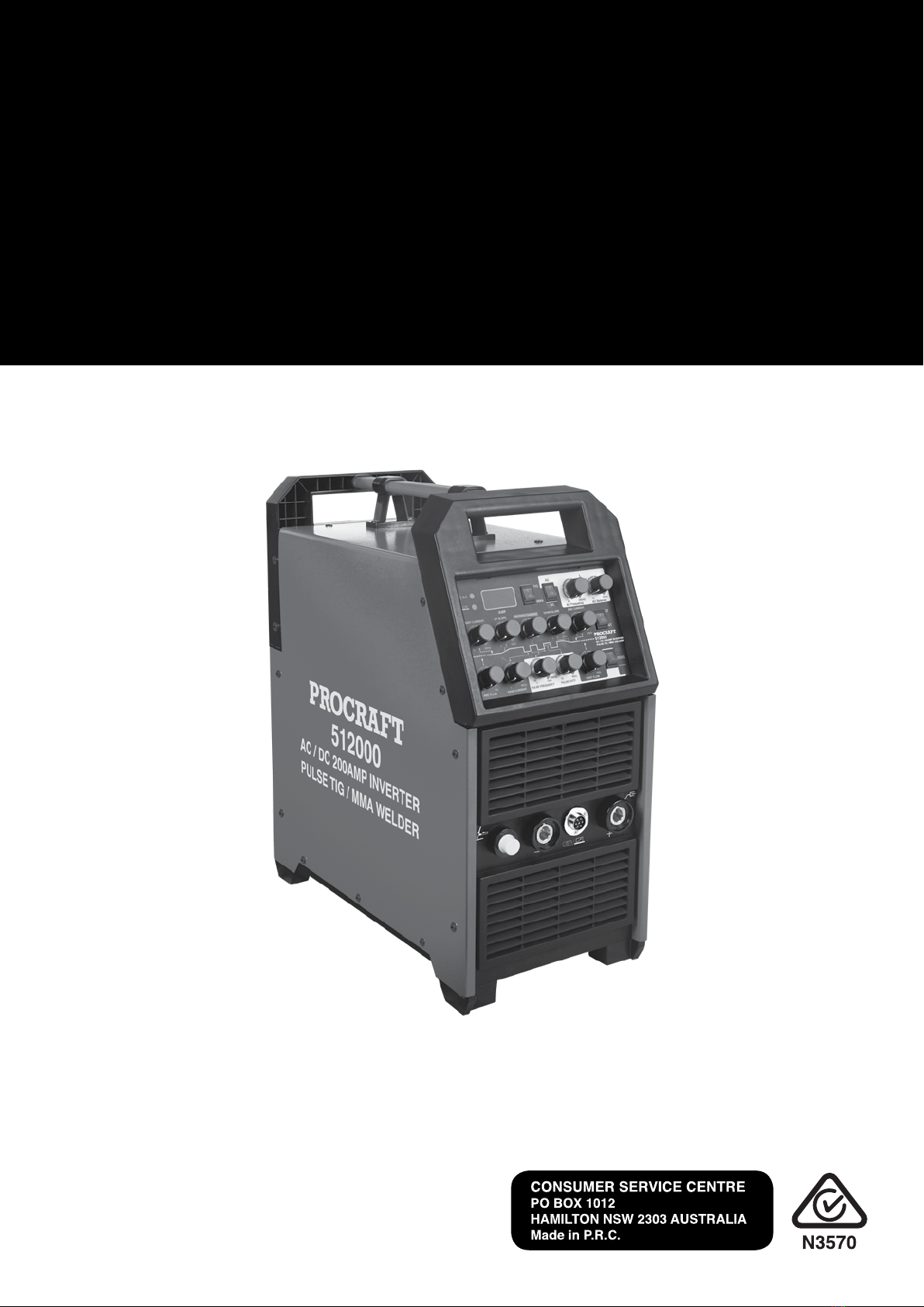
6. Welding with elementary electrodes (MMA methode)
6.1 Preparation of the device for work
Electrode holder
Earthclamp
Workpiece
Page 14
- 8 -
If the device is stored or transported in low temperatures, the device should be brought to the right
temperature before starting work !!!
The ends of the welding cables should be connected to the sockets (21) and (23) on the front panel, so
that the polarity of the electrode is on the electrode holder. The polarity of the welding cable
connection depends on the type of electrode used and is given on the electrode packaging. The clamp
of the return pipe should be securely attached to the welded material. Connect the device plug to the
115V/230V 60Hz mains socket. Switch on the device using the switch (25) on the back of the
welding machine.
6.2 Setting of welding parameters
The welding method switch (4) must be set to the MMA position. Turn the knob (11) to set the
desired welding current.
6.3 Arc initiation
Arc initiation during welding with the coated electrode consists in touching the electrode to the
welded material, short rubbing and detachment. In the case of arc initiation with electrodes, the
lagging of which forms a nonconductive slag after setting, it is necessary to pre-clean the top of the
electrode by repeated impact against a hard surface until metallic contact with the welded material.
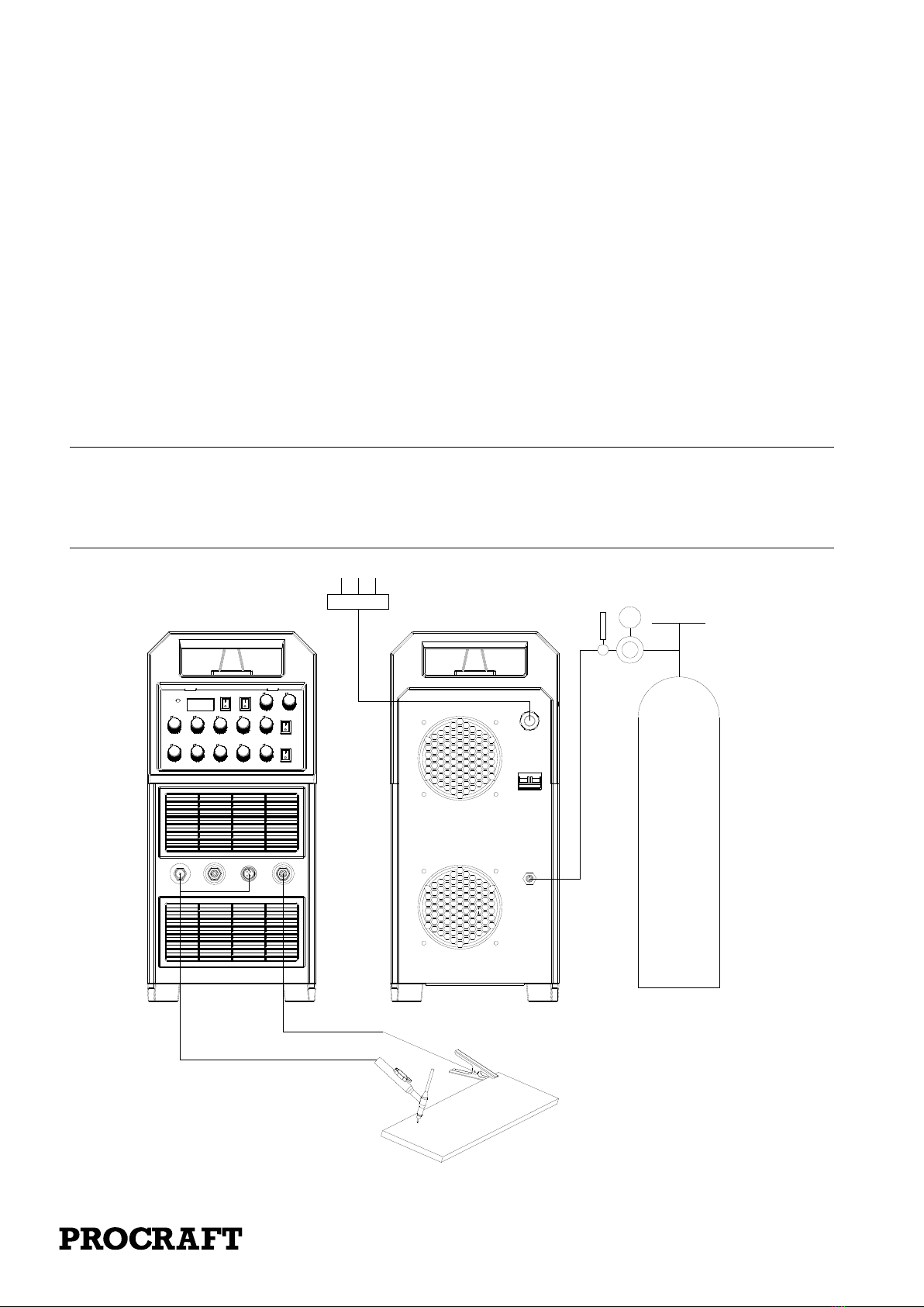
7. Welding with a non-combustible electrode in an inert gas shield (TIG
mothode)
groundclamp
workpiece
TIG weldingtorch
Gas
cylinder
Ar meter

Page 15
- 9 -
7.1. Connection of shielding gas
Secure the cylinder against tipping over. Unscrew the cylinder valve for a moment to remove any
contamination. Install the regulator on the cylinder. Connect the reducer hose to the welder by fitting
one end of the hose to the reducer connector and the other at the inlet connector (26) on the back of
the welding machine. Tighten the hose with the hose clamp. Open the cylinder and regulator valve.
7.2. Preparation of the device for work
If the device is stored or transported in low temperatures, the device should be brought to the right
temperature before starting work !!!
The TIG torch gas connector should be connected to the socket (20) and dinse plug should be
connected to the socket (21), the control plug of the torch should be carefully screwed to the control
socket (22), The gas pipe from the reducer should be led and secured to the gas connector (26) on the
back of the device. Connect the positive pole of the source with the material being welded using a
cable with a clamp. Connect the device plug to the 115/230V 60Hz mains socket. Switch on the
device using the switch (25) on the back of the welding machine.
7.3. Setting of welding parameters
7.3.1 Selecting the type of welding current
Set the welding current type with the switch (5). If you are going to use DC power, the switch should
be in the DC position and the AC should be AC.
7.3.2 Setting the welding current
The welding method switch (4) must be set to the TIG position. Turn the knob (13) to set the desired
start current value, turn the knob (12), the current rise time, the knob (11) the welding current value,
the knob (10) time of current descent, and the knob (9) the end current. In the case of alternating
current (AC) welding, the arc ignition is possible at a current of at least 20A.
7.3.3 Setting pulse parameters
Use the switch (19) to select the pulse rate range or non-pulse operation. In the case of pulse welding
with a knob (15) set the desired value of the base current, the knob (16) the pulse frequency, and the
knob (17) the duration of the current pulse
7.3.4 Setting of AC parameters
Turn the knob (7) to adjust the current balance. Turn the knob (6) to set the desired current frequency.
7.3.5 Setting gas flow parameters
Set the pre-flow time with the knob (14). Set the gas post-flow time using the knob (18).
7.3.6. Selecting the source control mode
Source control can be done in two-stroke or four-stroke mode. Select the source control mode using
the switch (8)
7.4. Arc initiation and welding process
The TIG 225 AC / DC pulse devices are equipped with an ionizer that allows contactless arc ignition.
To ignite the arc in the two-stroke mode, the electrode should be brought closer to the welded
material for a distance of 2 millimeters and press the button in the torch holder to activate the ionizer.
After correct arc initiation, carry out the welding with the button pressed. Releasing the button on the
handle causes the start of the current dropping phase and the end of the welding process.
In order to ignite the arc in the four-stroke mode, the electrode should be brought closer to the
material for 2 millimeters and press the button on the torch handle to activate the ionizer. After
correct arc ignition, the button can be released and the welding can be carried out with the button
released. To stop welding, press and release the button on the handle again.
Page 16
- 10 -
8. Welding with remote control
When the pedal switch is used to control, connect the 7-core aviation plug with the 7 socket.
The remote control green indictor(2) will be on, it is automatically recognized when you plug in,
adjust the knob(11) “Welding current”, it can set the maximum current when you press the foot
pedal to the maximum, the current display(3) will show the setting current. The digital display
shows the actual welding current when using foot pedal to control the welding.
WARNING !!
- During the welding of alternating current (AC) with low current values, the formation of oxides
on the surface of the tungsten electrode occurs. This can cause problems with arc ignition. In this
case, the electrode should be rubbed against the material being welded or otherwise mechanically
cleaned of the tip of the electrode from the oxide layer.
- Do not operate the button more than 2 mm from the welded material.
ground clamp
workpiece
TIGweldingtorch
Gas
cylinder
Ar meter

Page 17
- 11 -
- Do not touch the electrode while holding the button on the handle. The high voltage of the
ionizer and the unloaded voltage then occurring at the electrode can cause electric shock
9、Routine maintenance
Warning:
All the maintenance and repair jobs must be carried out when the power is cut-off
completely. Make sure the power plug is disconnected before opening the shell.
1Dust should be removed with dry and clean compressed air regularly. If the welder is used in a
heavily polluted environment with dense smoke and polluted air, dust must be removed from the
welder each month.
2The pressure of compressed air should be reasonable so that damage is not done to small elements
in the welder.
3Regularly check the connection of electric circuit in the welder and make sure circuit be
connected properly and joint is secured (especially inserted joint or element). If the cases of
rusting or loosening are found, the rust layer or oxidized film should be removed with abrasive
paper and then the joint should be connected again and tightened firmly.
4Entry of water or steam into the interior of the welder should be avoided. If this condition occurs,
the welder should undergo drying treatment. Then the welder is measured for insulation by a
megohm-meter (including the area between connecting points and the areas between the
connecting points and shell). Welding can go on only when evidence shows no abnormality.
5If the welder is not to be used for a long time, it should be replaced in the original package and
kept in a dry environment.

Page 18
- 12 -
10、Precautions before repairs
Warning
A haphazard experiment and imprudent repair may lead to expansion of fault area,
making formal repair more difficult. The exposed part of the welder in energization carries high voltage
that may lead to hazards and any direct or indirect touch with it will result in electric shock accident. In serious case
death may occur
If in the warranty period the user carries out an erroneous examination and repair of any fault in
the welding and cutting power without permission, the free maintenance warranty offered by the
supplier will be invalidated.
11、Precautions or preventive measures
1、Environment
1)Welding operation should be carried out in a relatively dry environment with air humidity usually
less than 90%.
2)Ambient temperature should be kept between -10C ~40C.
3)Welding in the sun or rain should be avoided and water or rainwater should never be seeped into
the welder interior.
4)Welding in the dusty area or under a corrosive gas environment should be avoided.
5)Gas protection welding operation in an environment with strong air flow should be avoided.
2、Essentials for safety
In this welder over-voltage, over-current and overheat protection circuits have been installed
beforehand. When the grid voltage, output current and machine temperature surpass the set
standards, the machine will stop automatically. But excessive use (for example, when the voltage
is too high) can still lead to the breakdown of the welder. So you have to pay attention to the
following items:
1)Good ventilation!
This machine is a small type welder. In operation a high working current flows in and natural
ventilation is unable to meet the welder’s requirement for cooling. So a fan is fitted to effectively
cool the welder to keep it work smoothly.
Operators should make sure that the vent is not covered or plugged, the distance of the welder
from its surrounding objects is not less than 0.3 m and good ventilation is kept all the time. All

Page 19
- 13 -
these are very important for better operation of the welder and longer service life of the welder.
2)No overload!
Operators should bear in mind that maximum permissible load current (relative to the selected
load duration factor) be observed at any time and welding current should never surpass the
maximum permissible load current.
Over-current will shorten the service life of the welder remarkably and even burn it down.
3)No over-voltage!
Power voltage is shown in the main performance parameter table. In general, the voltage
auto-compensation circuit in the welder will ensure the welding current remain within the
permissible range. If power voltage surpasses the permissible value, the welder will be broken
down. Operators should fully know this and adopt corresponding preventive measures.
4)Behind each welder there is a grounding screw with the grounding mark. Before operation the shell
of the welder should be grounded reliably by a cable wire with a sectional area bigger than 6mm2
so as to release static electricity or prevent any accident due to leakage.
5)If the welding machine exceeds the standard load duration factor in operation, it may probably go
into a protective state suddenly and stop work, which indicates it has exceeded the standard load
duration factor. Excessive heating triggers the temperature control switch and makes the welding
machine stop operation. Under such circumstances you needn’t turn off the power so that the
cooling fan may work continuously for cooling. When the temperature drops to the standard
range, welding may be restarted.
12、Troubles may be encountered in welding
Phenomena enumerated here may have something to do with the parts, gas, environmental factors
and power supply you use and efforts should be made in improving the environment to avoid
occurrence of such cases.
A、Black welding spot
——This shows the welding spot is oxidized without being protected effectively and you can
make the following inspection :
1. Make sure that the valve of argon cylinder has been opened with sufficient pressure. As a rule, if
the pressure within the cylinder is lower than 0.5MPa, then it is necessary to refill the cylinder.
2. Check if the argon flow-meter is turned on with sufficient flow. You can select different flow rates
in light of varying welding current, but too small flow may lead to inadequate gas stiffness and
thus failure to cover all the welded spots. We suggest argon flow should never be lower than
3l/min no matter how weak the current will be.
3. The easiest way to check gas delivery is to touch the nozzle of welding torch to see whether the

Page 20
- 14 -
gas passage of the welding torch is blocked.
4. Poor sealing of gas passage or lower gas purity will also give rise to welding quality trouble.
5. Strong air flow in the environment may also lead to deterioration of welding quality.
B、Difficulty in arc starting with easy arc breaking:
1. Make sure that the tungsten electrode in use is of good quality as discharge ability of inferior
tungsten electrode may fail the requirement;
2. Tungsten electrode without sharpening treatment is also unable to start arc and leads to unstable
arc.
C、Output current can’t reach the rated value:
Deviation of power voltage from the rated value will lead to unconformity of output current value
with the set value. When power voltage is lower than the rated value, maximum output current of the
welder may also be lower than the rated value.
D、Unstable current in the operation of the welder:
This may be attributed to the following factors:
1. Change in grid voltage;
2. Interference from the power grid or other power equipments.
E、:Severely burn of the tungsten needle
The duty cycle is adjusted too large, causing emission from the workpiece to the tungsten electron for
too long, resulting in severe heat of the tungsten needles.
F、The oxide film can’t be torn when welding aluminum:
1. the welding gear is selected wrong.
2. The duty cycle is adjusted too small;
3. The secondary inverter has field pipe damage.
G、The abnormal pilot lamp is on:
1、The light is on when the welder work abnormally, please turn off the power switch and then
reboot the machine, it can continue to use if it return to normal,
2、If the light is on repeatedly, please refer to the professional or the manufacturer for repair.
Table of contents
Other PROCRAFT Welding System manuals


