PROCRAFT 511464 User manual

MMA / TIG
MODELS 511464, 511465 & 511466
WELDING
SAVE THIS MANUAL
WARNING!
READ AND UNDERSTAND ALL INSTRUCTIONS
Failure to follow all instructions listed below may result
in electric shock, re, and/or serious injury.
SAVE THESE INSTRUCTIONS
Keep this manual for the safety warnings and precautions,
assembly, operating, inspection, maintenance and
cleaning procedures. Write the product’s serial number
in the back of the manual (or month and year of purchase
if product has no number). Keep this manual and the
receipt in a safe and dry place for future reference.
OPERATING INSTRUCTIONS
PROCRAFT

Page 2
IMPORTANT SAFETY INFORMATION
In this manual, on the labeling, and all other information
provided with this product:
This is the safety alert symbol. It is used to alert you to
potential personal injury hazards.
Obey all safety messages that follow this symbol to avoid
possible injury or death.
DANGER indicates a hazardous situation which, if not
avoided, will result in death or serious injury.
WARNING: WARNING indicates a hazardous situation
which, if not avoided, could result in death or serious injury.
CAUTION: CAUTION, used with the safety alert symbol,
indicates a hazardous situation which, if not avoided, could
result in minor or moderate injury.
NOTICE: NOTICE is used to address practices not related to
personal injury.
SAFETY WARNINGS AND PRECAUTIONS
WARNING: When using tool, basic safety precautions
should always be followed to reduce the risk of personal
injury and damage to equipment.
Read all instructions before using this tool!
WARNING!
READ AND UNDERSTAND ALL INSTRUCTIONS
Failure to follow all instructions listed below may result in
electric shock, fire, and/or serious injury.
SAVE THESE INSTRUCTIONS
Work Area Precautions
1. Keep your work area clean and well lit. Cluttered
benches and dark areas invite accidents.
2. Do not operate power tools in explosive atmospheres,
such as in the presence of flammable liquids, gases, or
dust. Power tools create sparks which may ignite the dust
or fumes.
3. Keep bystanders, children, and visitors away while
operating a power tool. Distractions can cause you to lose
control. Protect others in the work area from debris such as
chips and sparks. Provide barriers or shields as needed.
Electrical Safety
1. Grounded tools must be plugged into an outlet properly
installed and grounded in accordance with all codes and
ordinances. Never remove the grounding prong or modify
the plug in any way. Do not use any adapter plugs. Check
with a qualified electrician if you are in doubt whether the
outlet is properly grounded. If the tool should electrically
malfunction or break down, grounding provides a low
resistance path to carry electricity away from the user.
2. Double insulated tools are equipped with a polarized
plug (one blade is wider than the other). This plug will fit
in a polarized outlet only one way. If the plug does not fit
fully in the outlet, reverse the plug. If it still does not fit,
contact a qualified electrician to install a polarized outlet.
Do not change the plug in any way. Double insulation
eliminates the need for the three wire grounded power
cord and grounded power supply system..
3. Avoid body contact with grounded surfaces such as
pipes, radiators, ranges, and refrigerators. There is an
increased risk of electric shock if your body is grounded.
4. Do not expose power tools to rain or wet conditions.
Water entering a power tool will increase the risk of electric
shock.
5. Do not abuse the Power Cord. Never use the Power
Cord to carry the tool or pull the Plug from an outlet.
Keep the Power Cord away from heat, oil, sharp edges,
or moving parts. Replace damaged Power Cords
immediately. Damaged Power Cords increase the risk of
electric shock.
6. When operating a power tool outside, sue an outdoor
extension cord marker “W-A” or “W”. These extension
cords are rated for outdoor use, and reduce the risk of
electric shock.
PERSONAL SAFETY
1. Stay alert. Watch what you are doing, and use common
sense when operating a power tool. Do not use a power
tool while tired or under the influence of drugs, alcohol,
or medication. A moment of inattention while operating
power tools may result in serious personal injury.
2. Dress properly. Do not wear loose clothing or jewelry.
Contain long hair. Keep your hair, clothing, and gloves
away from moving parts. Loose clothes, jewelry, or long
hair can be caught in moving parts.
3. Avoid accidental staring. Be sure the Power Switch is
o before plugging in. Carrying power tools with your
finger on the Power Switch, or plugging in power tools with
the Power Switch on, invites accidents.
4. Remove adjusting keys or wrenches before turning the
power tool on. A wrench or a key that is left attached to
a rotating part of the power tool may result in personal
injury.
5. Do not overreach. Keep proper footing and balance
at all times. Proper footing and balance enables better
control of the power tool in unexpected situations.
Use safety equipment. Always wear eye protection.
Dust mask, non-skid safety shoes, hard hat, or hearing
protection must be used for appropriate conditions.
Tool Use and Care
1. Use clamps (not included) or other practical ways to
secure and support the workpiece to a stable platform.
Holding the work piece by hand to against your body is
unstable and may lead to loss of control.
2. Do not force the tool. Use the correct tool for your
application. The correct tool will do the job better and
safer at the rate for which it is designed.

Page 3
1. Do not use the power tool if the Power Switch does not
turn it on or o. Any tool that cannot be controlled with
the Power Switch is dangerous and must be replaced.
2. Disconnect the Power Cord Plug from the power source
before making any adjustments, changing accessories, or
storing the tool. Such preventive safety measures reduce
the risk of starting the tool accidentally.
3. Store idle tools out of reach of children and other
untrained persons. Tools are dangerous in the hands of
untrained users.
4. Maintain tools with care. Keep cutting tools maintained
and clean. Properly maintained tools are less likely to bind
and are easier to control. Do not use a damaged tool. Tag
damaged tools “Do not use” until repaired
Check for misalignment or binding of moving parts,
breakage of parts, and any other condition that may
aect the tool’s operation. If damaged, have the tool
serviced 1. before using. Many accidents are caused by
poorly maintained tools.
2. Use only accessories that are recommended by the
manufacturer for your model. Accessories that may be
suitable for one tool may become hazardous when used on
another tool.
SERVICE
1. Tool service must be performed only by qualified
repair personnel. Service or maintenance performed by
unqualified personnel could result in a risk of injury.
When servicing a tool, use only identical replacement parts.
Use of unauthorized parts or failure to follow maintenance
instructions may create a risk of electric shock or injury
SPECIFIC SAFETY RULES
1. Maintain labels and nameplates on the tool. These carry
important information. If unreadable or missing, contact
TOOLEX INDUSTRIAL for a replacement.
2. Always wear the approved safety impact eye goggles
and heavy work gloves when suing the tool. Using
personal safety devices reduce the risk for injury. Safety
impact eye goggles and heavy work gloves are available
from Harbor Freight Tools.
3. Maintain a safe working environment. Keep the work
area well lit. Make sure there is adequate surrounding
workspace. Always keep the work area free of obstructions,
grease, oil, trash, and other debris. Do not use a power tool
in areas near flammable chemicals, dusts, and vapors.
Do not use this product in a damp or wet location.
1. Avoid unintentional starting. Make sure you are prepared
to begin work before turning on the tool.
2. Never leave the tool unattended when it is plugged into
an electrical outlet. Turn o the tool, and unplug it from its
electrical outlet before leaving.
3. Always unplug the tool from its electrical outlet before
performing and inspection, maintenance, or cleaning
procedures.
4. Prevent eye injury and burns. Wearing and using the
approved personal safety clothing and safety devices
reduce the risk for injury.
a. Wear the approved safety impact eye goggles with a
welding helmet featuring at least a number 10 shade lens
rating.
b. Leather leggings, fire resistant shoes or boots should
be worn when using this product. Do not wear pants with
cus, shirts with open pockets, or any clothing that can
catch and hold molten metal or sparks.
c. Keep clothing free of grease, oil, solvents, or any
flammable substances. Wear dry, insulating gloves and
protective clothing.
d. Wear an approved head covering to protect the head
and neck. Use aprons, cape, sleeves, shoulder covers,
and bibs designed and approved for welding and cutting
procedures.
e. When welding/cutting overhead or in confined spaces,
wear flame resistant ear plugs or ear mus to keep sparks
out of ears.
1. Prevent accidental fires. Remove any combustible
material from the work area.
When possible, move the work to a. a location well
away from combustible; protect the combustibles with a
cover made of fire resistant material.
b. Remove or make safe all combustible materials for a
radius of 35 feet (10 meters) around the work area. Use a
fire resistant material to cover or block all open doorways,
windows, cracks, and other openings.
c. Enclose the work area with portable fire resistant
screens. Protect combustible walls, ceilings, floors, etc.,
from sparks and heat with fire resistant covers.
d. If working on a metal wall, ceiling, etc., prevent
ignition of combustibles on the other side by mobbing
the combustibles to a safe location. If relocation of
combustibles is not possible, designate someone to serve
as a fire watch, equipped with a fire extinguisher, during
the welding process and for at least one half hour after the
welding is completed.
a. Do not weld or cut on materials having a combustible
coating or combustible internal structure, as in walls or
ceilings, without an approved method for eliminating the
hazard.
b. Do not dispose of hot slag in containers holding
combustible materials. Keep a fire extinguisher nearby and
know how to use it.
After welding or cutting, make a thorough examination for
evidence of fire. Be aware that easily visible smoke or flame
may not be present for some time after the fire has started.
Do not weld or cut in atmospheres containing
a. Dangerously reactive or flammable gases, vapors, liquids,
and dust.
b. Provide adequate ventilation in work areas to prevent
accumulation of flammable gases, vapors, and dust. Do
not apply heat to a container that has held an unknown
substance or a combustible material whose contents, when
heated, can produce flammable or explosive vapors. Clean
and purge containers before applying heat. Vent closed
containers, including castings, before preheating, welding,
or cutting.

Page 4
WARNING
INHALATION HAZARD: Welding and Plasma
Cutting Produce
TOXIC FUMES.
Exposure to welding or cutting exhaust fumes can increase
the risk of developing certain cancers, such as cancer of
the larynx and lung cancer. Also, some diseases that may
be linked to exposure to welding or plasma cutting exhaust
fumes are:
a. Early onset of Parkinson’s Disease
b. Heart disease
c. Ulcers
d. Damage to the reproductive organs
e. Inflammation of the small intestine or stomach
f. Kidney damage
g. Respiratory diseases such as emphysema, bronchitis, or
pneumonia
Use natural or forced air ventilation and wear a respirator
approved by NIOSH to protect against the fumes produced
to reduce the risk of developing the above illnesses.
Avoid overexposure to fumes and gases. Always keep your
head out of the fumes. Do not breathe the fumes.
1. Use enough ventilation or exhaust, or both, to keep
fumes and gases from your breathing zone and general
area.
a. Where ventilation is questionable, have a qualified
technician take an air sampling to determine the need for
corrective measures. Use mechanical ventilation to improve
air quality. If engineering controls are not feasible, use an
approved respirator.
b. Work in a confined area only if it is well ventilated, or
while wearing an air-supplied respirator.
c. Follow OSHA guidelines for Permissible Exposure Limits
(PEL’s) for various fumes and gases.
d. Follow the American Conference of Governmental
Industrial Hygienists recommendations for Threshold Limit
Values (TLV’s) for fumes and gases.
e. Have a recognized specialist in Industrial Hygiene or
Environmental Services check the operation and air quality
and make recommendations for the specific welding or
cutting situation.
2. Always keep hoses away from welding/cutting spot.
Examine all hoses and cables for cuts, burns, or worn areas
before each use. If any damaged areas are found, replace
the hoses or cables immediately.
3. Read and understand all instructions and safety
precautions as outlined in the manufacturer’s Manual for
the material you will weld or cut.
1. Proper cylinder care. Secure cylinders to a cart, wall, or
post, to prevent them from falling. All cylinders should be
used and stored in an upright position. Never drop or strike
a cylinder. Do not use cylinders that have been dented.
Cylinder caps should be used when moving or storing
cylinders. Empty cylinders should be kept in specified areas
and clearly marked “empty.”
2. Never use oil or grease on any inlet connector, outlet
connector, or cylinder valves.
3. Use only supplied Torch on this Inverter Air Plasma
Cutter. Using components from other systems may cause
personal injury and damage components within.
People with pacemakers should consult their physician(s)
before using 1. this product. Electromagnetic fields
in close proximity to a heart pacemaker could cause
interference to, or failure of the pacemaker.
2. USE PROPER EXTENSION CORD.
Make sure your extension cord is in good condition.
When using an extension cord, be sure to use one heavy
enough to carry the current your product will draw. An
undersized cord will cause a drop in line voltage resulting
in loss of power and overheating. We recommend that
a 15amp extension cord be used with the 1.5mm2 cable.
The following Toolex Industrial Extension Leads would be
suitable 594530 10 metre, 594531 20 metre & 594532 30
metre.

Page 5
About the machine
MMA series welding machine is a rectifier adopting the most advanced inverter
technology.
The development of inverter gas-shielded welding equipment profits from the
development of the inverter power supply theory and components. Inverter
gas-shielded welding power source utilizes high-power component IGBT to transfer
50/60HZ frequency up to 50KHZ, then reduce the voltage and commutate, and output
high-power voltage via PWM technology. Because of the great reduce of the main
transformer’s weight and volume; the efficiency increases by 30%. The appearance of
inverter welding equipment is considered to be a revolution for welding industry.
MMA series welding power source can offer stronger, more concentrated and
more stable arc. When stick and work piece get short, its response will be quicker. It
means that it is easier to design into welding machine with different dynamic
characteristics, and it even can be adjusted for specialty to make arc softer or harder.
MMA welding machine has the following characteristics: effective, power saving,
compact, stable arc, good welding pool, high no-load voltage, good capacity of
force compensation and multi-use. It can weld stainless steel, alloy steel, carbon steel,
copper and other color metal. It can apply to electrode of different specifications and
materials, including acidity, alkalescence, and fibre. It can apply in high altitude, the
open air and inside and outside decoration. Compared with the same products of home
and abroad, it is compact in volume, light in weight, easy to install and operate.
Thanks for purchasing product and hope for your precious advice. We will dedicate to
produce the best products and offer the best service.
CAUTION!
The machine is mainly used in industry. It will produce radio wave, so the
worker should make fully preparation for protection.
PARAMETERS

Page 6
511464
140AMP
511465
200AMP
511466
180AMP
240V
Dimensions
Eciency
Duty Cycle (%)
Rated Input
Voltage (V)
Output Current
(A)
Rated Input
Current (A)
Frequency (hz)
Power Voltage (V)
MODELS
Parameters
Weight (kg)
Housing Protection
Grade
345 x 230 x 235 450 x 300 x 305 330 x 290 x 250
22.1
24.4
20 - 140 20 - 180 20 - 200
50/60
50/6050/60
60% @ 110A 60% @ 150A 60% @ 170A
26 26
3
IP21
85
8585
IP21
IP21
6.8 7.5
25 32
240V 240V
Page 7
equipment. When power voltage moves between±15% of rated voltage, it still can
work normally.
When use long cable, in order to prevent voltage form going down, bigger section
cable is suggested. If cable is too long, it may affect the performance of the power
system. So we suggest you to use configured length.
1、Make sure intake of the machine not blocked or covered, lest cooling system
could not work.
2. Use inducting cable whose section is not less than 6 mm² to connect the
housing to the ground. The way is from the ground-connecting screw at the back to
the earth device.
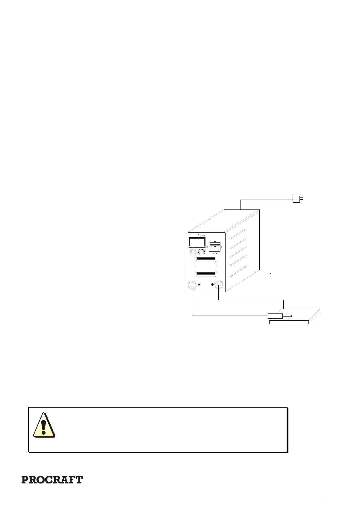
3. Correctly connect the arc torch or holder according to the sketch. Make sure the cable,
holder and fastening plug have been connected with the ground. Put the fastening plug into
the fastening socket at the “-“polarity and fasten it clockwise.
4. Put the fastening plug of the cable to fastening socket of “+” polarity at the front
panel, fasten it clockwise, and the earth clamp at
the other terminal clamps the work piece.
5. Please pay attention to the connecting
polarity, DC welding machine has two
connecting ways: positive connection and
negative connection. Positive connection:
holder connects with “-“ polarity, while work
piece with the “+”polarity. Negative
connection: work piece with the “-“ polarity,
holder with the “+” polarity. Choose suitable
way according to working demands. If
unsuitable choice, it will cause unstable arc,
more spatters and conglutination. If such
problems occur, please change the polarity of the fastening plug.
6.According to input voltage grade, connect power cable with power supply box of
relevant voltage grade. Make sure so mistake and make sure the voltage difference
among permission range. After the above job, installment is finished and welding is
available.
If distance of work piece and machine is too far (50 - 100m), and the cables
(torch cable and earth cable) are too long, please choose cable of bigger
section to minimize the reduction of the voltage.
1PH 240V
Earth
Electrode Holder
Electrode
Lead '-'
Earth Lead +
Power Supply Cord

Page 8
511464
Panel Instruction:
511465
Panel Instruction:
511466
Panel Instruction:
MODEL: 511465 INVERTER MMA / TIG 220i

Page 9
DUTY CYCLE
Duty Cycle is the equipment specifications which defines the
number of minutes within a 10 minute period that a piece of
equipment can safely operate.
ECO (MOSFET) ARC machines have a 35% duty cycle at
maximum welding output, which means that it continuously
operates for 3.5 minutes at maximum output during a 10
minute period.
CAUTION: Failure to observe the duty cycle limitations of
this TIG MACHINE can easily damage this equipment, and
will void warranty.
UNPACKING
When unpacking, checks to make sure the following parts
are included.
Inverter welding machine with Ground cable with Clamp
MMA welding cable with clamp If any parts are missing or
broken, please call EACO ELECTRIC at the number on the
cover of this manual.
Preparing Your Work Area
1. You must have a sturdy work table that is open below the
area you are welding. Molten slag will be blown through the
work metal, and must be able to fall away freely
2. Your work table must allow the work metal to be firmly
clamped to prevent it accidentally falling or moving.
The floor and surrounding area of your work site must not
be flammable. A clean cement floor is recommended.
1. The cutting process will eject molten metal slag onto the
floor, and it will scatter for 8-10 feet or more in any direction.
Have an adequate fire extinguisher available if needed.
ASSEMBLY
Grounding the tool
Ground screw (1)
1. Attach a ground wire (not supplied) to the screw in the
lower the back of the machine. Connect the other end of the
wire to an appropriate ground, such as a steel workbench,
steel biding member or grounding electrode.
Connector Instruction
MMA Welding cable and TIG torch socket (1)
Ground socket (1)
1. Ground socket: Plug ground cable to this socket.
2. MMA Welding cable socket: Connect MMA Welding cable
or the TIG cable plug to this socket
INSTALLATION
1. Connect welding tongs with output stud terminal (+)
2. Connect ground clamp with output terminal (-)
3. Connect the protection grounding cable.
4. Turn on the distributing box and the switch on the power
source on the front panel.
5. Start welding.
6. Finish welding.
7. Turn o the switch on front.
8. Turn o the switch of distributing box
OPERATION
Note: Before beginning, please read and understand all
the safety precautions staring on page 1 and especially the
section “Specific Safety Rules” starting on page 3.
Put the metal to be welded on the metal weeding-cutting
table. Ensure the metals to
1. be welded are clean, so good welding eciency can be
promised.
2. Place the MMA welding unit no closer than six feet from
the work piece to be welded
3. Connect the MMA torch control, Twist to lock in place.
4. Plug in the Grounding Cable into the Ground Connector
on the lower left of the unit front. Twist to lock.
5. Place the metal portion of the welding rod inside the jaws
of the Electrode Clamp. Welding rod types vary for welding
dierent metals.
6. Hold the MMA torch and orient yourself to one side of
the area to be welded, and move the Welding Helmet Face
Shield (not included, see page 4 item 7) over your eyes.
7. Hold the MMA welding rod down and tilt the rod forward.
8. Stroke the work piece lightly to ignite the arc. Does not
strike like a match? Never tap the electrode wire to ignite the
arc; it will damage the rod.
9. When the arc ignites, tilt the electrode forward and hold it
near the work piece.
If too much current is drawn from the welder; the Thermal
Overload protector will 1. activate, the Overload indicator or
will light, and the welder will turn o until it cools down. It
will automatically reset.
Welding current
Welding current level is determined by the size of electrode
- the normal operating range and current are recommended
in the manual. Typical operating ranges for a selection of
electrode sizes are illustrated in the table. As a rule of thumb
when selecting a suitable current level, an electrode will
require about 40A per millimeter (diameter). Therefore, the
preferred current level for a 4mm diameter electrode would
be 160A, but the acceptable operating range is 140 to 180A.
MMA Welding Tips
Thickness <1 2 3 4~5 6~12 >13
Rod dia. <1.5 2 3.2 3.2~4 4~5 5~6
Current (A) 20~40 40~50 90~110 90~130 160~250 250~400
DANGER! To prevent serious injury and death: If the
operator is not holding the Torch, it must be sitting on a
non-conductive, nonflammable surface.
A: Connect the welding torch with output stud terminal
“+” and work piece with terminal “+” if using alkaline
welding rod.
B: Suggesting fixing welding current according to the
following expressions:
Welding current = (20+6D) ×D
“D” refers to the diameter of welding rod(mm)
* Note: If some other troubles occur when using our welding
machine, please contact with the agency of our company.

Page 10
MAINTENANCE
WARNING! Make sure the Power Switch of the WELDER is in it’s “OFF” position and that the tool is unplugged from the
electrical outlet before performing any inspection, maintenance, or cleaning procedures.
1. Before each use, inspect the general condition of the Welder. Check for loose cable connections, misalignment or
binding of the fan, cracked or broken parts, damaged electrical wiring, and any other condition that may aect its safe
operation. If abnormal noise or vibration occurs, have the problem corrected before further use. Do not use damaged
equipment.
2. Periodically recheck all nuts, bolts, and screws for tightness.
3. Periodically blow the dust from the cooling vents with compressed air.
4. Verify that the cooling fan is operational before welding.
5. If the unit repeatedly shuts down from thermal overload, stop all use. Have the welder inspected and repaired by a
qualified service technician.
6. Store the welder and accessories in a clean and dry location.
7. Periodically disassemble and clean the Torch Head components with steel wool. Replace burnt, cracked, distorted, or
coated components, Refer to the assembly drawing on page 11.
1. To gain access to the internal components of the unit, remove screws from Main Body Cover. The home user is strongly
advised not to remove the tool covers and not to attempt any electronic repairs. Any repairs must be completed by a
qualified technician. Opening the tool will void any warranties, and may result in damage to equipment or possible per-
sonal injury. Don’t do it.
2. On a daily basis check for any of the following problems: If any are found, take the tool to a qualified repair technician.
a. Abnormal vibration, sound or smell.
b. Abnormal heating at any cable connection.
c. Then fan does not work properly.
d. Any switch or control does not work properly.
e. Any damage to cables.
Storage: For your safety, please pile up the machines for less than three tiers, and fix them up with ropes.
6) Surrounding requirements:
• Dry and clean in-door place. Do not use in the rain.
• Surrounding temperature: -10°C~40°C
• Relative humidity: ≤50% at 40°C; ≤90% at 20°C
Keep the distance between the
• Surrounding temperature: -10°C~40°C
• Relative humidity: ≤50% at 40°C;
≤90% at 20°C
• Altitude level < 1000 m
Keep the distance between the
• Altitude level < 1000 m
Keep the distance between the Ø machine and walls above 20cm
• Keep the distance between two machines above 30cm
Protect the machine and gas cylinders from shakes and Ø shocks.
• Store machine in ventilation place and keep away from rain, snow and any caustic material.

Page 11
MANUAL METAL ARC (MMA) WELDING
Shielded metal arc welding (SMAW), also known as manual metal arc (MMA) welding, and flux-shielded arc welding
or informally as stick welding, is a manual arc welding process that uses a consumable electrode coated in flux to lay
the weld. An electric current, in the form of either alternating current or direct current from a welding power supply, is
used to form an electric arc between the electrode and the metals to be joined. As the weld is laid, the flux coating of the
electrode disintegrates, giving o vapors that serve as a shielding gas and providing a layer of slag, both of which protect
the weld area from atmospheric contamination.
Because of the versatility of the process and the simplicity of its equipment and operation, shielded metal arc welding
is one of the world’s most popular welding processes. It dominates other welding processes in the maintenance and
repair industry, and though flux-cored arc welding is growing in popularity, SMAW continues to be used extensively in
the construction of steel structures and in industrial fabrication. The process is used primarily to weld iron and steels
(including stainless steel) but aluminum, nickel and copper alloys can also be welded with this method.
To strike the electric arc, the electrode is brought into contact with the work piece by a very light touch with the
electrode to the base metal then is pulled back slightly. This initiates the arc and thus the melting of the work piece and
the consumable electrode, and causes droplets of the electrode to be passed from the electrode to the weld pool. As
the electrode melts, the flux covering disintegrates, giving o shielding gases that protect the weld area from oxygen
and other atmospheric gases. In addition, the flux provides molten slag which covers the filler metal as it travels from
the electrode to the weld pool. Once part of the weld pool, the slag floats to the surface and protects the weld from
contamination as it solidifies. Once hardened, it must be chipped away to reveal the finished weld. As welding progresses
and the electrode melts, the welder must periodically stop welding to remove the remaining electrode stub and insert a
new electrode into the electrode holder. This activity, combined with chipping away the slag, reduce the amount of time
that the welder can spend laying the weld, making SMAW one of the least ecient welding processes. In general, the
operator factor, or the percentage of operator’s time spent laying weld, is approximately 25%.
The actual welding technique utilized depends on the electrode, the composition of the work piece, and the position
of the joint being welded. The choice of electrode and welding position also determine the welding speed. Flat welds
require the least operator skill, and can be done with electrodes that melt quickly but solidify slowly. This permits higher
welding speeds. Sloped, vertical or upside-down welding requires more operator skill, and often necessitates the use of
an electrode that solidifies quickly to prevent the molten metal from flowing out of the weld pool. However, this generally
means that the electrode melts less quickly, thus increasing the time required to lay the weld.

Page 12
PROCRAFT WARRANTY INFORMATION
Every PROCRAFT welder has been thoroughly inspected and tested before leaving the factory. In addition to any statu-
tory regulations, TOOLEX warrants all of its products against faulty workmanship and faulty material for a twelve (12)
month period from the date of purchase and undertakes, once inspected, to repair or replace, free of charge each product
or part thereof that are faulty, on condition that:
The complete product is returned to TOOLEX or one of its Authorised Service Centres, in person of freight pre-paid by the
consumer, and the tool is found on examination, to be faulty from a manufacturing defect.
The product or relevant spare parts have not been misused, neglected, or been damaged by in an accident or the repairs
are required due to normal wear and tear.
Our goods come with guarantees that cannot be excluded under the Australian Consumer Law.
You are entitled to a replacement or refund for major failure and for compensation for any reasonable foreseeable loss or
damage. You are also entitled to have the goods repaired or replaced if the goods fail to be of acceptable quality and the
failure does not amount to a major failure.
PLEASE SUPPLY A COPY OF YOUR TAX INVOICE FOR YOUR WARRANTY!
ABNORMAL PHENOMENA FAULT CAUSE EXCLUDING WAY
Fan doesn’t work when turn on the
machine, no output display
Lacks power phase Check power supply
Line broken Check connection
Fuse (10A) is broken Change fuse
Gas switch on back panel is broken
when in normal working
IGBT module, rectifier bridge, output diode, or
other components may damaged
Check-up and replace
Drive board damaged Check-up and replace
Short circuit between line Check-up and replace
Welding current is unstable Lacks phase Check-up power supply
Potentiometer may damaged Check-up and replace
Main PCB may damaged Check-up and replace
Welding current can’t be adjusted Current adjust potent -meter may damaged Check-up and replace
Main control board may damaged Check-up and replace
Switch on front panel may damaged Check-up and replace
Over heat indicator will light
Overabundance used Use welding
machine according to its rated duty
cycle.
Unsteady electric arc or unsatisfied welding
eect
The polarity is wrongly
connected
Output or input circuit is not well connected
somewhere
Examine and repair to
have it firmly connected
Welding current does not match for the diameter
of welding rod
Check and correct it
Unsteady electric arc or unsatisfied
welding eect
The polarity is wrongly connected Check and correct it
Output or input circuit is not well connected
somewhere
Examine and repair to
have it firmly connected.
Welding current does not match for the diameter
of welding rod
Check and correct it
511464, 511465 & 511466
TROUBLESHOOTING
IMPORTANT!
Be CERTAIN to shut o the welder and disconnect it from power and
air before adjusting, cleaning, or repairing the unit. A technician should
discharge all capacitors before performing and internal procedures.
Page 13
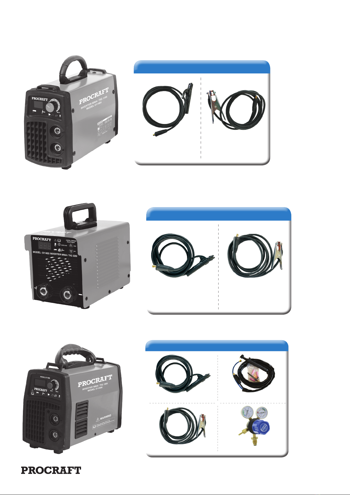
INCLUDED STANDARD ACCESSORIES
INCLUDED STANDARD ACCESSORIES
4m Cable & Electrode
Holder (500890)
4m Cable &
Earth Clamp (500892)
511464: 140i MMA / TIG
511465: 220i MMA / TIG
511466: 180i MMA / TIG
INCLUDED STANDARD ACCESSORIES
4m Cable &
Electrode Holder
(500891)
4m Cable &
Earth Clamp
(500893)
INCLUDED STANDARD ACCESSORIES
4m Cable & Electrode Holder (500891)
4m Cable & Earth Clamp (500893) Argon Regulator
TIG Torch 4m Long (500887)
This manual suits for next models
2
Table of contents
Other PROCRAFT Welding System manuals


Popular Welding System manuals by other brands

Sealey
Sealey SUPERMIG250 Instructions for use

Castolin
Castolin 2000 FLEX Instructions for use and maintenance

Lincoln Electric
Lincoln Electric INVERTEC V320-T AC/DC Operator's manual

Murex
Murex Tradesmig 171 instruction manual

ESAB
ESAB EMP 285ic 1ph instruction manual

Trumpf
Trumpf TruArc Weld 1000 Operator's manual


Lincoln
Lincoln LN-25 PRO Operator's manual

Lincoln Electric
Lincoln Electric PRINCE IM818 Operator's manual

Würth
Würth MIG/MAG 250 instructions

Miller Electric
Miller Electric IH owner's manual

PRO WELD INTERNATIONAL
PRO WELD INTERNATIONAL ARC 800 Operation/maitenance manual

Miller Electric
Miller Electric STH 160 owner's manual