Produal HLS 44-SER User manual

USER GUIDE
HLS 44-SER
V1.1.0 (22.04.2014)
1 (6)
Produal Oy Keltakalliontie 18, 48770 Kotka FINLAND Tel: +358 10 219 9100 / Fax: +358 5 230 9210 [email protected]i www.produal.com
Information is subject to change without prior notice.
Commissioning tool HLS 44-SER
HLS 44-SER is a tool for commissioning HLS 44 and HLS 44-V controllers. By using this tool the commissioning is fast and you may rely on
that the settings are as planned.
It is useful to plan and program the settings to the tool with care in advance. After that, you can load the settings to the controllers in office or
on the installation site during commissioning.
This user guide is for the commissioning tool software version 1.1.0 or newer. The tool software version shows on the tool display when the
power is switched on.
PROFILES
HLS 44-SER commissioning tool contains fixed factory settings (PRSET 1) for HLS 44 and HLS 44-V, memory slots for 5 user defined
solutions (SET 1...5) and 4 pre-programmed application profiles (SET 6...9). All parameters of SET 1...9 can be changed for a best possible
room control solution. For more information see the instructions of HLS44 and HLS 44-V.
Pre-programmed applications (SET 6…9) are the following:
SET 6 Heating by radiator and cooling by beam
SET 7 Heating and cooling by a fan coil unit
SET 8 Heating by radiator and cooling by VAV and beam (VAV control based on CO2concentration)
SET 9 Heating by radiator and cooling by beam (dampers and lights ON/OFF by PIR detection; HLS 44-V)
GETTING STARTED
1. Remove the controller cover.
2. Connect the commissioning tool cable to the controller programming terminal.
A. Commissioning tool cable
NOTE: Connecting the tool to the programming terminal will disconnect the controller from the Modbus communication.
3. Connect the supply voltage either to the commissioning tool or the controller.
IMPORTANT: Do not connect the supply voltage to both devices.
4. Check that the software version numbers are compatible.
The software versions are shown on the displays when you switch on the power. See the compatible software versions from the
following table.
HLS 44-SER
software version Compatible HLS 44 and
HLS 44-V software versions
1.0.0 1.0.0 -> 1.0.2
1.1.0 1.1.0 -> 1.1.2
1.1.3 1.1.3
1.1.4 1.1.4 -> 1.1.7
1.1.8 1.1.4 -> 1.1.9
USER GUIDE
HLS 44-SER
2 (6)
Produal Oy Keltakalliontie 18, 48770 Kotka FINLAND Tel: +358 10 219 9100 / Fax: +358 5 230 9210 [email protected]i www.produal.com
Information is subject to change without prior notice.
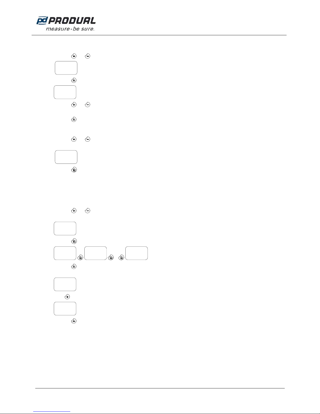
LOADING PARAMETERS TO THE CONTROLLER
1. Press the and buttons to select the profile (SET 1…9 or PRSET 1) which you want to load to the controller.
2. Press the button to enter the Modbus address setting view.
3. Press the and buttons to select the Modbus address for the controller.
The Modbus address number steps automatically forward number by number, when multiple controllers are programmed.
4. Press the button to load the parameters to the controller.
SETTING THE PARAMETERS IN THE COMMISSIONING TOOL
1. Press the and buttons to select the profile (SET 1…9) in which you want to store the parameters.
NOTE: The selected profile will be overwritten with the new parameters. You cannot recover the overwritten profiles.
2. Press the button.
3. Make the wanted adjustments in the menu.
See the detailed parameter setting instructions from the HLS 44 or HLS 44-V user guide.
4. Load the parameters to the controller.
LOADING PARAMETERS FROM THE CONTROLLER TO THE COMMISSIONING TOOL
1. Press the and buttons to select the profile (SET 1…9) in which you want to load the parameters.
NOTE: The selected profile will be overwritten with the new parameters. You cannot recover the overwritten profiles.
2. Press the button until you reach the parameter loading menu.
…
3. Press the button.
Verification message appears on the display.
4. Press button to change the verification message to “Yes” status.
5. Press the button to load the parameters from the controller to the commissioning tool memory.
8
ID=
1
SET
1
SET
----
COMM
1
SET
1
SET
Yes
Sure?
No
Sure?
----
LOAD

USER GUIDE
HLS 44-SER
3 (6)
Produal Oy Keltakalliontie 18, 48770 Kotka FINLAND Tel: +358 10 219 9100 / Fax: +358 5 230 9210 [email protected]i www.produal.com
Information is subject to change without prior notice.
MODBUS REGISTERS OF THE SET 6…9 PROFILES
SET 6: Heating with radiator and cooling with beam
Register Parameter Description Value Range Default Comments
COILS
1 Cooling PWM overdrive enable (A1) Off=0, On=1 Off - On 0 No modbus overdrives
2 Cooling 0-10V overdrive enable (Y3) Off=0, On=1 Off - On 0 No modbus overdrives
3 Heating PWM overdrive enable (A2) Off=0, On=1 Off - On 0 No modbus overdrives
4 Heating 0-10V overdrive enable (Y4) Off=0, On=1 Off - On 0 No modbus overdrives
5 VAV overdrive enable (Y1) Off=0, On=1 Off - On 0 No modbus overdrives
6 FAN overdrive enable (Y2) Off=0, On=1 Off - On 0 No modbus overdrives
7 On/Off damper overdrive enable (B1) Off=0, On=1 Off - On 0 No modbus overdrives
8 Light control overdrive enable (B2) Off=0, On=1 Off - On 0 No modbus overdrives
9 Overdrive On/off damper by modbus (B1) Off=0, On=1 Off - On 0 No modbus overdrives
10 Overdrive Light control by modbus (B2) Off=0, On=1 Off - On 0 No modbus overdrives
11 SERVICE ALARM RESET Off=0, On=1 Off - On 0
12 Cooling disabled Off=0, On=1 Off - On 0 Cooling working
13 Heating disabled Off=0, On=1 Off - On 0 Heating working
14 NIGHT MODE Off=0, On=1 Off - On 0 The device is allways in day mode
15 Cooling output mode (DIR/REV) Off=0, On=1 Off - On 0 Direct output mode
16 Heating output mode (DIR/REV) Off=0, On=1 Off - On 0 Direct output mode
17 Cooling stages (1st/2st) Off=0, On=1 Off - On 0 1 stage cooling, chilled beam
18 Sequence of cooling stages (A-st/V-st) Off=0, On=1 Off - On 0 No affect on this process
19 Fan ramp with motor ramp Off=0, On=1 Off - On 1 No affect on this process
20 Night operation mode (DZ/FG) Off=0, On=1 Off - On 0 No affect, if the device is allways in day mode, see Coil 14
21 Night to day setpoint transition Off=0, On=1 Off - On 0 No affect, if the device is allways in day mode, see Coil 14
22 Jam function Off=0, On=1 Off - On 0 the jum fuction is not activated
23 Fan type (3coil/CE) Off=0, On=1 Off - On 0 No affect on this process
24 Fan speed 3 disabled Off=0, On=1 Off - On 0 No affect on this process
25 Fan night to day transition Off=0, On=1 Off - On 0 No affect, if the device is allways in day mode, see Coil 14
26 VAV for heating Off=0, On=1 Off - On 0 No affect on this process, the VAV function is not used
27 Display TE/SP Off=0, On=1 Off - On 0 The display shows the room temperature (not the setpoint)
28 DI2 operation direction Off=0, On=1 Off - On 0 DI2 is not used. No affect on this process
29 Cooling on/off thermostat (off = P/PI) Off=0, On=1 Off - On 0 P/PI mode for cooling
30 Heating on/off thermostat (off = P/PI) Off=0, On=1 Off - On 0 P/PI mode for heating
31 Y1 for cooling (off = VAV) Off=0, On=1 Off - On 0 Y1 is not connected ... No influence
32 Y2 for heating (off = FAN) Off=0, On=1 Off - On 0 Y1 is not connected ... No influence
HOLDING REGISTERS
40001FAN Speed by Modbus 0 … 4 0 - 1 - 2 - 3 - 4 0 No affect on this process
40002Setpoint by Modbus 80 … 500 8,0 … 50,0 °C 210 Temperature setpoint from modbus 21°C
40003Overdrive Cooling PWM by modbus (A1) 0 … 1000 0,00 … 100,0% 0 No modbus overdrives chosen... The value has no affect (see coils 1 ... 10)
40004Overdrive Cooling 0...10V by modbus (Y3) 0…1000 0 …10.00 V 0 No modbus overdrives chosen... The value has no affect (see coils 1 ... 10)
40005Overdrive Heating PWM by modbus (A2) 0 … 1000 0,00 … 100,0% 0 No modbus overdrives chosen... The value has no affect (see coils 1 ... 10)
40006Overdrive Heating 0...10V by modbus (Y4) 0…1000 0 …10.00 V 0 No modbus overdrives chosen... The value has no affect (see coils 1 ... 10)
40007Overdrive VAV by modbus (Y1) 0…1000 0 …10.00 V 0 No modbus overdrives chosen... The value has no affect (see coils 1 ... 10)
40008Overdrive FAN by modbus (Y2) 0…1000 0 …10.00 V 0 No modbus overdrives chosen... The value has no affect (see coils 1 ... 10)
40009DI2 Not used, ext T, door/window, condensation 0 … 3 0 … 3 0 DI2 is not used in this process
40010 Temperature sensor adjustment -30 … 30 -3,0 … 3,0 °C 0 Internal sensor has its factory calibration
40011 Center of user setpoint 180 … 260 18,0 … 26,0 °C 210 Center of the user setpoint 21°C
40012 User setpoint limits 0 … 160 0,0 … 16,0 °C 30 End user can change the setpoint +/- 3 °C from the point above
40013 Control mode 0 … 1 P/PI 1 Control mode PI
40014 Dead zone 0 … 30 0,0 … 3,0 °C 2 Dead zone 2,0 °C
40015 Setpoint relation to Dz 0 … 100 0 … 100% 50 Setpoint is in the center of the dead zone
40016 Proportional band 10 … 320 1,0 … 32,0 °C 20 Proportional band 2,0 °C
40017 Integral time 50 … 5000 50 … 5000s 300 Ti = 300 seconds
40018 Fresh air control: 0:CO2 (T), 1:PIR (T), 2: CO2, 3:PIR 0 … 3 0 … 3 0 No influence because VAV is not used in this process
40019 Dead zone night mode 0 … 100 0,0 … 10,0 °C 60 No affect, if the device is allways in day mode, see Coil 14
40020 FG Thermostat setpoint 80 … 500 8,0 … 50,0 °C 170 No affect, if the device is allways in day mode, see Coil 14 and Coil 20
40021 DI1 mode selection: 0= not used, 1= day night by ext
contact 0 … 1 0 … 1 0 DI1 is not used to controll day/night mode
40022 DI1 operation Direction 0 … 1 0 … 1 0 DI1 not used ... No influence
40023 DI1 delay passive to active 0 … 60 0 … 60min 0 DI1 not used ... No influence
40024 DI1 delay active to passive 0 … 60 0 … 60min 5 DI1 not used ... No influence
40025 “man in house”-button, day extension period 1 … 480 1 … 480min 120 No affect, if the device is allways in day mode, see Coil 14
40026 DI1 boost level 0 … 1000 0,0 … 100,0% 0 DI1 not used ... No influence
40027 U1 mode: not used, CO2, T setpoint, T meas 0 … 3 0 … 3 0 U1 not connected
40028 Minimum of cooling actuator 0 … 500 0,0 … 50,0 % 0 Full operation range from 0%
40029 Maximum of cooling actuator 500 … 1000 50,0 … 100,0 % 1000 Full operation range to 100%
40030 Minimum of heating actuator 0 … 500 0,0 … 50,0 % 0 Full operation range from 0%
40031 Maximum of heating actuator 500 … 1000 50,0 … 100,0 % 1000 Full operation range to 100%
40032 Minimum of FAN output 0 … 500 0,0 … 50,0 % 0 Full operation range from 0%
40033 Maximum of FAN output 500 … 1000 50,0 … 100,0 % 1000 Full operation range to 100%
40034 Minimum of VAV output 0 … 500 0,0 … 50,0 % 0 Full operation range from 0%
40035 Maximum of VAV output 500 … 1000 50,0 … 100,0 % 1000 Full operation range to 100%
40036 Output scale FAN output Hi 0 … 1000 0,00 … 100,0% 1000 The process has not FAN... No influence
40037 Output scale FAN output Low 0 … 1000 0,00 … 100,0% 0 The process has not FAN... No influence
40038 Fan Control 0 … 3 0 … 3 0 The process has not FAN... No influence
40039 Low limit SP for the CO2 control 400 … 1000 400 … 1000ppm 700 The process have not CO2 control ... No influence
40040 High limit SP for the CO2 control 500 … 2000 500 … 2000ppm 1250 The process have not CO2 control ... No influence

USER GUIDE
HLS 44-SER
4 (6)
Produal Oy Keltakalliontie 18, 48770 Kotka FINLAND Tel: +358 10 219 9100 / Fax: +358 5 230 9210 [email protected]i www.produal.com
Information is subject to change without prior notice.
SET 7: Heating and cooling with fan coil unit
Register Parameter Description Value Range Default Comments
COILS
1 Cooling PWM overdrive enable (A1) Off=0, On=1 Off - On 0 No modbus overdrives
2 Cooling 0-10V overdrive enable (Y3) Off=0, On=1 Off - On 0 No modbus overdrives
3 Heating PWM overdrive enable (A2) Off=0, On=1 Off - On 0 No modbus overdrives
4 Heating 0-10V overdrive enable (Y4) Off=0, On=1 Off - On 0 No modbus overdrives
5 VAV overdrive enable (Y1) Off=0, On=1 Off - On 0 No modbus overdrives
6 FAN overdrive enable (Y2) Off=0, On=1 Off - On 0 No modbus overdrives
7 On/Off damper overdrive enable (B1) Off=0, On=1 Off - On 0 No modbus overdrives
8 Light control overdrive enable (B2) Off=0, On=1 Off - On 0 No modbus overdrives
9 Overdrive On/off damper by modbus (B1) Off=0, On=1 Off - On 0 No modbus overdrives
10 Overdrive Light control by modbus (B2) Off=0, On=1 Off - On 0 No modbus overdrives
11 SERVICE ALARM RESET Off=0, On=1 Off - On 0
12 Cooling disabled Off=0, On=1 Off - On 0 Cooling working
13 Heating disabled Off=0, On=1 Off - On 0 Heating working
14 NIGHT MODE Off=0, On=1 Off - On 1 The device is in night mode until the day mode is controlled
15 Cooling output mode (DIR/REV) Off=0, On=1 Off - On 0 Direct output mode
16 Heating output mode (DIR/REV) Off=0, On=1 Off - On 0 Direct output mode
17 Cooling stages (1st/2st) Off=0, On=1 Off - On 0 1 stage cooling, fan coil unit with radiator
18 Sequence of cooling stages (A-st/V-st) Off=0, On=1 Off - On 0 No affect on this process
19 Fan ramp with motor ramp Off=0, On=1 Off - On 1 The FAN and valve is opened simultaneous
20 Night operation mode (DZ/FG) Off=0, On=1 Off - On 0 The night controlling mode is "expanded dead zone"
21 Night to day setpoint transition Off=0, On=1 Off - On 1 When returned from night to day mode the device takes modbus setpoint
22 Jam function Off=0, On=1 Off - On 0 the jum fuction of thermic actuators is not activated
23 Fan type (3coil/CE) Off=0, On=1 Off - On 0 The fan type is 3 coil
24 Fan speed 3 disabled Off=0, On=1 Off - On 0 The FAN can use the speed 0....3 (The speed 3 is not disabled)
25 Fan night to day transition Off=0, On=1 Off - On 1 When returned from night to day mode the device takes modbus setpoint
26 VAV for heating Off=0, On=1 Off - On 0 No affect on this process, the VAV function is not used
27 Display TE/SP Off=0, On=1 Off - On 0 The display shows the room temperature (not the setpoint)
28 DI2 operation direction Off=0, On=1 Off - On 0 DI2 is not used. No affect on this process
29 Cooling on/off thermostat (off = P/PI) Off=0, On=1 Off - On 0 P/PI mode for cooling
30 Heating on/off thermostat (off = P/PI) Off=0, On=1 Off - On 0 P/PI mode for heating
31 Y1 for cooling (off = VAV) Off=0, On=1 Off - On 0 Y1 is not connected ... No influence
32 Y2 for heating (off = FAN) Off=0, On=1 Off - On 0 Y2 is for FAN control
HOLDING REGISTERS
40001FAN Speed by Modbus 0 … 4 0 - 1 - 2 - 3 - 4 4 Default FAN speed = automatic
40002Setpoint by Modbus 80 … 500 8,0 … 50,0 °C 210 Temperature setpoint from modbus 21°C
40003Overdrive Cooling PWM by modbus (A1) 0 … 1000 0,00 … 100,0% 0 No modbus overdrives chosen... The value has no affect (see coils 1 ... 10)
40004Overdrive Cooling 0...10V by modbus (Y3) 0…1000 0 …10.00 V 0 No modbus overdrives chosen... The value has no affect (see coils 1 ... 10)
40005Overdrive Heating PWM by modbus (A2) 0 … 1000 0,00 … 100,0% 0 No modbus overdrives chosen... The value has no affect (see coils 1 ... 10)
40006Overdrive Heating 0...10V by modbus (Y4) 0…1000 0 …10.00 V 0 No modbus overdrives chosen... The value has no affect (see coils 1 ... 10)
40007Overdrive VAV by modbus (Y1) 0…1000 0 …10.00 V 0 No modbus overdrives chosen... The value has no affect (see coils 1 ... 10)
40008Overdrive FAN by modbus (Y2) 0…1000 0 …10.00 V 0 No modbus overdrives chosen... The value has no affect (see coils 1 ... 10)
40009DI2 Not used, ext T, door/window, condensation 0 … 3 0 … 3 0 DI2 is not used in this process
40010 Temperature sensor adjustment -30 … 30 -3,0 … 3,0 °C 0 Internal sensor has its factory calibration
40011 Center of user setpoint 180 … 260 18,0 … 26,0 °C 210 Center of the user setpoint 21°C
40012 User setpoint limits 0 … 160 0,0 … 16,0 °C 30 End user can change the setpoint +/- 3 °C from the point above
40013 Control mode 0 … 1 P/PI 1 Control mode PI
40014 Dead zone 0 … 30 0,0 … 3,0 °C 2 Dead zone 2,0 °C
40015 Setpoint relation to Dz 0 … 100 0 … 100% 50 Setpoint is in the center of the dead zone
40016 Proportional band 10 … 320 1,0 … 32,0 °C 20 Proportional band 2,0 °C
40017 Integral time 50 … 5000 50 … 5000s 300 Ti = 300 seconds
40018 Fresh air control: 0:CO2 (T), 1:PIR (T), 2: CO2, 3:PIR 0 … 3 0 … 3 0 No influence because VAV is not used in this process
40019 Dead zone night mode 0 … 100 0,0 … 10,0 °C 60 Dead zone is 6 °C when device is in night mode
40020 FG Thermostat setpoint 80 … 500 8,0 … 50,0 °C 170 The night mode "Dz" chosen, the frost guard setpoint has no influence (see
coil 20)
40021 DI1 mode selection: 0= not used, 1= day night by ext
contact 0 … 1 0 … 1 1 DI1 controls day/night mode (e.g card switch)
40022 DI1 operation Direction 0 … 1 0 … 1 1 When the DI1 contact closes the device goes to day mode
40023 DI1 delay passive to active 0 … 60 0 … 60min 0 From day night to day mode, delay 0 minutes
40024 DI1 delay active to passive 0 … 60 0 … 60min 5 From day to night mode, delay 5 minutes
40025 “main in house”-button, day extension period 1 … 480 1 … 480min 120 The user can control the device to day mode for 120min by "man in house
button"
40026 DI1 boost level 0 … 1000 0,0 … 100,0% 0 VAV is not used ... No influence
40027 U1 mode: not used, CO2, T setpoint, T meas 0 … 3 0 … 3 0 U1 not connected
40028 Minimum of cooling actuator 0 … 500 0,0 … 50,0 % 0 Full operation range from 0%
40029 Maximum of cooling actuator 500 … 1000 50,0 … 100,0 % 1000 Full operation range to 100%
40030 Minimum of heating actuator 0 … 500 0,0 … 50,0 % 0 Full operation range from 0%
40031 Maximum of heating actuator 500 … 1000 50,0 … 100,0 % 1000 Full operation range to 100%
40032 Minimum of FAN output 0 … 500 0,0 … 50,0 % 0 Full operation range from 0%
40033 Maximum of FAN output 500 … 1000 50,0 … 100,0 % 1000 Full operation range to 100%
40034 Minimum of VAV output 0 … 500 0,0 … 50,0 % 0 Full operation range from 0%
40035 Maximum of VAV output 500 … 1000 50,0 … 100,0 % 1000 Full operation range to 100%
40036 Output scale FAN output Hi 0 … 1000 0,00 … 100,0% 1000 Full FAN operation range to 100%
40037 Output scale FAN output Low 0 … 1000 0,00 … 100,0% 0 Full FAN operation range from 0%
40038 Fan Control 0 … 3 0 … 3 3 The fan is running with cooling and heating
40039 Low limit SP for the CO2 control 400 … 1000 400 … 1000ppm 700 The process have not CO2 control ... No influence
40040 High limit SP for the CO2 control 500 … 2000 500 … 2000ppm 1250 The process have not CO2 control ... No influence

USER GUIDE
HLS 44-SER
5 (6)
Produal Oy Keltakalliontie 18, 48770 Kotka FINLAND Tel: +358 10 219 9100 / Fax: +358 5 230 9210 [email protected]i www.produal.com
Information is subject to change without prior notice.
SET 8: Heating with radiator, cooling with VAV and chilled beam, CO2concentration based VAV
Register Parameter Description Value Range Default Comments
COILS
1 Cooling PWM overdrive enable (A1) Off=0, On=1 Off - On 0 No modbus overdrives
2 Cooling 0-10V overdrive enable (Y3) Off=0, On=1 Off - On 0 No modbus overdrives
3 Heating PWM overdrive enable (A2) Off=0, On=1 Off - On 0 No modbus overdrives
4 Heating 0-10V overdrive enable (Y4) Off=0, On=1 Off - On 0 No modbus overdrives
5 VAV overdrive enable (Y1) Off=0, On=1 Off - On 0 No modbus overdrives
6 FAN overdrive enable (Y2) Off=0, On=1 Off - On 0 No modbus overdrives
7 On/Off damper overdrive enable (B1) Off=0, On=1 Off - On 0 No modbus overdrives
8 Light control overdrive enable (B2) Off=0, On=1 Off - On 0 No modbus overdrives
9 Overdrive On/off damper by modbus (B1) Off=0, On=1 Off - On 0 No modbus overdrives
10 Overdrive Light control by modbus (B2) Off=0, On=1 Off - On 0 No modbus overdrives
11 SERVICE ALARM RESET Off=0, On=1 Off - On 0
12 Cooling disabled Off=0, On=1 Off - On 0 Cooling working
13 Heating disabled Off=0, On=1 Off - On 0 Heating working
14 NIGHT MODE Off=0, On=1 Off - On 0 The device is in night mode until the day mode is controlled
15 Cooling output mode (DIR/REV) Off=0, On=1 Off - On 0 Direct output mode
16 Heating output mode (DIR/REV) Off=0, On=1 Off - On 0 Direct output mode
17 Cooling stages (1st/2st) Off=0, On=1 Off - On 1 2 stage cooling, VAV and chilled beam
18 Sequence of cooling stages (A-st/V-st) Off=0, On=1 Off - On 0 The motor actuator (Chilled beam) is first and the the VAV
19 Fan ramp with motor ramp Off=0, On=1 Off - On 1 No affect on this process
20 Night operation mode (DZ/FG) Off=0, On=1 Off - On 0 The night controlling mode is "expanded dead zone"
21 Night to day setpoint transition Off=0, On=1 Off - On 0 When returned from night to day mode the device takes modbus setpoint
22 Jam function Off=0, On=1 Off - On 0 the jum fuction of thermic actuators is not activated
23 Fan type (3coil/CE) Off=0, On=1 Off - On 0 No fan in this process .. no influence
24 Fan speed 3 disabled Off=0, On=1 Off - On 0 No fan in this process .. no influence
25 Fan night to day transition Off=0, On=1 Off - On 0 No fan in this process .. no influence
26 VAV for heating Off=0, On=1 Off - On 0 VAV is used only for cooling (no heating radiator in the VAV box)
27 Display TE/SP Off=0, On=1 Off - On 0 The display shows the room temperature (not the setpoint)
28 DI2 operation direction Off=0, On=1 Off - On 0 DI2 is not used. No affect on this process
29 Cooling on/off thermostat (off = P/PI) Off=0, On=1 Off - On 0 P/PI mode for cooling
30 Heating on/off thermostat (off = P/PI) Off=0, On=1 Off - On 0 P/PI mode for heating
31 Y1 for cooling (off = VAV) Off=0, On=1 Off - On 0 Y1 is for VAV
32 Y2 for heating (off = FAN) Off=0, On=1 Off - On 0 FAN not used. No affect on this process
HOLDING REGISTERS
40001FAN Speed by Modbus 0 … 4 0 - 1 - 2 - 3 - 4 0 No affect on this process
40002Setpoint by Modbus 80 … 500 8,0 … 50,0 °C 210 Temperature setpoint from modbus 21°C
40003Overdrive Cooling PWM by modbus (A1) 0 … 1000 0,00 … 100,0% 0 No modbus overdrives chosen... The value has no affect (see coils 1 ... 10)
40004Overdrive Cooling 0...10V by modbus (Y3) 0…1000 0 …10.00 V 0 No modbus overdrives chosen... The value has no affect (see coils 1 ... 10)
40005Overdrive Heating PWM by modbus (A2) 0 … 1000 0,00 … 100,0% 0 No modbus overdrives chosen... The value has no affect (see coils 1 ... 10)
40006Overdrive Heating 0...10V by modbus (Y4) 0…1000 0 …10.00 V 0 No modbus overdrives chosen... The value has no affect (see coils 1 ... 10)
40007Overdrive VAV by modbus (Y1) 0…1000 0 …10.00 V 0 No modbus overdrives chosen... The value has no affect (see coils 1 ... 10)
40008Overdrive FAN by modbus (Y2) 0…1000 0 …10.00 V 0 No modbus overdrives chosen... The value has no affect (see coils 1 ... 10)
40009DI2 Not used, ext T, door/window, condensation 0 … 3 0 … 3 0 DI2 is not used in this process
40010 Temperature sensor adjustment -30 … 30 -3,0 … 3,0 °C 0 Internal sensor has its factory calibration
40011 Center of user setpoint 180 … 260 18,0 … 26,0 °C 210 Center of the user setpoint 21°C
40012 User setpoint limits 0 … 160 0,0 … 16,0 °C 30 End user can change the setpoint +/- 3 °C from the point above
40013 Control mode 0 … 1 P/PI 1 Control mode PI
40014 Dead zone 0 … 30 0,0 … 3,0 °C 2 Dead zone 2,0 °C
40015 Setpoint relation to Dz 0 … 100 0 … 100% 50 Setpoint is in the center of the dead zone
40016 Proportional band 10 … 320 1,0 … 32,0 °C 20 Proportional band 2,0 °C
40017 Integral time 50 … 5000 50 … 5000s 300 Ti = 300 seconds
40018 Fresh air control: 0:CO2 (T), 1:PIR (T), 2: CO2, 3:PIR 0 … 3 0 … 3 0 The VAV is controlled by CO2 value and cooling demand
40019 Dead zone night mode 0 … 100 0,0 … 10,0 °C 60 Dead zone is 6 °C when device is in night mode
40020 FG Thermostat setpoint 80 … 500 8,0 … 50,0 °C 170 The night mode "Dz" chosen, the frost guard setpoint has no influence (see
coil 20)
40021 DI1 mode selection: 0= not used, 1= day night by ext
contact 0 … 1 0 … 1 0 DI1 is not used to controll day/night mode
40022 DI1 operation Direction 0 … 1 0 … 1 0 DI1 not used ... No influence
40023 DI1 delay passive to active 0 … 60 0 … 60min 0 DI1 not used ... No influence
40024 DI1 delay active to passive 0 … 60 0 … 60min 5 DI1 not used ... No influence
40025 “main in house”-button, day extension period 1 … 480 1 … 480min 120 The user can control the device to day mode for 120min by "man in house
button"
40026 DI1 boost level 0 … 1000 0,0 … 100,0% 0 DI1 not used ... No influence
40027 U1 mode: not used, CO2, T setpoint, T meas 0 … 3 0 … 3 1 CO2 transmitter connected to U1
40028 Minimum of cooling actuator 0 … 500 0,0 … 50,0 % 0 Full operation range from 0%
40029 Maximum of cooling actuator 500 … 1000 50,0 … 100,0 % 1000 Full operation range to 100%
40030 Minimum of heating actuator 0 … 500 0,0 … 50,0 % 0 Full operation range from 0%
40031 Maximum of heating actuator 500 … 1000 50,0 … 100,0 % 1000 Full operation range to 100%
40032 Minimum of FAN output 0 … 500 0,0 … 50,0 % 0 Full operation range from 0%
40033 Maximum of FAN output 500 … 1000 50,0 … 100,0 % 1000 Full operation range to 100%
40034 Minimum of VAV output 0 … 500 0,0 … 50,0 % 100 The VAV controls allways at least 10% fresh air level
40035 Maximum of VAV output 500 … 1000 50,0 … 100,0 % 1000 Full operation range to 100%
40036 Output scale FAN output Hi 0 … 1000 0,00 … 100,0% 1000 The process has not FAN... No influence
40037 Output scale FAN output Low 0 … 1000 0,00 … 100,0% 0 The process has not FAN... No influence
40038 Fan Control 0 … 3 0 … 3 0 The process has not FAN... No influence
40039 Low limit SP for the CO2 control 400 … 1000 400 … 1000ppm 700 VAV starts to open when 700ppm CO2 level exceeded
40040 High limit SP for the CO2 control 500 … 2000 500 … 2000ppm 1250 VAV is fully open when 1250ppm CO2 level exceeded

USER GUIDE
HLS 44-SER
6 (6)
Produal Oy Keltakalliontie 18, 48770 Kotka FINLAND Tel: +358 10 219 9100 / Fax: +358 5 230 9210 [email protected]i www.produal.com
Information is subject to change without prior notice.
SET 9: Heating by radiator, cooling with beam, day mode on/off boosting damper control and light control
Register Parameter Description Value Range Default Comments
COILS
1 Cooling PWM overdrive enable (A1) Off=0, On=1 Off - On 0 No modbus overdrives
2 Cooling 0-10V overdrive enable (Y3) Off=0, On=1 Off - On 0 No modbus overdrives
3 Heating PWM overdrive enable (A2) Off=0, On=1 Off - On 0 No modbus overdrives
4 Heating 0-10V overdrive enable (Y4) Off=0, On=1 Off - On 0 No modbus overdrives
5 VAV overdrive enable (Y1) Off=0, On=1 Off - On 0 No modbus overdrives
6 FAN overdrive enable (Y2) Off=0, On=1 Off - On 0 No modbus overdrives
7 On/Off damper overdrive enable (B1) Off=0, On=1 Off - On 0 No modbus overdrives
8 Light control overdrive enable (B2) Off=0, On=1 Off - On 0 No modbus overdrives
9 Overdrive On/off damper by modbus (B1) Off=0, On=1 Off - On 0 No modbus overdrives
10 Overdrive Light control by modbus (B2) Off=0, On=1 Off - On 0 No modbus overdrives
11 SERVICE ALARM RESET Off=0, On=1 Off - On 0
12 Cooling disabled Off=0, On=1 Off - On 0 Cooling working
13 Heating disabled Off=0, On=1 Off - On 0 Heating working
14 NIGHT MODE Off=0, On=1 Off - On 0 The device is in night mode until the day mode is controlled
15 Cooling output mode (DIR/REV) Off=0, On=1 Off - On 0 Direct output mode
16 Heating output mode (DIR/REV) Off=0, On=1 Off - On 0 Direct output mode
17 Cooling stages (1st/2st) Off=0, On=1 Off - On 1 2 stage cooling, on/off boosting damper and chilled beam
18 Sequence of cooling stages (A-st/V-st) Off=0, On=1 Off - On 0 The motor actuator (Chilled beam) is first and the the ON/OFF damper
19 Fan ramp with motor ramp Off=0, On=1 Off - On 1 No affect on this process
20 Night operation mode (DZ/FG) Off=0, On=1 Off - On 0 The night controlling mode is "expanded dead zone"
21 Night to day setpoint transition Off=0, On=1 Off - On 1 When returned from night to day mode the device takes last user setpoint
22 Jam function Off=0, On=1 Off - On 0 the jum fuction of thermic actuators is not activated
23 Fan type (3coil/CE) Off=0, On=1 Off - On 0 No fan in this process .. no influence
24 Fan speed 3 disabled Off=0, On=1 Off - On 0 No fan in this process .. no influence
25 Fan night to day transition Off=0, On=1 Off - On 0 No fan in this process .. no influence
26 VAV for heating Off=0, On=1 Off - On 0 Y1 is not used ... No influence
27 Display TE/SP Off=0, On=1 Off - On 0 The display shows the room temperature (not the setpoint)
28 DI2 operation direction Off=0, On=1 Off - On 0 DI2 is not used. No affect on this process
29 Cooling on/off thermostat (off = P/PI) Off=0, On=1 Off - On 0 P/PI mode for cooling
30 Heating on/off thermostat (off = P/PI) Off=0, On=1 Off - On 0 P/PI mode for heating
31 Y1 for cooling (off = VAV) Off=0, On=1 Off - On 0 VAV not used. No affect on this process
32 Y2 for heating (off = FAN) Off=0, On=1 Off - On 0 FAN not used. No affect on this process
HOLDING REGISTERS
40001FAN Speed by Modbus 0 … 4 0 - 1 - 2 - 3 - 4 0 No affect on this process
40002Setpoint by Modbus 80 … 500 8,0 … 50,0 °C 210 Temperature setpoint from modbus 21°C
40003Overdrive Cooling PWM by modbus (A1) 0 … 1000 0,00 … 100,0% 0 No modbus overdrives chosen... The value has no affect (see coils 1 ... 10)
40004Overdrive Cooling 0...10V by modbus (Y3) 0…1000 0 …10.00 V 0 No modbus overdrives chosen... The value has no affect (see coils 1 ... 10)
40005Overdrive Heating PWM by modbus (A2) 0 … 1000 0,00 … 100,0% 0 No modbus overdrives chosen... The value has no affect (see coils 1 ... 10)
40006Overdrive Heating 0...10V by modbus (Y4) 0…1000 0 …10.00 V 0 No modbus overdrives chosen... The value has no affect (see coils 1 ... 10)
40007Overdrive VAV by modbus (Y1) 0…1000 0 …10.00 V 0 No modbus overdrives chosen... The value has no affect (see coils 1 ... 10)
40008Overdrive FAN by modbus (Y2) 0…1000 0 …10.00 V 0 No modbus overdrives chosen... The value has no affect (see coils 1 ... 10)
40009DI2 Not used, ext T, door/window, condensation 0 … 3 0 … 3 0 DI2 is not used in this process
40010 Temperature sensor adjustment -30 … 30 -3,0 … 3,0 °C 0 Internal sensor has its factory calibration
40011 Center of user setpoint 180 … 260 18,0 … 26,0 °C 210 Center of the user setpoint 21°C
40012 User setpoint limits 0 … 160 0,0 … 16,0 °C 30 End user can change the setpoint +/- 3 °C from the point above
40013 Control mode 0 … 1 P/PI 1 Control mode PI
40014 Dead zone 0 … 30 0,0 … 3,0 °C 2 Dead zone 2,0 °C
40015 Setpoint relation to Dz 0 … 100 0 … 100% 50 Setpoint is in the center of the dead zone
40016 Proportional band 10 … 320 1,0 … 32,0 °C 20 Proportional band 2,0 °C
40017 Integral time 50 … 5000 50 … 5000s 300 Ti = 300 seconds
40018 Fresh air control: 0:CO2 (T), 1:PIR (T), 2: CO2, 3:PIR 0 … 3 0 … 3 1 The on/off damper is controlled by PIR (by day mode) and cooling demand
40019 Dead zone night mode 0 … 100 0,0 … 10,0 °C 60 Dead zone is 6 °C when device is in night mode
40020 FG Thermostat setpoint 80 … 500 8,0 … 50,0 °C 170 The night mode "Dz" chosen, the frost guard setpoint has no influence (see
coil 20)
40021 DI1 mode selection: 0= not used, 1= day night by ext
contact 0 … 1 0 … 1 1 PIR controls the device from night to day mode
40022 DI1 operation Direction 0 … 1 0 … 1 1 PIR contact closes ... the device goes to day mode
40023 DI1 delay passive to active 0 … 60 0 … 60min 0 From day night to day mode, delay 0 minutes
40024 DI1 delay active to passive 0 … 60 0 … 60min 5 From day to night mode, delay 5 minutes
40025 “main in house”-button, day extension period 1 … 480 1 … 480min 120 The user can control the device to day mode for 120min by "man in house
button"
40026 DI1 boost level 0 … 1000 0,0 … 100,0% 0 VAV output Y1 is not used for fresh air ... No influence
40027 U1 mode: not used, CO2, T setpoint, T meas 0 … 3 0 … 3 0 U1 not used
40028 Minimum of cooling actuator 0 … 500 0,0 … 50,0 % 0 Full operation range from 0%
40029 Maximum of cooling actuator 500 … 1000 50,0 … 100,0 % 1000 Full operation range to 100%
40030 Minimum of heating actuator 0 … 500 0,0 … 50,0 % 0 Full operation range from 0%
40031 Maximum of heating actuator 500 … 1000 50,0 … 100,0 % 1000 Full operation range to 100%
40032 Minimum of FAN output 0 … 500 0,0 … 50,0 % 0 No influence
40033 Maximum of FAN output 500 … 1000 50,0 … 100,0 % 1000 No influence
40034 Minimum of VAV output 0 … 500 0,0 … 50,0 % 100 No influence
40035 Maximum of VAV output 500 … 1000 50,0 … 100,0 % 1000 No influence
40036 Output scale FAN output Hi 0 … 1000 0,00 … 100,0% 1000 The process has not FAN... No influence
40037 Output scale FAN output Low 0 … 1000 0,00 … 100,0% 0 The process has not FAN... No influence
40038 Fan Control 0 … 3 0 … 3 0 The process has not FAN... No influence
40039 Low limit SP for the CO2 control 400 … 1000 400 … 1000ppm 900 The on/off damper closes when the CO2 level is less than 900ppm (unless
cooling demand is controlling)
40040 High limit SP for the CO2 control 500 … 2000 500 … 2000ppm 950 The on/off damper opens when the CO2 level is over 950ppm


