PT M630 User manual

FOR YOUR SAFETY,
please read these instructions carefully and retain them for future use.
50' Air Hose Reel with Auto Rewind
OWNER'S MANUAL
Stock Number M630

SPECIFICATIONS
Read all instructions before using this tool!
1. Keep work area clean. Cluttered areas invite injuries.
2. Observe work area conditions. Don not expose to rain. Keep work area well lighted. Do not use electrically powered tools in the presence of flammable gases or liquids.
3. Keep children away. Children must never be allowed in the work area. Do not let them handle machines, tools, extension cords, or air hoses.
4. Store idle equipment. When not in use, tools must be stored in a dry location to inhibit rust. Always lock up tools and keep out of reach of children.
5.
Use the right tool for the job. Do not attempt to force a small tool or attachment to do the work of a larger industrial tool. There are certain applications for which this tool
was
designed. It will do the job better and more safely at the rate for which it was intended. Do not modify this tool and do not use this tool for a purpose for which it
was
not intended.
6. Dress properly. Do not wear loose clothing or jewelry as they can be caught in moving parts. Protective, electrically non-conductive clothes and non-skid footwear are
recommended when working. Wear restrictive hair covering to contain long hair.
7. Use eye protection. Always wear ANSI approved impact safety goggles when working, when performing maintenance, and when replacing the hose.
8. Do not over reach. Keep proper footing and balance at all times. Do not reach over or across running machines or air hoses.
9. Maintain tools with care. Keep tools clean for better and sager performance. Follow instructions for lubricating and changing accessories. Special tool cords and air
hoses
periodically and, if damaged, have them repaired by an authorized technician. The handles must be kept clean, dry and free from oil and grease at all times.
10. Disconnect air supply. Disconnect air hose when not in use.
11. Stay alert. Watch what you are doing. Use common sense. Do not operate any tool when you are tired.
12. Check for damaged parts. Before using any tool, any part that appears damaged should be carefully checked to determine that it will operate properly and perform its
intended function. Check for alignment and binding of moving parts; any broken parts or mounting fixtures; and any other condition that may affect proper operation.
Any
part that is damaged should be properly repaired or replaced by a qualified technician.
13. Guard against electric shock. Prevent body contact with grounded surfaces such as pipes, radiators, ranges, and refrigerator enclosures.
14. Replacement parts and accessories. When servicing, use only identical replacement parts. Use of any other parts will void the warranty. Only use accessories intend-
ed
for use with this tool Approved accessories are available from Performance Tool.
15. Do not operate tool under the influence of alcohol or drugs. Read warning labels if taking prescription medicine to determine if your judgement or reflexes are impaired
while taking drugs. If there is any doubt. Do not operate the hose reel.
16. Maintenance. For your safety, maintenance should be performed regularly by a qualified technician.
17. Compressed air only. Never use combustible gases as a power source.
WARNING: The warnings, cautions, and instructions discussed in this instruction manual cannot cover all possible conditions and situations that may occur. It must be
under stood by the operator that common sense and caution are factors which can not be built into this product, but must be supplied by the operator.
WARNING: The brass components of this product contain lead, a chemical known to the State of California to cause birth defects (or other reproductive harm). (California
Health & Safety code 25249.5. et seq.)
When unpacking, check to make sure the parts listed on page 4 are included.
If any parts are missing or broken, please contact Performance Tool.
1. Before attaching the Mounting Bracket (#11), make
sure the mounting surface is capable of supporting the
weight of the hose reel and hose, and can withstand
the stress of pulling and retracting the hose.
2. Secure the Mounting Bracket (#11) to the mounting
surface with four lag bolts (Not included). Make sure the
mounting surface is solid. If going through sheet rock,
it must have studs for the bolts to penetrate.
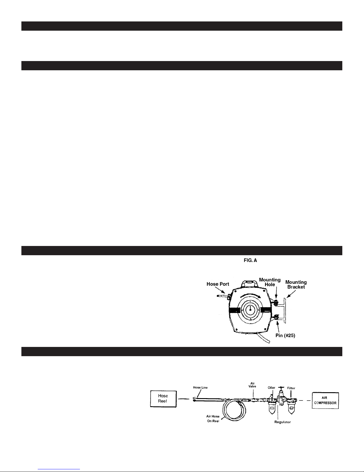
3. Mount the Hose Reel so that the Hose port is facing
up as shown in Figure 1.
4. Guide the Pins (#25) into the holes on the Mounting
Bracket (#11) until they snap into place. To remove the
Hose Reel, gently lift up on the Hose Reel to separate
it from the Mounting Bracket (#11) and pull it away from
the bracket.
1. You will need to prepare an air connector (not included)
to connect to the air inlet on the Supply Hose (#22) of
the Hose Reel. First, Wrap the air connector (not included)
with pipe thread seal tape before connecting to a
3/8 in. I.D. Air Source Hose (not included). Connect the
Air Source Hose to the Hose Reel.
2. Follow the same instructions for preparing the end of the
tool hose (#19)
Note: If you are not using an automatic oiler system,
before operation, add a few drops of Pnuematic Tool Oil
to the airline connection. Add a few drops more after each
WARNING: When using tools basic safety precautions should always be followed to reduce the risk of personal injury and damage to equipment.
OPERATION
UNPACKING & INSTALLATION
For best service you should incorporate an oiler, regulator,
and inline filter as shown in the diagram below.
SAFETY, WARNINGS & PERCAUTIONS
Maximum Working Pressure ....................................................300 PSI
Burst Pressure..........................................................................900 PSI
Air Outlet ............................................................3/8 in. - 18 Male NPT
Air Inlet ...............................................................3/8 in. - 18 Male NPT
Hose Dimensions ........................................................... 50 ft. x 3/8 in.
Inlet Hose ........................................................................ 36 in. Length

hour of continual use.
3. Do not exceed the maximum working air pressure of 300 PSI.
4. Check the air connection for leaks.
Operating the Hose Reel.
1. Slowly pull out the Hose (#19). You will hear a clicking noise after each revolution of the drum.
2. To latch or lock the hose in place, pull it out at least 2 clicks, and then allow it to retract to the previous click.
3. To unlatch or unlock the hose, slowly pull the hose until the clicking noise stops completely, then allow it to slowly and completely retract into the Hose Real.
Never allow the hose to retract quickly and without restraining the recoil speed.
Never let go of the end of the hose when it is rewinding.
Note: Before attempting to change the hose or swivel assembly, disconnect the air supply and release spring tension. Failure to do so may result in injury from a tightly
wound spring.
Note: Always wear ANSI approved safety goggles during maintenance.
Releasing Spring Tension
1. Make sure the Hose (#19) is pre-wound onto the reel and disconnect the Hose (#19).
2. Remove screws from the Locking Plate (#24)
3. Remove the screws from the Tension Plate (#3). When unscrewing the last screw,
hold the Tension Plate (#3) in place with one hand.
4. Hold your hands over both plates and allow both of the plates to spin in hand,
2-3 turns, to release the tension. See FIGURE 2.
Re-Tensioning The Spring
See FIGURES 2 & 3
1. Fully retract the hose.
2. Turn the Tension Plate (#3) in the rewind direction of the hose 2 to 3 revolutions and
hold it in place. Do not exceed 3 revolutions or you may permanently damage the spring.
Note: The arrow on the Tension Plate (#3) in place, replace the screws.
3. While holding the Tension Plate (#3) in place, replace the screws.
4. Align the Locking Plate (#24) onto the assembly using the Swivel (#16) as a guide. Replace the screws.
Note: The side plates are connected with brass and nylon shafts. Do not attempt to turn one side without
the other side turning simultaneously, or you will break the shaft.
Hose Replacement
See FIGURES 2, 3 & 4.
1. Pull the hose out to the final latched position.
2. Remove the four Screws (#2) on the Locking Plate (#24) and remove the plate.
3. Remove the four Screws (#5) securing the Mounting Bracket (#11).
4. Remove the four main Case Screws (#1) and lift off the Case Cover (#21)
Warning! Do not attempt to remove the reel from the case at this time as it is under
spring tension and may spring loose causing damage to the unit and personal injury.
Note: You will need a new Hose Clamp (#18B) to complete this operation.
5. Using the proper cutting tool (not included), cut the Hose Clamp (#18B) off of the
Swivel (#16). Be careful not to cut into the sleeve of the Swivel (#16).
6. Remove the hose from the Swivel (#16). If it is difficult to get off, slit the end of the
hose, but be careful not to cut into the sleeve of the Swivel (#16).
7. Pull off the old hose and remove the Ball Stop.
8. Insert the end of the new hose through the hole in the flange in the reel.
9. Heat the end of the new hose in hot water to soften it. Then, lubricate the end with
either vegetable oil or dish soap.
10. Slide the new Hose Clamp (#18B) onto the hose and push the end of the hose
onto the Swivel (#16). Then, slide the Hose Clamp (#18B) onto the hose and
Swivel (#16).
11. Neatly and evenly, wind the hose onto the reel.
12. Pull the hose end through the Hose Port of the case and attach the Ball Stop.
13. Release the spring tension by pulling the hose past the latched position.
If Additional tension is required, wrap the loose hose around the reel.
14. Replace the case, cover, and screws.
Replacing the Hub/Spring/Reel Assembly (#12)
See FIGURES 3 & 5
1. Release the tension spring following the instruction on page 5
2. Remove the Screws (#2) on the Locking Plate (#24) and remove it.
3. Remove Screws (#1) on the rear of the Case Cover (#21)
MAINTENANCE
OPERATION CONTINUED
PLEASE READ THE FOLLOWING CAREFULLY
THE MANUFACTURER AND / OR DISTRIBUTOR HAS PROVIDED THE PARTS DIAGRAM IN THIS MANUAL AS A REFERENCE TOOL ONLY. NEITHER THE
MANUFACTURER NOR DISTRIBUTOR MAKES ANY REPRENSENTATION OR WARRANTY OF ANY KIND TO THE BUYER THAT HE OR SHE IS QUALIFIED TO MAKE
ANY REPAIRS TO THE PRODUCT OR THAT HE OR SHE IS QUALIFIED TO REPLACE ANY PARTS OF THE PRODUCT. IN FACT, THE MANUFACTURER AND / OR
DISTRIBUTOR EXPRESSLY STATES THAT ALL REPAIRS AND PARTS REPLACEMENT SHOULD BE UNDERTAKEN BY CERTIFIED AND LICENSED TECHNICIANS AND
NOT BY THE BUYER. THE BUYER ASSUMES ALL RISK AND LIABILITY ARISING OUT OF HIS OR HER REPAIRS TO THE ORIGINAL PRODUCT OR REPLACEMENT
PARTS THEER TO, OR ARISING OUT OF HIS OR HER INSTALLATION OF REPLACEMENT PARTS THERE TO.

ASSEMBLY DRAWING
Part No. Description Qty
1 Screw 8
2 Screw 8
3 Tension Plate/Mode Switch 1
4 Case Cover 1
5 Screw 9
6 Outer Ring 1
7 Center Shaft 1
8 Spring 1
9 Latch 1
10 Nylon Nuts 2
11 Mounting Bracket 1
12 Hub/Spring Reel Assembly 1
Part No. Description Qty
14 Circlips 2
15 Brass Shaft 1
16 Swivel 1
17 Bent Pin 1
18B Hose Clamp 1
19 Hose 1
21 Case Cover 1
22 Supply Hose 1
24 Locking Plate 1
25 Pin 1
26 Spring 1
32 Handle 1
LIMITED WARRANTY
PERFORMANCE TOOL extends only the following warranties, and only to original retail purchasers. These warranties give specific legal rights. Except where prohibited by local law, the law of the State of Washington
governs all warranties and all exclusions and limitations of warranties and remedies. There may be other rights which vary from state to state.
PERFORMANCE TOOL warrants the product to be free from defects in materials and workmanship under normal use and service. A defective product may be returned for a free replacement within 90 days from the
date of purchase, provided that product is returned to place of purchase immediately after discovery of defect. After 90 days and up to 1 year from date of purchase, PERFORMANCE TOOL will replace at no charge
any parts which our examination shall disclose to be defective and under warranty. These warranties shall be valid only when a sales receipt showing the date of purchase accompanies the defective product or defec-
tive part(s) being returned. For part(s) after 90 days, please remit your request, postage prepaid to: PERFORMANCE TOOL, P.O. Box 24086 Seattle, WA 98124
These warranties exclude blades, bits, punches, dies, bulbs, fuses, and other consumables which must be replaced under normal use and service. These warranties shall not apply to any product or part which is used
for a purpose for which it is not designed, or which has been repaired or altered in any way so as to affect adversely its performance or reliability, nor shall these warranties apply to any product or part which has been
subject to misuse, neglect, accident or wear and tear incident to normal use and service.
PERFORMANCE TOOL does not authorize any other person to make any warranty or to assume any liability in connection with its products.
Except for warranties of title and the limited express warranties set forth above, PERFORMANCE TOOL makes no express or implied warranties of any kind with respect to its products. In particular, PERFORMANCE
TOOL makes no implied warranty of merchantability and no implied warranty of fitness for any particular purpose, except that for goods purchased primarily for personal, family or household use and not for commer-
cial or business use, PERFORMANCE TOOL makes an implied warranty of merchantability (and, if otherwise applicable, an implied warranty of fitness for a particular purpose), but only for the particular qualities or
characteristics, and for the duration, expressly warranted above. The laws on limitation of implied warranties may differ from state to state, so the above limitations may not apply in all cases.
PERFORMANCE TOOL shall not be liable for consequential, incidental or special damages resulting from or in any manner related to any product, or to the design, use, or any inability to use the product. The sole and
exclusive remedy for a defective product or part shall be the repair, or replacement thereof as provided above. The laws on limitation of remedies or on consequential, incidental or special damages may vary from state
to state, so the above limitations may not apply in all cases.
Copyright © 2014 PERFORMANCE TOOL – All rights reserved
Table of contents
Other PT Tools manuals
Popular Tools manuals by other brands

Würth
Würth DSA 8-S Translation of the original operating instructions

Crown
Crown CT18114 Original instructions

Alvin
Alvin PXB21 Operation and maintenance instruction

Polar Fire
Polar Fire B33Z08 Assembly instructions & parts diagrams

BikeMaster
BikeMaster 152148 user manual

BGS technic
BGS technic BGS 1924 instructions