TREND DJ300 User manual

DJ300
DOVETAIL JIG

DJ300
ITEMS ENCLOSED & DESCRIPTION OF PARTS
1 x 1/2” (12.7mm) Dovetail template
4 x Template bracket screws
countersunk socket head
1 x Hex key - 1/8” (3.2mm) A/F
2 x Template bracket complete with
integral nuts
No.1 Edge guides
For 1/2” (12.7mm) lapped dovetail
template
No.2 Edge guides
For 1/2” (12.7mm) rebated dovetail &
comb jointing template
2 x Template spring pin stops
2 x Edge guide pan head screws
2 x Edge guide screw washer
1 x Template guide bush 15.7mm
diameter
2 x Countersunk machine screw M5
x 10mm for guide bush
1 x Spanner 7/16” (11.1mm) A/F for
adjusting template lock nut
1 x Manual
1 x Guarantee Card
-2-
GUARANTEE
1 x Jig body
1 x Front clamping bar
(short) with abrasive
strip
1 x Top clamping bar (long)
with abrasive strip
4 x Nylon spacer
4 x Clamp knob female
4 x Clamp bar set bolt
UNC1/4” - 20 x 13/4
(long)
6 x Set bolt half nut
UNC1/4” - 20
2 x Template set bolt
UNC1/4” - 20 x 11/2
(short)
4 x Spring
2 x Template lock nut
UNC1/4” - 20
2 x Knurled brass thumb
screw
1 x Dovetail cutter
12.7mm dia x 104°
4 x Self tapping screw
No.10 x 1/2”

DJ300
SAFETY PRECAUTIONS
■Always switch off the power and unplug the
router when changing cutters or when making
adjustments.
■Always wear protective goggles when routing.
■Wear sound protective ear muffs when routing
for long periods of time.
■Always wear a dust mask or respirator. Use
dust extraction equipment whenever possible.
■Do not wear loose clothing. Make sure baggy
sleeves are rolled up and ties are removed.
■Always remove spanners and hex keys from
the workpiece before switching router on.
■Keep hands well clear of the router cutter
when routing.
■Avoid accidental starting of the router. Make
sure the power switch is in the ‘Off’ position
before plugging in and connecting to the
electrical supply.
■Never leave the router unattended when
running. Always wait until the router comes to
a complete stop before making any
adjustments.
■Do not switch the router on with the cutter
touching the workpiece.
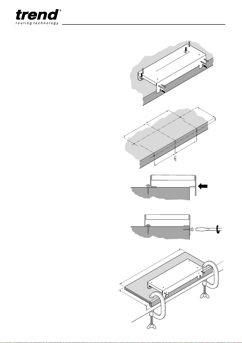
■Mount the Dovetail Jig securely to a work
bench or to a workboard fitted to a suitable
surface.
■Periodically check all nuts and bolts to make
sure they are tight and secure.
■Use dust extraction equipment.
Cutter Care
■Do not drop cutters or knock them against
hard objects.
■Cutters should be kept clean. Resin build-up
should be removed at regular intervals with
Resin Cleaner®. The use of a dry lubricant
will act as a preventative such as Trendicote®
PTFE spray.
■Cutter shanks should be inserted into the
collet at least 3/4of shank length to prevent
distortion. A distorted collet should be
discarded, as it can cause vibration and
damage the shank.
■Do not overtighten collet as this will score the
shank and create a weakness.
■It is also advisable to periodically check the
router collet nut for wear.
Useful Advice
■Judge your feed rate by the sound of the
motor. In time, the operator will acquire a
‘feel’ for the router and a feed speed relative
to the work will come naturally. Too slow a
feed will result in burning.
■Apply the normal precautions as with any
electric power tool.
■The main cause of routing machine failure is
the inclination for operators to overload them.
The motto is ‘Keep the revs up’. The drop in
revolutions should not exceed, if possible,
more than 20% of full running speed.
■The motor of a router is susceptible to the
accumulation of sawdust and wood chips and
should be blown out, or ‘vacuumed’,
frequently to prevent interference with normal
motor ventilation.
■Refer to the Instruction Manual supplied with
your router for full details of it’s features and
safety information.
■The use of a fine height adjuster is highly
recommended (if available for your router) for
accurately adjusting the height of the cutter
when dovetailing.
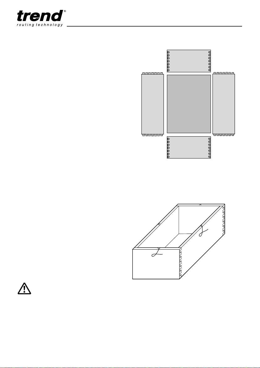
■Trial cuts should be made on waste material
before starting any project.
-3-

DJ300
1. Clamp knob female
2. Nylon spacer
3. Clamping bar - short
4. Clamping bar - long
5. Spring
6. Template spring pin stop
7. 1/2” (12.7mm) dovetail template
8. Template bracket screws
9. Template bracket
10. Dovetail edge guide
11. Edge guide pan head screws
ASSEMBLY
Using the drawing below as a guide to assemble
the jig.
12. Edge guide washer
13. Clamp bar set bolt UNC1/4” - 20 x 13/4” (long)
14. Knurled brass thumb screw
15. Edge guide fastening slot
16. Jig body
17. Lock nut UNC1/4” - 20
18. Embossed slot for bar set bolt (front slots
hidden from view on diagram above)
19. Template set bolt UNC1/4” - 20 x 11/2” (short)
20. Half nut UNC1/4”- 20
21. Embossed slot for template set bolt
-4-
4
16
18
13
20
19
18
20
351421 18 1715 2 1
10
12
11
1
2
5
8
7
9
6
13
19
20
13
18
21
20
13

DJ300
Assembly Instructions
■To fit the four clamp bar set bolts (13), firstly
insert the half nut (20) into the embossed
slot(18) in the jig body (16). For the clamp
bar set bolts the two back top embossed
holes and the two front inner embossed slots
are used. Assembling one assembly at a time
fit the clamp bar set bolt (13) into the half nut
(20) from inside the jig body (16). Tighten
using the spanner enclosed. Repeat for the
remaining three bolt assemblies.
■To fit the two template set bolts (19), firstly
insert the half nut (20) into the two outer front
embossed slots (21) in the jig body (16).
Screw the template set bolt (19) into the half
nut (20) from inside the jig body (16). Tighten
using the spanner enclosed. Repeat for the
other bolt assembly.
■Fit the edge guides marked 1L (left-hand) &
1R (right-hand) to the dovetail body (16),
securing them with the edge guide washer
(12) and pan head screws (11) through the
fastening slots (15) and into the tapped holes
in the top of the body of the jig.
■Screw the lock-nut (17) onto each of the
template bolts (19) on the front of the dovetail
body, followed by the knurled brass thumb
screw (14), keeping the knurled side to the
front. Adjust the lock-nuts so that they are
both 8mm from the jig body using the spanner
provided.
-5-
■To install the clamping bars, identify front
clamping bar - short (3) and top clamping bar
- long (4).
■Fit spring (5) onto the clamp bar set bolt (13)
and the fit clamp bar (3) or (4) on the set bolt
(13). Fit the nylon spacer (2) onto the set bolt
(13). (When using material, with a thickness
greater than 23mm, the nylon spacer must be
removed).
■Thread the female clamp knob (1) onto the
set bolt (13). Fit both front and top clamp
bars in the same way.
■Using a hammer, gently tap the two template
spring pin stops (19) into the holes in the
edge of the template (7). (This procedure is
also required for the 1/4” (6.35mm) template
accessory ref. DJ300/01).
■Attach the aluminium template (7) to the
template brackets (9) with the four socket
head countersunk screws (8).
■Slide the template by engaging the slots of
the template brackets (9) over the bolt (13).
Lightly tighten the knurled brass thumb
screws (14).
The jig will need to be mounted onto the
workbench or false work surface as shown on
page 8.
16
18 or 21
2020
13 or 19
IMPORTANT!
Periodically check tightness of
all nuts and bolts.

DJ300
Standard 1/2” (12.7mm)
Template
The DJ 300 Dovetail Jig is supplied with a
standard 1/2” (12.7mm) dovetail template
and will produce lapped dovetail and
lapped rebated dovetail joints. The
15.7mm template guide bush and the
12.7mm (1/2”) diameter x 104° Dovetail
router cutter should be used and are
supplied with the jig.
Specification
Min material thickness is 12mm.
Max material recommended is 20mm.
Pitch width is 25.4mm.
Specification
Min material thickness is 8mm.
(A 6mm plywood or MDF packing piece behind
front bar is required.)
Max material recommended is 12mm.
Pitch width is 11.3mm.
Specification
Min material thickness is 11mm.
Max material thickness is 25mm.
Pitch width is 21.5mm.
Optional 1/2” (12.7mm) Comb
Joint Template Ref. DJ300/02
The comb joint is ideal for strong corner
joints for boxes. The finger size are 1/2”
(12.7mm) in diameter. The template uses
the 15.7mm guide bush (ref. GB157) as
supplied with the standard dovetail jig.
The cutter is not supplied as standard.
The principle for setting-up and routing
the comb is different to that for the
dovetail, each piece is routed separately
under the front clamp bar.
Also included with the optional 1/2”
(12.7mm) comb are edge guides No. 3.
Optional 1/4” (6.35mm) Lapped
Dovetail Template Ref. DJ300/01
The size of dovetail is 1/4” (6.35mm) and
is ideal for small boxes and small drawers.
The template includes a 7.74mm guide
bush (ref. GB774).
The cutter is not supplied as standard.
The principle for setting-up and routing
the dovetail is the same as for the
standard 1/2” (12.7mm) dovetail template.
The edge guides No. 3 and No. 4 are
supplied with the optional 1/4” template
(6.35mm).
-6-
Template Specification
12.7mm (1/2”) dovetail
cutter ref. L120 (UK &
Eire), C041 (Europe)
6.0mm dovetail cutter
ref. S31/11 (UK &
Eire), C154 (Europe)
Comb Joint
1/4” (6.35mm)
Lapped Dovetail 1/4” (6.35mm) Lapped
rebated dovetail
1/2” (12.7mm)
Lapped Dovetail 1/2” (12.7mm) Lapped
rebated dovetail
12.55mm x 25mm
straight cutter ref.
3/76 (UK & Eire)
C021A (Europe)
Pin Pin Depth
9.5mm (
3
/
8
”)
Pin With
12.7mm (
1
/
2
”)
Pin Width
6.3mm (
1
/
4
”)
Pin Depth
20mm Max
Pin Width
12.7mm (
1
/
2
”)
Pin Depth
4.8mm (
3
/
16
”)

Included with Dovetail Jig
DJ300
DJ300/01
1/4” (6.35mm) Dovetail
Template
DJ300/02
1/2” (12.7mm) Comb
Template
No. 1
Edge Guides for 1/2”
(12.7mm) Lapped Dovetails
No. 2
Edge Guides for 1/2”
(12.7mm) Rebated Dovetails
Supplied with 15.7mm
diameter bush (ref. GB157)
No. 3
Edge Guides for 1/4”
(6.35mm) Lapped Dovetail
No. 4
Edge Guides for 1/4”
(6.35mm) Rebated Dovetail
Supplied with 7.74mm
diameter bush (ref. GB774)
and Hex key 1/8” (3.2mm) A/F
-7-
Supplied with Hex
key 1/8” (3.2mm) A/F
Standard 1/2” (12.7mm) Dovetail
Template
Included with 1/4” (6.35mm)
Dovetail Template
Included with Dovetail Jig
Included with 1/2” (12.7mm)
Comb Template
No. 2
Edge guides as used for
rebated 1/2” (12.7mm)
dovetails.
Uses standard guide bush
(ref. GB157)
No. 3
Edge guides for future use

DJ300
-8-
Mounting Instructions
Attaching Jig to Workbench
The jig should be secured to a workbench or
false work surface with the four screws supplied.
A false surface will protect the workbench and
can be quickly clamped with quick release
clamps.
Two screw locations are provided at the rear of
the jig and two on the lip at the front.
■Mark the positions of the pilot holes for the
screws as shown.
■Drill 1/8” (3.2mm) pilot holes at these
locations.
■Screw two of the No. 10 x 1/2” self tapping
screws in the work top and leave the screw
heads 2mm proud of the surface.
■Slide the jig over the two screw heads until
they locate.
■Use the two remaining self tapping screws to
secure the lip of the jig to the workbench or
false work surface. The jig is now secure and
ready to use.
Making a False Work Surface
■This can be constructed from 12mm to 18mm
MDF or similar material with a lip on the front
which will hook over the front of the
workbench. Suitable quick action clamps or
similar can then be used.
138mm
190mm
175mm
10mm
190mm
175mm
620mm
250mm
40mm

DJ300
-9-
■Fit the 1/2” (12.7mm) dovetail cutter keeping
3/4of the shank length in the collet.
Adjust the height of the cutter so that it
protrudes approximately 17mm from the base
of the router for 1/2” (12.7mm) dovetails and
11mm for 1/4” (6.35mm) dovetails. After a trial
joint, slight adjustment may be required to
ensure a well fitting joint. As the guide bush
is recessed into the base of the router, these
measurements should be taken from the
router base not from the guide bush.
Making a Router Stand Block
■As the cutter for dovetailing should not be
retracted into the router, a useful aid is a
Router Stand Block. This is simply a piece of
scrap timber with a hole large enough to take
the protruding guide bush and dovetail cutter.
This will allow the router to stand up safely
between operations.
Setting-up the Router
■Fit the guide bush to the base of the router.
■Fit a fine height adjuster if available, as this
will make it easier to adjust the height
accurately. The fine height adjuster is not
required for comb jointing.
■Lower and lock the router carriage so that the
collet is close to the guide bush, but not
touching it.

DJ300
TIMBER PREPARATION
It is important to plan your work before starting
to save set-up time and avoid costly mistakes.
Both sides of the jig can be used to make the
dovetail joints. However, only clamp one pair
into the jig at any one time to ensure it is
clamped securely.
When joining multiple pieces for a drawer or
series of drawers, label the pieces as front, back,
sides and which face will be inside or outside.
Label the pieces so it is clear which end mates
with each other (see diagram).
The ‘A’ parts will be clamped under the front
clamping bar and the ‘B’ under the top clamping
bar. Even numbers will be placed against the
left-hand edge guide and the odd numbers
against the right-hand edge guide.
A typical 1/2” (12.7mm) dovetail drawer has a 3/4”
(19mm ) thick front with sides made of 1/2”
material. The dovetail jig’s design requires that
you use the same stock thickness for the back
as you do for the front, if you are cutting joints
simultaneously. Your drawer fronts and backs
must be at least 5/8” (16mm) thick to fully
accommodate the length of the dovetails without
compromising strength.
Before joining the actual timber components,
make a trial cut on scrap timber. This will
familiarise you with the jig and check all
dimensions used.
After all the pieces have been cut to size and
checked to ensure squareness, set them on a
bench in the order and they will be fitted
together. Lay each piece down so the inside
faces up and label each piece on the inside as
shown.
-10-
Inside
Front
Inside
Left
Side
A4 A3
A1 A2
B4 B3
B1 B2
Drawer
Bottom
Inside
Back
Inside
Right
Side
A4 A3
A1 A2
B4
B3
B1 B2
IMPORTANT!
The dimensions shown in these
instructions are subject to
acceptable tolerances in the
manufacture of the guide bush,
template and cutter. Therefore
use the setting dimensions as
guidance only and make a trial
cut in scrap timber before
starting every project.

7.5mm
2mm
15mm
3mm
DJ300
-11-
1
/
2
” (12.7mm) Dovetail Template
(21.5 mm pitch with 3mm offset line)
No. of whole tails
123456789...
21.5 43 64.5 86 107.5 129 150.5 172 193.5
Optimum width of timber in mm
ie Pitch x No. of tails = Width (when 3mm offset line used).
1
/
4
” (6.35mm) Dovetail Template
(11.3 mm pitch with 2mm offset line)
No. of whole tails
123456789
11.3 22.6 33.9 45.2 56.5 67.8 79.1 90.4 101.7
Optimum width of timber in mm
ie Pitch x No. of tails = Width (when 2mm offset line used).
Timber Widths
■Any width of timber up to 300mm wide can be
dovetail jointed. To obtain a symmetrical joint
with full tails and pins at each end, see the
chart on the right for the recommended widths
of timber.
■The edge guides have a built in offset to
produce exact fitting dovetail joints. Their
position is adjustable to enable a symmetrical
joint to be obtained with timber widths that are
not ideal. Their position can be simply be
judged by eye.
Making a Setting Block
To eliminate unnecessary measurements being
made should you change the settings of the jig
(e.g. when using other templates or adjusting the
jig for awkward widths of timber). One should
make a setting block which should be kept safe
and used to set up the jig to create a standard
1/2” (12.7mm) dovetail joint or optional 1/4”
(6.35mm) dovetail joint.
Make the setting block as follows:
■Use timber that is uniform in thickness and
has a square end.
■Draw a line 3mm from the left and right edge.
(2mm for 1/4” (6.35mm) dovetail template).
This will be used to set the left and right edge
guides.
■Draw a line 15mm from the front edge.
(7.5mm for 1/4” (6.35mm) dovetail template).
This offset will be used to set the template
position.
Setting-up the jig with this block is shown
overleaf.
1/2” (12.7mm) Dovetail
1/4” (6.35mm) Dovetail

OPERATION
Setting-up for Dovetailing
With the standard 1/2” (12.7mm)
Dovetail Template or the optional 1/4”
(6.35mm) Dovetail template.
Setting the Jig using the Setting-up
Block
■Fit the Edge Guides and leave the screw
slightly loose (1).
■Position a scrap piece of timber (2) under the
front clamp, slightly proud of jig surface and
well away from the edge guide and clamp it in
this position (3).
■Place the setting block under the top clamp
and butt it up to the scrap piece (1). Fit the
template onto the jig and lay it on top of the
timber (2). Tighten the knurled brass thumb
screw (3). Slide the setting block until the
offset line is aligned with the left hand edge of
the first slot (4). See drawings below.
Tighten the top clamps making sure the
setting block does not move (5).
DJ300
-12-
Fit No. 1 for 1/2”
(12.7mm) lapped dovetail Fit No. 3 for 1/4”
(6.35mm) lapped dovetail
For 1/2” (12.7mm)
lapped dovetail For 1/4” (6.35mm)
lapped dovetail
1
4
5
3
2
2mm offset line3mm offset line
2
3
1
IMPORTANT!
When using 1/4” (6.35mm)
dovetail template the minimum
material thickness is 8mm. A
6mm packing piece (plywood
or MDF) behind the front bar
will be required to ensure the
clamp tightens properly.

■Slacken the brass thumb screw (1). Using the
spanner supplied (2), adjust the position of
the lock-nuts until the back of the template
slots align with the Template Setting Line (3).
■Remove the template (1). Slide the edge
guide up to the edge of the setting block (2).
After ensuring it is square, tighten the edge
guide securely (3).
Repeat the setting procedure for the right-
hand edge guide.
■Remove the setting up block and the scrap
timber and keep it safe. The jig is now ready
to use.
■For each joint, clamp the two pieces of timber
under the clamps making sure both are flush
with each other and touching the edge guide.
Place even numbers against the left-hand
edge guide and the odd numbers against the
right-hand edge guide.
7.5mm
template
setting
line
DJ300
1/2” (12.7mm) Dovetail Template Optional 1/4” (6.35mm) Template
-13-
2
1
3
A2
B2
or A4 and B4
A1
B1
or A3 and B3
15mm
template
setting
line
3
21
IMPORTANT!
Only clamp and rout one set at one time
to ensure maximum clamping action of
the clamp bars.
Tighten up top and side clamps evenly
and tighten the template securely.
DO NOT OVERTIGHTEN.

DJ300
Routing the Joint
■Start up the router and make one very light
cut from right to left, machining only the front
edge. This will prevent chipping out at the
next stage.
■Now carefully rout from left to right following
the guide bush in each of the slots.
Examine each of the slots to ensure all the
material have been cleanly routed. If you
discover that there are parts of the joint that
have not been cleanly routed, without
adjusting the jig, rout the joint a second time.
■Remove material and try the joint.
Follow the table below if the joint is not as
expected.
Dovetail joint Increase depth
too loose adjustment of cutter.
Dovetail joint Decrease depth
too tight adjustment of cutter.
Dovetail joint Move template comb
too shallow towards the jig body.
Dovetail joint Move template comb
too deep away from jig body.
Adjust the jig accordingly and re-align the two
pieces carefully in the jig and rout them again.
-14-
IMPORTANT!
Do not lift the router from the
template with the guide bush
engaged in the slots as damage
to the template will occur.

DJ300
Rebated Dovetails
The technique for setting and routing rebated
dovetails are similar to flush lapped dovetails
except, the drawer front and side are routed
separately and the drawer front must overhang
the jig when routing to allow for the rebate.
Drawer Front Preparation
■Prepare the drawer front with a 3/4” (19mm)
longer and 3/4”(19mm) wider dimension than
the drawer size required.
Rout a 3/8” (9.5mm) wide by 7/16” (11.1mm)
deep rebate around the inside of the drawer
front, using the rebate cutter ref. 46/39 or
C040 fitted with ball bearing ref. B16A.
■Fit the appropriate edge guides and leave
slightly loose. See below:
■Fit the template to the jig (1) & tighten brass
thumb screw (2).
To ensure an overhang of 3/8” (9.5mm) of the
drawer front, slide a piece of scrap timber 3/8”
(9.5mm) thick under the front clamp (3),
ensuring it is well away from the edge guide.
See (A).
Alternatively use a scrap piece of timber with
a 3/8” (9.5mm) deep rebate. See (B).
Clamp it in position (4).
-15-
Fit No.4 Edge Guide
for the 1/4” (6.35mm) Rebated Dovetail Template
Fit No.2 Edge Guide
for the 1/2” (12.7mm) Rebated Dovetail Template
1
2
3
4
9.5mm
(3/8")
11.1mm
(7/16")
INSIDE
AB
3/8"
B16A

2
3
1
DJ300
■Place the drawer front under the top clamp (1)
and make sure it is flush with the 3/8” (9.5mm)
timber.
Slide the drawer front until the offset line
aligns with the left edge of the first slot (2).
Clamp the timber securely (3).
■Slacken the brass thumb screw (1). Using the
spanner supplied (2), adjust the position of
the lock-nuts until the back of the template
slots align with the Template Setting Line (3).
■Remove the template (1).
Slide the edge guide up against the drawer
front (2).
Tighten the edge guide securing screw (3).
Replace the template.
Edge Guide Setting Line
for the 1/4” (6.35mm)
Dovetail Template
Edge Guide Setting Line
for the 1/2” (12.7mm)
Dovetail Template
1/2” (12.7mm) Dovetail Template
Optional 1/4” (6.35mm) Template
-16-
3
2
1
2mm offset line
3mm offset line
7.5mm
template
setting
line
15mm
template
setting
line
Using
3/8” (9.5mm)
scrap timber
Using
3/8” (9.5mm)
rebated scrap timber
3
21
IMPORTANT!
Timber must be moved over by
one finger on template in order
to locate edge guide.

DJ300
Routing the Drawer Front
■Fit the correct guide bush and cutter.
Rout from right to left following the guide bush
in each of the slots.
The drawer front is now finished.
For drawer fronts with a different size of
rebate, adjust dimensions accordingly.
Routing the Side
■This again is routed separately. Slide a scrap
piece of timber (1), the same thickness as the
side, under the top clamp. This is to prevent
tear-out.
Insert the side piece (2) under the front clamp
and align it with the scrap piece (1) and the
Try-square (3).
Clamp it in this position (4).
Rout as per normal lapped dovetail (see page
14 – Routing the Joint).
■Remove the side piece and check the joint.
Use the chart on page 14 for adjusting the fit
if necessary.
-17-
4
2
13
Setting the depth of cut in the future
To ease setting up of the cutter height in the
future, rout a joint using the setting-up block in
the same position as a drawer front. Then use
this to accurately set the depth of cut of the
cutter in the future.
IMPORTANT!
Referring to the marking out of
the timber on page 10 please
place even numbers against the
left-hand edge guide and the
odd numbers against the right-
hand edge guide when routing.

DJ300
Comb Jointing with the Optional Comb
Template
The comb template is secured to the jig in the
same manner as the dovetail templates.
The GB157 guide bush as supplied with the
standard jig should be used together with a
12.55mm dia. straight two flute cutter ref.
3/76 or C021A.
■Assemble the template to the template
brackets using the machine screws supplied.
■Fit the guide bush and cutter to the router.
■The comb joint is best routed in two or three
passes at increased depths. Therefore the 3
step turret stop fitted to most routers is ideal
for this purpose.
The technique for setting and routing comb joints
requires each piece to be clamped in the front
clamp and routed separately. A wider piece of
scrap is clamped under the top clamp to stop
tear-out and provide support for the router. The
scrap must be at least 1/4” (6.35mm) thicker to
ensure you do not rout into the body of jig.
When using timber over 16mm thick the nylon
spacers on the clamp knob will need to be
removed.
Timber Preparation
■Cut all four pieces for the box to the exact
dimensions of the final unit. Make sure that
all ends are perfectly square and exact
widths.
■Mark the centre line on both pieces of
material and mark a 1.6mm (1/16”) offset to
the left and to the right of the centre line.
■Label the piece as shown in the diagram.
-18-
1.6mm
offset
line
1.6mm
offset
line
Use No.2 Edge Guides
for the Comb Template
A4
A3
B1 B4
A1
A2
B2 B3
B4
B3
B1
B2
A4
A3
A1 A2

1
/
2
” (12.7mm) Comb Template
(25.4mm pitch with Symmetrical Sockets)
No. of Sockets
123456789...
38.1 63.5 88.9 114.3 139.7 165.1 190.5 215.9 241.3
Optimum width of timber in mm
ie (Pitch x No. of Sockets) + 12.7mm = Width.
DJ300
Setting up the Jig
■Fit the edge guides marked No. 2 and leave
slightly loose.
■Fit the comb template to the jig.
Slide a packing piece which is at least 1/4”
(6.35mm) thicker than the timber for the joint,
under the top clamp, flush with the front of the
jig and well away from the edge guide.
Clamp it in position.
■To set the left-hand edge guide, slide the first
box side (1) under the front clamp, keeping the
top edge flush underneath the template. Align
the left-hand offset line with the edge of a
finger (2).
Clamp the piece in this position (3).
-19-
1
2
3
1
1.6mm
offset
Timber Widths
■Any width of timber up to 300mm wide
can be comb jointed, however to
obtain an even looking symmetrical
comb joint where there is an extra
pin/socket, the timber must be
machined to a width shown in the
chart.
■For timber that is not machined to the
recommended width, either the end
pin/sockets will need to be narrow or
an un-symmetrical comb will have to
be machined.
Symmetrical
Extra pin/socket Symmetrical
Reduced End
pin/socket
Non-symmetrical
Even number
of pins/sockets

DJ300
■Remove the template (1), slide the edge
guide up against the box side (2) held
under the front clamp. Then tighten the
edge guide securing screw (3).
■Repeat the setting up operation for the
right-hand side edge guide using the right-
hand off-set line.
■Ensure the packing piece supports the
whole width of the box side, otherwise
breakout could occur when routing.
Routing the Joint
■Set the depth of cut as follows:
3 to 6mm - one pass
6 to 12mm - two passes
12 to 18mm - three passes
The full depth of cut should be the same as
the thickness of the box side. A slightly
deeper cut can be made if finishing is
desired. However be careful not to rout into
the body of the jig.
■To ensure a correctly fitting and a mirrored
joint is obtained, place the pieces marked
‘A’ against the left hand edge guide and
the ‘B’ piece against the right hand edge
guide.
■Rout from left to right following each finger.
■Repeat the above steps for each box side.
■If the ends of the box sides are not flush
then adjust the 1.6mm offset accordingly.
■Check the joints by assembling them dry.
Any extra length to the fingers can be
routed down and sanded off.
-20-
1
2
3
Table of contents
Other TREND Tools manuals

TREND
TREND MINIMACH User manual

TREND
TREND PH/JIG/M User manual

TREND
TREND PRO GRABIT 4pc User manual

TREND
TREND H/JIG/B User manual

TREND
TREND RS/JIG User manual

TREND
TREND HINGE/JIG User manual

TREND
TREND PH/JIG/BS User manual

TREND
TREND VJS/AG/36 User manual

TREND
TREND PRO POCKET HOLE JIG User manual

TREND
TREND ELLIPSEJ/A User manual