HITROL HT-100F Series User manual

HT-100F Series
HITROL CO., LTD. 1
HITROL CO., LTD.
HEAD OFFICE. FACTORY. R&D INSTITUTE
HITROL CO., LTD., 141, Palhakgol-gil, Jori-eup,
Paju-si, Gyeonggi-do, Korea
TEL.: (00)-82-31-950-9700
FAX: (00)-82-31-943-5600
www.hitrol.com
INSTRUCTION MANUAL
FLOAT-TYPE LEVEL TRANSMITTER
HT-100F(I) Series
Doc. No.: HT100F_IM_Eng_Rev.2
Date Issued: 2019.10
HT-100F Series
HITROL CO., LTD. 2
You should be careful where CAUTION is marked to carry
outthework.
You should be well-informed of the contents where
WARNING is marked before carrying out the work.
.
You should be aware of where NOTICE is marked to carry
outthework.
Table of Contents
Overview and Features · · · · · · · · · · · · · · · · · · · 3
Mechanism and Components · · · · · · · · · · · · · · · 3
Specifications · · · · · · · · · · · · · · · · · · · · · · · · · · 4
Specifications of the R/I Converter · · · · · · · · · · · · 4
Float Application Table· · · · · · · · · · · · · · · · · · · ··5
Components · · · · · · · · · · · · · · · · · · · · · · · ····5
Dimensions · · · · · · · · · · · · · · · · · · · · · · · · ····6
Wiring and Cautions · · · · · · · · · · · · · · · · · · · ··6
Zero/Span Adjustment · · · · · · · · · · · · · · · ······7
Maintenance · · · · · · · · · · · · · · · · · · · · · · ·····8
Attachment and Cautions· · · · · · · · · · · · · · · · ··· 9
Cautions for Removal · · · · · · · · · · · · · · · · ····10
Cautions for Installation · · · · · · · · · · · · · · ·· 10
Cautions for the Inserted External Wire · · · · · · 10
Safety and Environment · · · · · · · · · · · · · · · · 10
Marking · · · · · · · · · · · · · · · · · · · · · · · · · · 10
User Training· · · · · · · · · · · · · · · · · · · · · · · 11
Troubleshooting · · · · · · · · · · · · · · · · · · · · · 11
Output Signal of 4mA or Less · · · · · · · · · · · · · 11
Output Signal of 20mA or More · · · · · · · · · · · · 11
Holding of the Output Current · · · · · · · · · · · · · 11
Hunting of the Output · · · · · · · · · · · · · · · · · · 11
Warranty and Contact · · · · · · · · · · · · · · · · · 12
Warranty and Service · · · · · · · · · · · · · · · · · · · 12
Headquarters / Factory / Research Center · · · · · · 12

HT-100F Series
HITROL CO., LTD. 3
Overview and
and Features
Mechanism and
Components
■Wire type for easy installation
■Local indication (indicator)
■Easy maintenance
The HT-100F Series is a float-type level transmitter for continuously measuring
the liquid level in a container with buoyancy. It is mainly used to measure liquid for
purification, industrial water, sewage treatment plants, wastewater, and fuel tanks.
When the float, which is fabricated according to the specific gravity of the target to
be measured, moves up and down along the liquid surface with buoyancy, the wire
connected to the float is wound around the wire drum by the constant spring.
The rotation of the wire drum is transferred to the gear and, thus, triggers the
indicator pointer.
The magnet in the indicator pointer triggers the reed switch to change the resistance
value.
The changed resistance value is detected by the R/I converter in the housing and
corresponding current value (DC 4-20mA) is continuously output. The HT-100FI has
the local indicator pointer so that it can be checked on site.
<Front>
<Back>
HT-100F Series
HITROL CO., LTD. 4
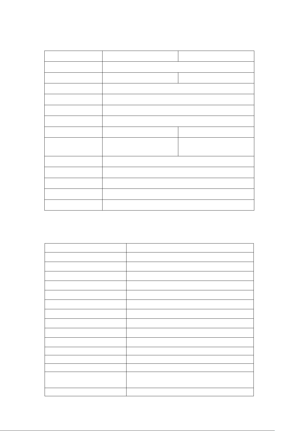
Specifications
Model
HT-100F
HT-100F(I)
Mounting
Top, Flange
Indicator
None
1-point dial
Ambient Temperature
−20°C ~ +60°C
Process Temperature
Max. 80°C
Process Pressure
ATM
Range (m)
Max. 7.5m
Power Source
DC 24V
None (Std.) / DC 24V (Opt.)
Output
DC 4~20mA (2-wire)
Display (Std.) /
DC 4~20mA (2-wire) (Opt.)
Enclosure
Weather-proof (IP54)
Wetted Parts Material
316L SS
Process Connection
100A JIS 10K FF (Std.)
Cable Entry
PF 1/2"(F)
Accuracy
±2% of F.S.
Specifications of the
R/I Converter
Item
Specification
Micom
16bit microprocessor
Supply Voltage
+17 ~ +40V at Typ. +24V
Operating Voltage
+3.3V
Current Consumption
2.5mA or less at sensor 1KΩ
Status Indicator
Bi-color LED (green/red/orange)
Zero/Span Set
Tact switch
Wire Connection
One-touch connector
Ambient Temperature
−20°C ~ +60°C
Dimension
80mm ×65mm ×20mm
Weight
54g
Current Loop Interface
2-wire loop current
Output Current Range (Accuracy)
4~20mA within ±0.2%
Output Current Offset
±0.2mA at 0.01mA / 20 steps
Measurement Sensor Range
30KΩ(15M) at sensor 10Ω
Min.: 200Ω(100mm) / Max.: 50KΩ(25M) at sensor 20Ω
Output Current Definite
TP

HT-100F Series
HITROL CO., LTD. 5
Float Application Table
Float Size
Spring Length
MEAS. Range
S.G
Range
Outer
Diameter
Length
Min
89.1
200
5 m / ~3.5 m
0.7
7.5 m / ~6 m
0.7
10 m / ~7.5 m
0.8
76.3
250
5 m / ~3.5 m
0.7
7.5 m / ~6 m
0.7
10 m / ~7.5 m
0.8
Components
Aluminum Housing
Aluminum Housing
(Indicator Type)
Flange
CS, 304, 316L
Float
304, 316L
Protection Tube
304, 316L
Flange
CS, 304, 316L
Outside
Wetted Parts
Material
Float
304, 316L
<Wire Type>
<Protection Tube Type>
Vent Hole

HT-100F Series
HITROL CO., LTD. 6
Dimensions
<HT-100F>
<HT-100FI>
<HT-100FI Guide Type>
Wiring and
Cautions
R/I Converter
■+ −: DC 24V (DC 4~20mA Loop)
■T: Output Test Point
■H.C.L: Wire to Connect the Sensor and R/I converter
* Cable color: H –Red, C –White, L –Black
■Make sure to connect the power with correct polarity (+, −).
■The power supply must be between +17 and +40V.
■Do not connect the wire with the power connected.

HT-100F Series
HITROL CO., LTD. 7
Zero/Span
Adjustment
Green LED is turned on
when the power is connected
and wiring properly.
S
Step 1
Step 2
Step 4
Step 3
Press and hold the button for 3s
to finish zero/span setting with
the green LED on and then off.
▷Steps 2 and 3 can be interchanged.
▷For the zero (0%) setting, proceed with Step 1 Step 2 Step 4.
▷For the span (100%) setting, proceed with Step 1 Step 3 Step 4.
Caution: Incorrect setting may lead to an incorrect range setting with the orange LED
on and then off.
■Offset
Adjust the error of measuring device or fine tuning of level.
S
M
S
M
S
M
Step 1
Step 2
Step 3
Press the + buttons for 3s
to turn on the red LED.
With the button pressed, press the
/ button for fine tuning.
to adjust it.
or
or
Press the +buttons for 3s
to finish the offset with
the green LED on and then off.
▷Span◁
▷Zero◁
▷Offset adjustment is available regardless of float position.
Press the button
with the float at
0% position.
Press the button
with the float at
100% position.
With the button pressed, press the
/ button for fine tuning.
to adjust it.
HT-100F Series
HITROL CO., LTD. 8
Maintenance
The HT-100F Series level transmitter requires inspection for the sensor, drive, and transmission
sections. The sensor section has REED S/W; the drive section has the wire drum, spring drum,
and spur gear; and the transmission section has the R/I converter.
The service life of parts depends on the operation conditions, and regular inspection is
required to keep the optimum operation conditions. Thus, users are advised to conduct regular
inspection and maintenance at least every year. Exterior damages will be visually checked. The
R/I converter can be checked using a digital multimeter.
<Checking of the Sensor>
Disconnect the sensor wire from the H, C, and L terminals of the R/I converter, and
measure the resistance value of the sensor.
Low and Com
Resistance value of the current level
High and Com
Resistance value of the full level –Resistance value of the current level
High and Low
Resistance value of the full level
<Checking of the Drive>
1. Remove the front cover to see the gear operation.
2. Remove the rear cover to check the wire and measuring tape for any damage.
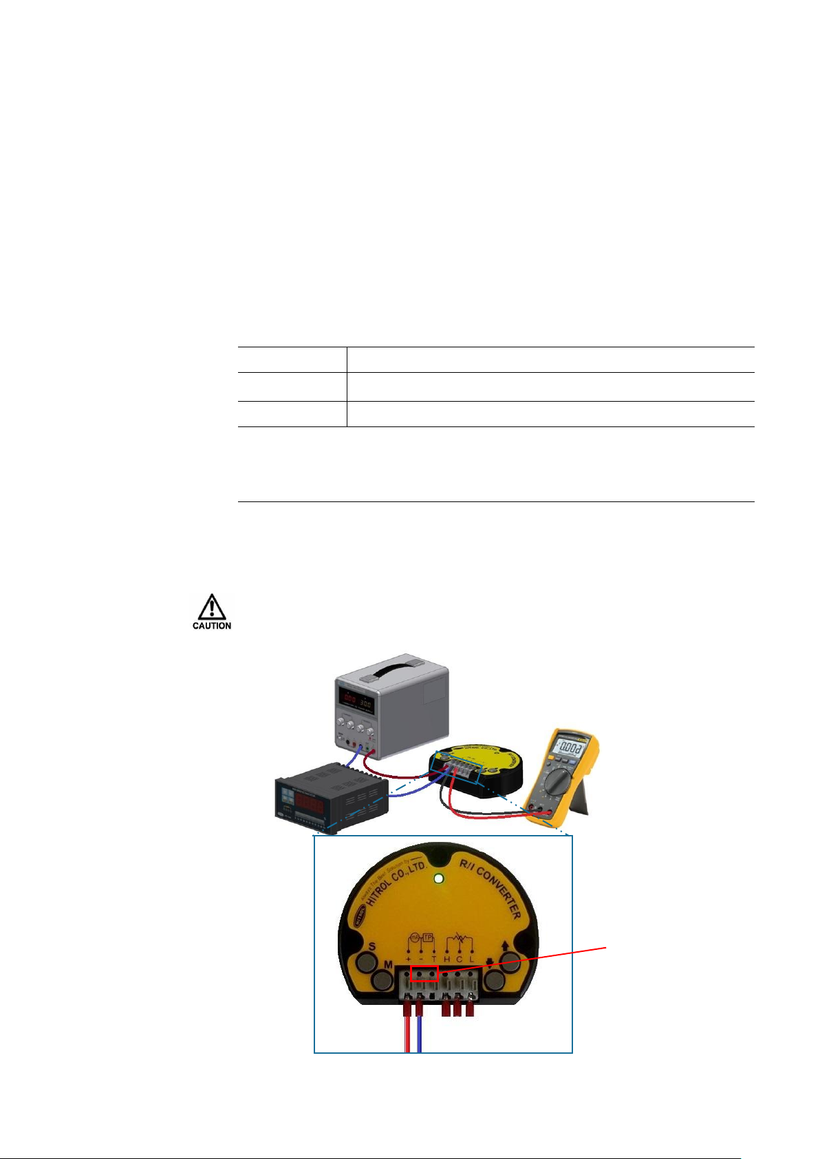
<Checking of the Transmission>
Check the output current of terminals T and –of the R/I converter using the digital multimeter.
※ The output current can be checked with the test points without opening its wire.
Sensor
Test Point
Indicator
R/I Converter
Power Supply
Digital Multimeter
After checking the sensor parts, the wrong connection of H, C, and L is the cause of the product failure.
HT-100F Series
HITROL CO., LTD. 9
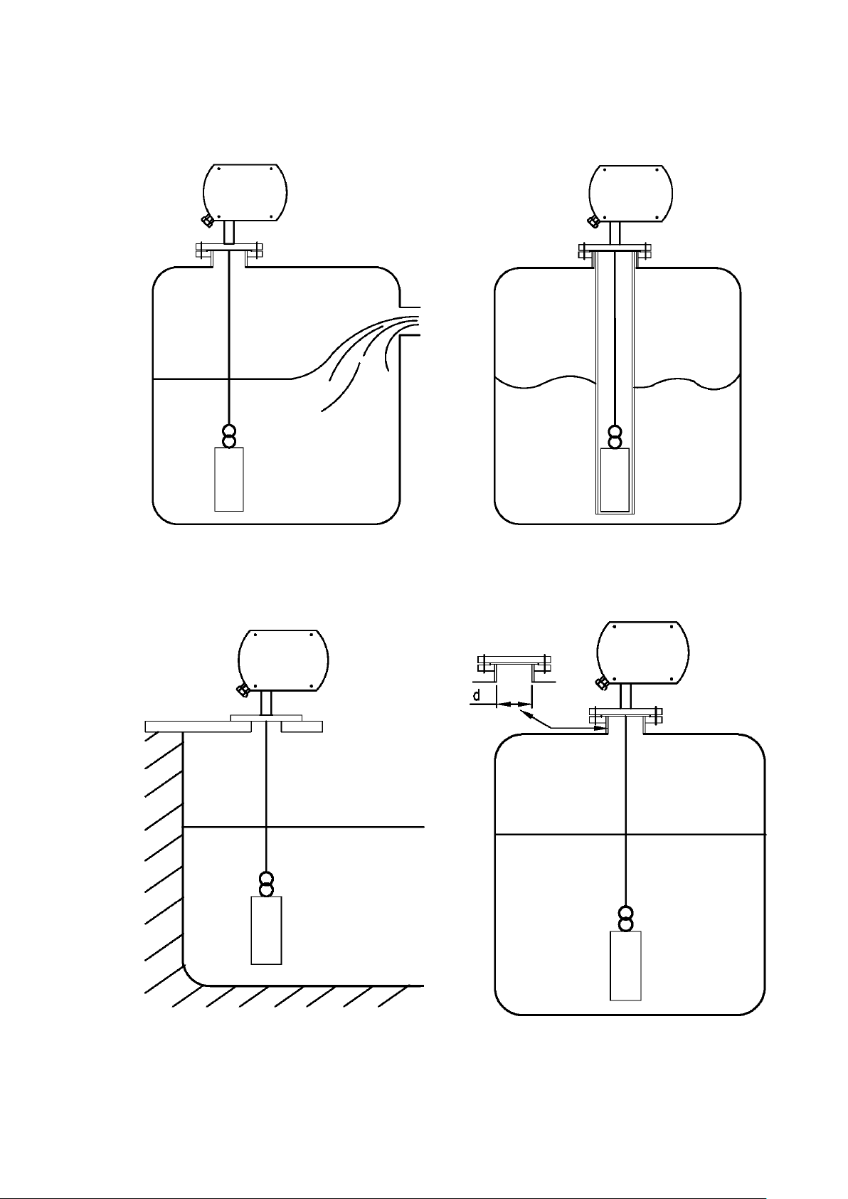
Attachment and
Cautions
If it is installed on the inlet, install a guide,
or make it distanced from the inlet to
prevent malfunction.
If the liquid flows or slashes,
use the protection pipe type.
Install it on the concrete wall as shown above.
“d” diameter requires a larger diameter than
float and straight piping.
HT-100F Series
HITROL CO., LTD. 10
Removal
Cautions
Cautions for
Installation
Cautions
for the Inserted
External Wire
Safety and
Environment
Marking
■Check the level and presence of liquid in the tank before removing it.
■Disconnect the power first.
■Connect flanges with same dimensions.
■Make sure to insert washers between bolts and nuts to prevent loosening.
■Make sure to insert gaskets between flanges.
■Make sure to install the product and to cover it before supplying power.
■Do not use it for any corrosive gas.
■Use the cable gland connection or metal pipe wiring for the inlet of wires.
Make sure it is not subject to any impact when moving it.
■Cautions
- Make sure to connect the product and container using the required tools.
- Do not apply large impact to the product.
■Disposal
- To dispose a waste product, separate the AMP and body first. It does not contain
any part that is harmful to the environment (e.g., mercury switch).
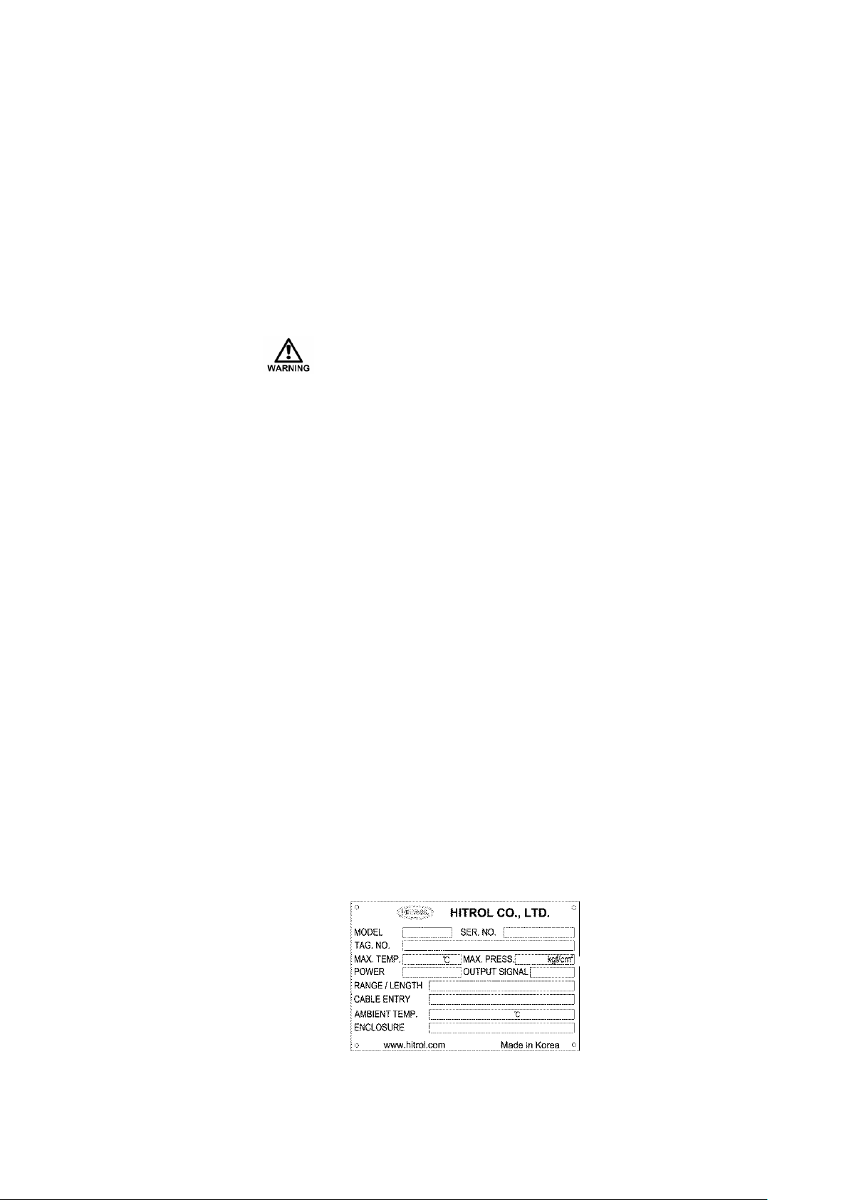
■Product Identification
The product identification mark is attached onto the housing and shows the model name, serial
number, working temperature, working pressure, and matters regarding output. The serial
number is a unique manufacturing number for the identification of products.

HT-100F Series
HITROL CO., LTD. 11
User
Training
Troubleshooting
Action
Type
Checks
Incorrect zero measurement range setting
Reset
Offset applied
Offset default
Loss of buoyancy or damage to the float
Replace the float
Damaged diode of the R/I converter
Replace the R/I converter
Type
Checks
Incorrect span measurement range setting
Reset
Offset applied
Offset default
Open low cable of sensor
Reconnect the sensor
Damaged diode of the R/I converter
Replace the R/I converter
Type
Checks
When the resistor of the sensor is seriously
damaged, resulting in a short circuit with
the pointer positioned on it
Replace the sensor PCB. (If the float is
out of the position, the output will
sharply rise or drop, leading to
measurement error.)
When the resistor of the sensor is seriously
damaged, resulting in an open circuit with
the pointer positioned on it
Replace the sensor PCB. (If the float is
out of the position, the output will
sharply rise or drop, leading to
measurement error.)
When the wire is not wound
Check if any foreign subsidence is in
the wire drum or if the spring is
damaged.
Type
Checks
Temporary over-measurement (approximately 10%)
and noise output shape due to over-current caused
when a diode of the R/I converter is damaged
Replace the R/I converter.
Output Current of 4mA or Less
Hunting of the Output
Holding of the Output Current
Understand the aforementioned, and never use it to measure any liquid that
exceeds 80°C. In addition, make sure that the ambient temperature of the housing
is maintained at −20°C ~ +60°C.
Output Current of 20mA or More

HT-100F Series
HITROL CO., LTD. 12
Warranty
and
Contact
Warranty and Service
This product is subject to a two-year warranty after shipment, and any unpaid service
will be provided for any damage found under normal operating conditions. If it is not
related to product failure, the service charge will be payable. You can request A/S at
our website or by contacting our headquarters.
Headquarters / Factory / Research Center
Address: HITROL CO., LTD., 141, Palhakgol-gil, Jori-eup, Paju-si, Gyeonggi-do, Korea
TEL.: 031-950-9700 (Headquarters and A/S)
FAX: 031-943-5600 (Headquarters and A/S)
Other manuals for HT-100F Series
2
This manual suits for next models
2
Table of contents
Other HITROL Transmitter manuals

HITROL
HITROL HT-100CT Series User manual

HITROL
HITROL HT-100F Series User manual

HITROL
HITROL HT-100R Series User manual

HITROL
HITROL HT-100F Series User manual

HITROL
HITROL HT-100R Series Configuration guide

HITROL
HITROL HT-100CT-2 Series User manual

HITROL
HITROL HTMF-MF User manual

HITROL
HITROL HT-100CT-2 Series User manual

HITROL
HITROL HT-100R Series User manual

HITROL
HITROL HT-100PT User manual


