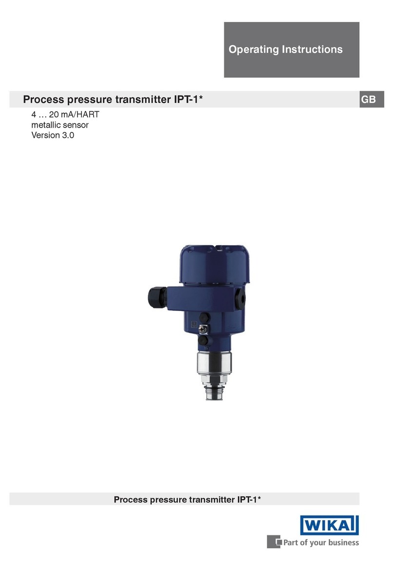
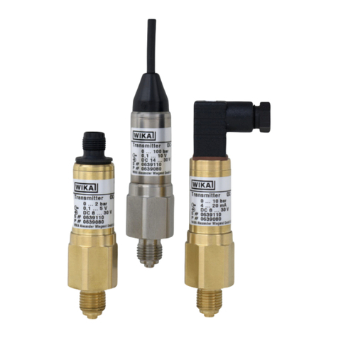
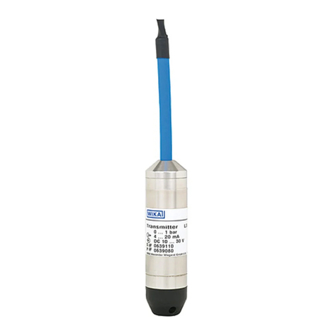
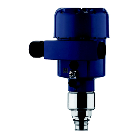
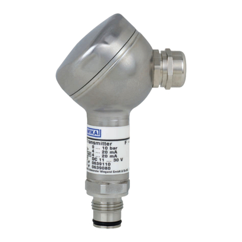
WIKA UPT-2 Series User manual

Operating instructions
Betriebsanleitung
EN
DE
Prozesstransmitter, Typ UPT-2x
Process transmitter, model UPT-2x
Plastic version Stainless steel version

2
14068347.04 09/2021 EN/DE
WIKA operating instructions process transmitter, model UPT-2x
EN
DE
© 2015 WIKA Alexander Wiegand SE & Co. KG
All rights reserved. / Alle Rechte vorbehalten.
WIKA®is a registered trademark in various countries.
WIKA®ist eine geschützte Marke in verschiedenen Ländern.
Prior to starting any work, read the operating instructions!
Keep for later use!
Vor Beginn aller Arbeiten Betriebsanleitung lesen!
Zum späteren Gebrauch aufbewahren!
Betriebsanleitung Typ UPT-2x Seite 69 - 133
Operating instructions model UPT-2x Page 3 - 68

3WIKA operating instructions, process transmitter, model UPT-2x
EN
14068347.04 09/2021 EN/DE
Contents
Contents
1. General information ...............................................6
2. Design and function ...............................................7
2.1 Design .................................................................7
2.2 Description..............................................................7
2.3 Scope of delivery.........................................................8
3. Safety ...........................................................9
3.1 Explanation of symbols....................................................9
3.2 Intended use ............................................................9
3.3 Personnel qualification ...................................................10
3.4 Handling of critical or hazardous media .....................................10
3.5 Labelling, safety marks...................................................11
4. Transport, packaging and storage ..................................12
4.1 Transport ..............................................................12
4.2 Packaging .............................................................12
4.3 Storage................................................................12
5. Commissioning, operation ........................................13
5.1 Mechanical mounting ....................................................13
5.1.1 Requirements for mounting point ....................................13
5.1.2 Mounting the process transmitter....................................13
5.2 Electrical installation .....................................................14
5.2.1 Safety instructions ................................................14
5.2.2 Requirements for connection cable ..................................15
5.2.3 Opening the case.................................................16
5.2.4 Shielding and grounding ...........................................17
5.2.5 Connection......................................................17
5.2.6 Pin assignments..................................................18
6. Display and operating unit, model DI-PT-U ...........................19
6.1 Design and description...................................................19
6.2 Accessing/exiting the operating menu.......................................19
6.3 Installation/Removal .....................................................20
6.4 To set the main display ...................................................21
6.5 Setting the additional display ..............................................22
7. Configuration without display and operating unit .....................23
7.1 Performing a mounting correction (offset)....................................23
7.2 Configuring via HARTinterface ...........................................24

4WIKA operating instructions, process transmitter, model UPT-2x
EN
14068347.04 09/2021 EN/DE
Contents
8. Configuration via display and operating unit .........................25
8.1 Configuring the measuring task . . . . . . . . . . . . . . . . . . . . . . . . . . . . . . . . . . . . . . . . . . . . 25
8.1.1 Configuring pressure measurement..................................25
8.1.2 Configuring level measurement .....................................26
8.1.3 Configuring the volume measurement ................................27
8.1.4 Characteristic curves..............................................30
8.2 Setting the units.........................................................32
8.2.1 Setting the pressure unit . . . . . . . . . . . . . . . . . . . . . . . . . . . . . . . . . . . . . . . . . . . 32
8.2.2 Set length unit (for level measurement) ...............................32
8.2.3 Setting the volume unit ............................................33
8.2.4 Setting the density unit and density value .............................34
8.2.5 Setting the temperature unit ........................................34
8.3 Scaling the measuring range ..............................................35
8.3.1 Performing a wet adjustment .......................................35
8.3.2 Performing a dry adjustment........................................36
8.4 Setting the mode ........................................................37
8.5 Mounting correction (offset) . . . . . . . . . . . . . . . . . . . . . . . . . . . . . . . . . . . . . . . . . . . . . . . 38
8.5.1 Performing a wet adjustment .......................................38
8.5.2 Performing a dry adjustment........................................38
8.6 Setting the dampening ...................................................39
8.7 Write protection .........................................................40
8.7.1 Activating/deactivating the write protection ............................40
8.7.2 Change PIN .....................................................40
9. Diagnostic functions .............................................41
9.1 Simulations ............................................................41
9.1.1 Performing a pressure simulation....................................41
9.1.2 Performing a current simulation .....................................41
9.2 Display/reset drag pointer.................................................42
9.2.1 Drag pointer Pmin/Pmax ........................................................... 42
9.2.2 Drag pointer PVmin/PVmax ..........................................43
9.2.3 Drag pointer Tmin/Tmax .............................................43
9.3 Display/reset operating time...............................................43
10. Detailed settings .................................................44
10.1 Setting the language .....................................................44
10.2 Marking the measuring point (TAG) .........................................44
10.2.1 Setting the TAG short..............................................44
10.2.2 Setting the TAG long ..............................................44
10.3 Setting the alarm signal ..................................................45
10.4 Setting the signal limits ...................................................45
10.5 Setting the contrast of the LC display .......................................46
10.6 Restoring factory setting..................................................46
10.7 Setting the HARTcommunication .........................................47

5WIKA operating instructions, process transmitter, model UPT-2x
EN
14068347.04 09/2021 EN/DE
Declarations of conformity can be found online at www.wika.com
Contents
10.7.1 Setting the short address (multidrop mode) ...........................47
10.7.2 Activate/deactivate constant current .................................47
11. Instrument information ...........................................48
11.1 Display measuring range .................................................48
11.2 Display date of manufacture...............................................48
11.3 Display firmware version..................................................48
11.4 Display serial number ....................................................48
12. Maintenance, cleaning and recalibration ............................49
12.1 Maintenance ...........................................................49
12.2 Cleaning...............................................................49
12.3 Recalibration ...........................................................49
13. Faults ..........................................................50
14. Dismounting, return and disposal ..................................51
14.1 Dismounting............................................................51
14.2 Return.................................................................51
14.3 Disposal ...............................................................51
15. Specifications ...................................................52
16. Accessories.....................................................61
Appendix 1: Menu tree, basic setting...................................62
Appendix 1: Menu tree, basic setting...................................63
Appendix 2: Menu tree, display........................................64
Appendix 2: Menu tree, display........................................65
Appendix 3: Menu tree, diagnositic ....................................66
Appendix 4: Menu tree, detail setup....................................67
Appendix 5 Menu tree, info ...........................................68

6WIKA operating instructions, process transmitter, model UPT-2x
EN
14068347.04 09/2021 EN/DE
1. General information
The process transmitter described in the operating instructions has been designed
and manufactured using state-of-the-art technology. All components are subject
to stringent quality and environmental criteria during production. Our management
These operating instructions contain important information on handling the instru-
ment. Working safely requires that all safety instructions and work instructions are
observed.
Observe the relevant local accident prevention regulations and general safety regula-
tions for the instrument's range of use.
The operating instructions are part of the product and must be kept in the immediate
vicinity of the instrument and readily accessible to skilled personnel at any time.
Skilled personnel must have carefully read and understood the operating instructions
prior to beginning any work.
The manufacturer's liability is void in the case of any damage caused by using the
product contrary to its intended use, non-compliance with these operating instruc-
-
cations to the instrument.
The general terms and conditions contained in the sales documentation shall apply.
Further information:
- Internet address: www.wika.de / www.wika.com
- Relevant data sheet: PE 86.05
- Application consultant: Tel.: +49 9372 132-0
Fax: +49 9372 132-406
info@wika.de

7WIKA operating instructions, process transmitter, model UPT-2x
EN
14068347.04 09/2021 EN/DE
2. Design and function
2.1 Design
2.2 Description
The process transmitter processes the prevailing pressure and converts it into a current
signal.This current signal can be used for the evaluation, control and regulation of the
process.
HART(option)
The instrument version with HARTcan communicate with a controller (master).
Measuring range scaling (turndown)
Process connection, thread Push-on cap
Product label
Sensor housing Ground screw, outside
Ex-relevant data Electrical connection, cable gland
Case head Second bore for cable gland (delivered sealed
with blind plug)

8WIKA operating instructions, process transmitter, model UPT-2x
EN
14068347.04 09/2021 EN/DE
2. Design and function
Display and operating unit (accessory)
The display and operating unit model DI-PT-U has a main and an additional display.
The main display and the additional display are able to be set in almost any way. In the
factory setting, the main display shows the pressure value of the output signal.
Adaptable to installation position
can be read irrespective of the installation position.
2.3 Scope of delivery
Pre-assembled process transmitter
Ordered accessories
Operating instructions
Measured value protocol
Cross-check scope of delivery with delivery note.
Displaceable display and operating unit
Rotatable case head

9WIKA operating instructions, process transmitter, model UPT-2x
EN
14068347.04 09/2021 EN/DE
3. Safety
3. Safety
3.1 Explanation of symbols
WARNING!
... indicates a potentially dangerous situation that can result in serious injury
or death, if not avoided.
CAUTION!
... indicates a potentially dangerous situation that can result in light injuries
or damage to property or the environment, if not avoided.
Information
trouble-free operation.
3.2 Intended use
The process transmitter measures gauge pressure, absolute pressure and vacuum.The
physical quantity pressure is converted into an electrical signal.
Only use the process transmitter in applications that lie within its technical performance
process connection must not be used with media which might damage the diaphragm of
the process connection.
The instrument has been designed and built solely for the intended use described here,
and may only be used accordingly.
The manufacturer shall not be liable for claims of any type based on operation contrary
to the intended use.

10 WIKA operating instructions, process transmitter, model UPT-2x
EN
14068347.04 09/2021 EN/DE
3. Safety
3.3 Personnel qualication
WARNING!
Risk of injury should qualication be insucient!
Improper handling can result in considerable injury and damage to property.
The activities described in these operating instructions may only be carried
out by skilled personnel who have the qualifications described below.
Skilled personnel
Skilled personnel are understood to be personnel who, based on their technical training,
knowledge of measurement and control technology and on their experience and
-
le of carrying out the work described and independently recognising potential hazards.
Special operating conditions require appropriate knowledge, e.g. of aggressive media,
compatibility of materials.
3.4 Handling of critical or hazardous media
WARNING!
liquids, and refrigeration plants, compressors, etc., in addition to all standard
regulations, the appropriate existing codes or regulations must also be follo-
wed.
WARNING!
Residual media in the dismounted process transmitter can result in a risk to
personnel, the environment and equipment.
Take sufficient precautionary measures.
For operation with oxygen as the medium to be measured, the process transmitter must
be oil and grease free and the liquid measurement transmission consist of inert oil, e.g.
halocarbon oil.
It is important to ensure that products which have been specially handled and packaged
protection with the application.

11WIKA operating instructions, process transmitter, model UPT-2x
EN
14068347.04 09/2021 EN/DE
3. Safety
3.5 Labelling, safety marks
Product label, process transmitter
Pin assignment Model code
Supply voltage Date of manufactureYYYY-MM
Output signal
Measuring range S# Serial no.
Model P# Product no.
Product label, display and operating unit
The Ex marking is not valid if the display and operating unit is used in conjunction with
process transmitters without Ex marking.
Date of manufactureYYYY-MM
Model code
Model
S# Serial no.
Ex marking
Symbols
Before mounting and commissioning the instrument, ensure you read the
operating instructions!
Output signal
Supply voltage

12 WIKA operating instructions, process transmitter, model UPT-2x
EN
14068347.04 09/2021 EN/DE
3. Safety/4.Transport, packaging and storage
Fullment of special recommendations
NE21
and laboratory technology
NE32
NE43
digital transmitters with analogue output
NE53 -
ments
NE107
4. Transport, packaging and storage
4.1 Transport
Check the process transmitter for any damage that may have been caused by transport.
Obvious damage must be reported immediately.
4.2 Packaging
Do not remove packaging until just before mounting.
Keep the packaging as it will provide optimum protection during transport (e.g. change
in installation site, return for calibration).
4.3 Storage
Permissible conditions at the place of storage:
Humidity: 35 ... 93 % relative humidity (non-condensing)
Avoid exposure to the following factors:
Proximity to hot objects, when permissible storage temperature is exceeded by
radiation.
Mechanical vibration, mechanical shock (putting it down hard), when the permissible
Soot, vapour, dust and corrosive gases.
for installation in or mounting to equipment in explosive atmospheres.
-
tions listed above. If the original packaging is not available, then store the instrument in a
container that is similar to the original packaging, so that the instrument can't be scrat-
ched and is protected against damage if dropped.

13WIKA operating instructions, process transmitter, model UPT-2x
EN
14068347.04 09/2021 EN/DE
5. Commissioning, operation
The process transmitter should only be commissioned and operated by skilled personnel.
For high-pressure versions, also note the additional instructions for highest
pressure (article number: 14375527).
5.1 Mechanical mounting
5.1.1 Requirements for mounting point
The process transmitter can be adjusted to the installation site.
Operating elements can be accessed following the mounting.
Ambient and medium temperatures remain within the permitted limits.
Consider possible restrictions on the ambient temperature range caused by mating
connector used.
Protect the process transmitter from heat sources (e.g. pipes or tanks).
Additional for instruments with cooling element:
Mount the process transmitter as horizontally as possible and ensure an unhindered
air circulation at the cooling element.
The cooling element should have as little soiling as possible, otherwise the cooling
action cannot be guaranteed. Ensure as much space as possible so that the cooling
element can be cleaned.
5.1.2 Mounting the process transmitter
Sealing
Parallel threads
Seal the sealing face
sealings.
per EN 837 per DIN EN ISO 1179-2
(formerly DIN 3852-E)
Tapered threads
Wrap threads with sealing materials,
e.g. PTFE tape.
NPT, R and PT

14 WIKA operating instructions, process transmitter, model UPT-2x
EN
14068347.04 09/2021 EN/DE
5. Commissioning, operation
Screwing in
CAUTION!
Improper mounting
Through improper mounting, the process transmitter can be damaged.
Tighten the process transmitter using the spanner flats.
Do not tighten using the sensor housing or the case head.
Use a suitable open-ended spanner.
Do not cross the threads.
Screw the process transmitter into the mounting location with a spanner using the
The tightening torque depends on the dimensions of the process connection and the
sealing used (form/material).
For information on tapped holes and welding sockets, see Technical informa-
tion IN 00.14 at www.wika.com.
5.2 Electrical installation
5.2.1 Safety instructions
Only connect with the voltage disconnected.
If any overvoltage is expected, install surge protection devices.
Exposed cables must not run close to bare metal components. Maintain a minimum
Ensure that the cables are properly installed and the cable gland or plug connections
are securely closed and sealed.
Sensor housing
Case head

15WIKA operating instructions, process transmitter, model UPT-2x
EN
14068347.04 09/2021 EN/DE
5. Commissioning, operation
5.2.2 Requirements for connection cable
Use and assemble connection cable that is suitable for the application. For cables
Where there is electromagnetic radiation above the test values per EN 61326, a
shielded connection cable must be used.
When using an M12 x 1 (4-pin) circular connector, the mating connector is supplied
by the customer. Ensure the matching design from the connector manufacturer.
Electrical connections
Cable gland M20 x 1.5 and spring-
loaded terminals
Ingress protection: IP66/67
Wire cross-section: max. 2.5 mm2(AWG 14)
Single cable: 0.13 ... 2.5 mm²
End splices: 0.13 ... 1.5 mm²
For cable diameters outside of 5 ... 12 mm
Angular connector DIN 175301-803A
with mating connector
Ingress protection: IP65
Wire cross-section: max. 1.5 mm²
Circular connector M12 x 1 (4-pin)
without mating connector
Ingress protection: IP65
Ground screw, inside 0.13 ... 2.5 mm²
Ground screw, outside 0.13 ... 4 mm²

16 WIKA operating instructions, process transmitter, model UPT-2x
EN
14068347.04 09/2021 EN/DE
5. Commissioning, operation
5.2.3 Opening the case
CAUTION!
Ingress of moisture
Moisture can destroy the process transmitter.
Protect the opened process transmitter against moisture.
Plastic case
Screw off the case head cover by hand and pull out the display and operating unit or
push-on cap.
Stainless steel case
Screw off the case head cover by means of an open-ended spanner and pull out the
display and operating unit or push-on cap.

17WIKA operating instructions, process transmitter, model UPT-2x
EN
14068347.04 09/2021 EN/DE
5. Commissioning, operation
5.2.4 Shielding and grounding
The process transmitter must be shielded and grounded in accordance with the ground-
ing concept of the plant.
Connect the cable shield with the equipotential bonding.
Connect the process connection or the external grounding screw with the equipoten-
tial bonding
5.2.5 Connection
1. Pass the connection cable through the cable gland and connect it.
Ensure that no moisture can enter at the cable end.
2. Tighten the cable gland.
Recommended tightening torque 1.5 Nm
Check that the seals are correctly seated in order to guarantee the ingress
protection.
3. Perform a mounting correction.
®
4. Attach the push-on cap or display and operating unit and screw the case head cover
tight down to the stop.
5. With instruments with stainless steel cases, ensure that the sealing ring is located
correctly within the sealing groove on the cover (no gap between cover and case).

18 WIKA operating instructions, process transmitter, model UPT-2x
EN
14068347.04 09/2021 EN/DE
5. Commissioning, operation
5.2.6 Pin assignments
Pin assignmentOutlet for connection cable
Cable gland Negative power supply terminal –
Process connection Ground screw, inside (GND)
Positive power supply terminal +
Spring-loaded terminal
Angular connector DIN 175301-803 A
1
2
3
+1
–2
Shield GND
Circular connector M12 x 1 (4-pin)
43
12
+1
–3
Shield 4
The shield connection is located on the inside of the instrument.

19WIKA operating instructions, process transmitter, model UPT-2x
EN
14068347.04 09/2021 EN/DE
6. Display and operating unit, model DI-PT-U
6.1 Design and description
The display and operating unit model DI-PT-U is available as an accessory.
can be read, whether the process transmitter is mounted laterally or upside down.
The Ex marking on the rear side is not valid if the display and operating unit is used in
conjunction with process transmitters without Ex marking.
Description
6.2 Accessing/exiting the operating menu
If after 3 min. no entry is made, the menu will automatically be exited and the
last set display mode will be activated.
display for 2 seconds, and the previous menu will be accessed.
Additional display
Unit
Main display
Trend display
Bar graph with over/under limit arrows
and drag pointer function

20 WIKA operating instructions, process transmitter, model UPT-2x
EN
14068347.04 09/2021 EN/DE
6. Display and operating unit, model DI-PT-U
6.3 Installation/Removal
CAUTION!
Ingress of moisture.
Moisture can destroy the process transmitter.
Protect the opened process transmitter against moisture.
Close the case head tightly.
1. Plastic case
Stainless steel case
means of an open-ended spanner
2. Installation
Pull out the push-on cap and attach
the display and operating unit into any
Removal
Pull out the display and operating unit
and attach the push-on cap
3. Screw on the case head cover.
Ensure that the case head is tightly
closed.
This manual suits for next models
2
Table of contents
Languages:
Other WIKA Transmitter manuals