PROEL Xeos User manual

USER’S MANUAL
MANUALE UTENTE
proelgroup.com

2FIG. 1
speaker max rotation
170mm
[6.7"]
speaker max rotation
192mm
[7.6"]
speaker max rotation
230mm
[9.1"]
200mm
[7.9"]
243mm
[9.6"]
290mm
[11.4"]
130mm
[5.1"] 182mm
[7.2"] 220mm
[8.7"]
100mm
[3.9"]
163mm
[6.4"]
196mm
[7.7"]
fix screw max
Ø10mm
[Ø0.4"]
fix screw max
Ø10mm
[Ø0.4"]
wires max
Ø14mm
[Ø0.6"]
screw
Ø6mm
[Ø0.2"]
screw
Ø6mm
[Ø0.2"]
wires
Ø8mm
[Ø0.3"]
fix screw max
Ø10mm
[Ø0.4"]
wires max
Ø14mm
[Ø0.6"]
fix screw max
Ø10mm
[Ø0.4"]
XE35T
NOTE: the drill drawing shown is for vertical mounting
Always check that the fixing plugs choosen are suitable to the type of wall
and that they can hold up the weight of the speaker safely.
Recommended screws for the fixing plugs are:
Ø 6mm [1/4"] for XE35T
Ø 8mm [5/16"] for XE55T
Ø 10mm [13/32"] for XE65T
XE55T XE65T
WALL DRILLING - FORATURAMURO
NOTA: il disegno della foratura è per il montaggio verticale
Accertarsi sempre che i tasselli scelti siano adatti al tipo di parete e siano
in grado di sostenere il peso dell'altoparlante in sicurezza.
Le viti raccomandate per i tasselli sono:
Ø 6mm per XE35T
Ø 8mm per XE55T
Ø 10mm per XE65T
speaker max rotation
360mm
[14.2"]
speaker max rotation
338mm
[13.3"]
182mm
[7.2"]
screw
Ø6mm
[Ø0.2"]
screw
Ø6mm
[Ø0.2"]
49mm
[1.9"]
XE55T
WALL DRILLING - SNBK or SNWH optional accessory
FORATURAMURO - accessorio opzionale SNBK o SNWH
65mm
[2.6"]
243mm
[9.6"]
max horizontal aiming rotation is 90° left or right
max vertical aiming rotation is 25° down and 12° up
This accessory can be used
only for XE55T model.
Questo accessorio può essere usato
solo per il modello XE55T.

3
FIG. 2 - 3 - 4
100 / 70 V line
AUP240L
The TOTAL POWER of all the speakers must be less or equal
to the power of the amplifier.
La SOMMA delle potenze degli altoparlanti deve essere
inferiore o uguale alla potenza dell’amplificatore.
CONSTANT VOLTAGE LINE
LOW IMPEDANCE SYSTEM
+
+
-+- +-+-
-
+-+-
+
-+
-
LLRR
ACDT90V
(for other AVL equipment see AVL system
catalogue at proelgroup.com)
(for other AVL equipment see AVL system
catalogue at proelgroup.com)
Speakers and amplifier power capability must be
approximately the same for the specified impedance.
Altoparlanti e amplificatore devono avere approssimativamente
la stessa potenza per l’impedenza specificata.
RED / ROSSO BLACK / NERO
RED / ROSSOBLACK / NERO

4english
This marking shown on the product or its literature, indicates that it should not be disposed with other household wastes
at the end of its working life. To prevent possible harm to the enviroment or human health from uncontrolled waste
disposal, please separate this from other types of wastes and recycle it responsibly to promote the sustainable reuse of
material resources. Household users should contact either the retailer where they purchased this product, or their local
government oce, for details of where and how they can take this item for environmentally safe recycling. Business users
should contact their supplier and check the terms and conditions of the purchase contract. This product should not be mixed
with other commercial wastes for disposal.
The exclamation point within an equilateral triangle is intended to alert the user to the presence of important operating
and maintenance (servicing) instructions in the literature accompanying the appliance.
SAFETY AND PRECAUTIONS
• CAUTION - Before using this product read carefully the following safety instructions. Take a look of this manual entirely and
preserve it for future reference.
When using any electric product, basic precautions should always be taken, including the following:
– To reduce the risk, close supervision is necessary when the product is used near children.
– Protect the apparatus from atmospheric agents and keep it away from water, rain and high humidity places.
– This product should be site away from heat sources such as radiators, lamps and any other device that generate heat.
– Care should be taken so that objects and liquids do not go inside the product.
IN CASE OF FAULT
• In case of fault or maintenance this product should be inspected only by qualied service personnel when:
– Liquids have spilled inside the product.
– The product has fallen and been damaged.
– The product does not appear to operate normally or exhibits a marked change in performance.
• Do not operate on the product, it has no user-serviceable parts inside, refer servicing to an authorized maintenance centre.
CE CONFORMITY
• Proel products comply with directive 89/336/EEC (EMC) and following modications 92/31/EEC and 93/68/EEC, as stated in EN
55103-1 and EN 55103-2 standards and with directive 73/23/EEC (LVD) and following modications 93/68/EEC, as stated in EN
60065 standard.
PACKAGING, SHIPPING AND COMPLAINT
• This unit package has been submitted to ISTA 1A integrity tests. We suggest you control the unit conditions immediately after
unpacking it.
• If any damage is found, immediately advise the dealer. Keep all unit packaging parts to allow inspection.
• Proel is not responsible for any damage that occurs during shipment.
• Products are sold“delivered ex warehouse” and shipment is at charge and risk of the buyer.
• Damages to unit should be immediately notied to forwarder. Each complaint for manumitted package should be done within
eight days from receipt.
WARRANTY AND PRODUCTS RETURN
• Proel products have operating warranty and comply their specications, as stated by manufacturer.
• Proel warrants all materials, workmanship and proper operation of this product for a period of two years from the original
date of purchase. If any defects are found in the materials or workmanship or if the product fails to function properly during
the applicable warranty period, the owner should inform about these defects the dealer or the distributor, providing receipt or
invoice of date of purchase and defect detailed description. This warranty does not extend to damage resulting from improper
installation, misuse, neglect or abuse. Proel S.p.A. will verify damage on returned units, and when the unit has been properly
used and warranty is still valid, then the unit will be replaced or repaired. Proel S.p.A. is not responsible for any "direct damage"
or "indirect damage" caused by product defectiveness.
INSTALLATION AND DISCLAIMER
• Proel products have been expressly designed for audio application, with signals in audio range (20Hz to 20kHz). Proel has no
liability for damages caused in case of lack of maintenance, modications, improper use or improper installation non-applying
safety instructions.
• The installation of these speakers is provided for indoors, in case of use outdoors be sure that the speakers are installed correctly
in a safe location protected from wind, rain and umidity.
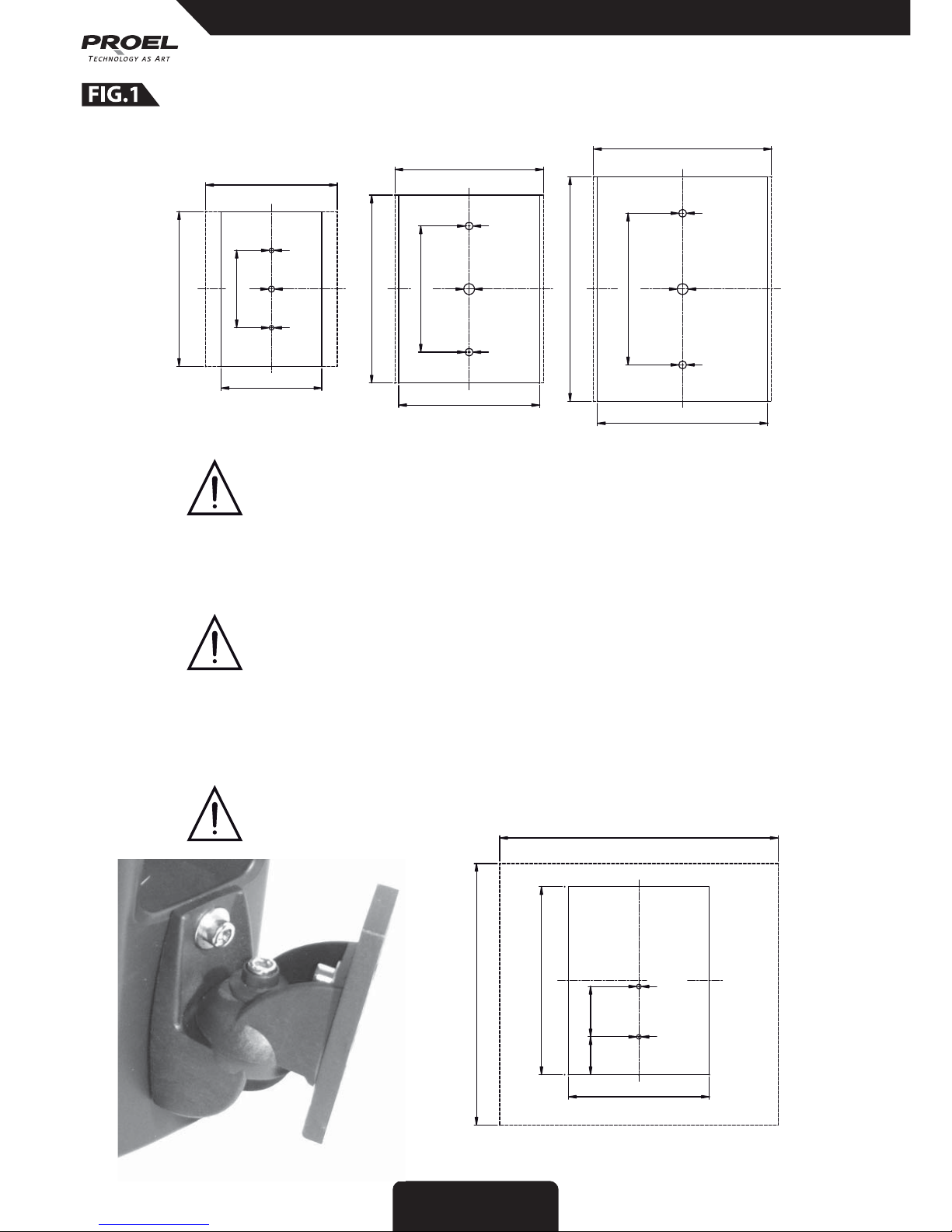
• The installation of these speakers is provided for wall mounting by means of specic wall brackets able to support their weight.
Fix the wall bracket to the wall using appropriate xings.
• Always know the working load limit of the structure supporting the loudspeakers. Always make sure that the xings minimum
rating is at least ve times the actual load, speakers and wall brackets.
• Locate the speakers as far away as possible from radio or television receivers or other sensitive equipment. These speakers
have a strong magnetic eld which can induce hum and noise into unshielded devices that are located nearby with consequent
deterioration of reception of image and sound.
• Proel S.p.A. declines any liability for damages to objects or persons caused by lacks of maintenance, improper use, installation
not performed with safety precautions and at the state of the art.

5
Introduction
XEOS is a series of speakers designed specically for installed sound applications.
All of the models in the XEOS range utilize high-denition dome tweeters and high-eciency woofers,
providing superior quality, full-range sound for a wide scope of installations where the sound system must
blend perfectly into any environment.
The three dierent surface-mount models available suit any kind of installed sound system, from paging and
background music in small-size environments, to full-range sound in bars, department stores and outdoor
venues, through to complex systems in large areas such as shopping halls and airports.
Technical Specication
Model XE35T XE55T XE65T
Speaker coax 3.5” woofer - 1” tweeter coax 5” woofer - 1” tweeter coax 6.5” woofer - 1” tweeter
Nominal Impedance 8 ohm 8 ohm 8 ohm
Max power rms/peak 15 W / 30 W 30 W / 60 W 40 W / 80 W
Nom. line power 1 / 2 / 4 / 7.5 / 15 W 1 / 2 / 5 / 10 / 30 W 2 / 5 / 10 / 20 / 40 W
70 V line impedance 4900/2450/1225/653/327 Ω 4900/2450/980/490/163 Ω 2450/980/490/245/123 Ω
100 V line impedance 10000/5000/2500/1333/667 Ω 10000/5000/2000/1000/333 Ω 5000/2000/1000/500/250 Ω
Line Input Voltage 70 / 100 V 70 / 100 V 70 / 100 V
Frequency Response 70 Hz - 20 KHz 70 Hz - 20 KHz 50 Hz - 20 KHz
S.P.L. 1 W / 1 m 85 dB 87 dB 87 dB
Dimensions 130 x 198 x 130 mm 181 x 240 x 172 mm 217 x 288 x 204 mm
Weight 1.8 Kg [3.97 lb] 2.7 Kg [5.95 lb] 3.7 Kg [8.16 lb]
INSTALLATION instructions valid for all models
1. WALL DRILLING AND FIXING THE BRACKET TO THE WALL
The wall drilling must be done as shown in the drawing for the model to be installed. Check if the
loudspeaker has enough space to orientate it in the desired direction and check that the xing plugs
choosen are suitable to the type of wall and that they can hold up the weight of the speaker safely, then x
the bracket to the wall.
2. CONNECTION
Connect the speaker to the amplier following the correct polarity: Red (+) positive / Black (-) negative.
Following the same polarity for the whole audio system is very important for obtaining an optimal acoustical
result (see FIG. 2 - 3 - 4).
3. SPEAKER MOUNTING
Plug in the speaker into the bracket, aim it to sound a zone, then screw tightly the locking screws of the
cabinet.
ALWAYS MAKE SURE THAT LOUDSPEAKER IS PROPERLY LOCKED TO ITS BRACKET.
4. VOLTAGE SETTING
If the loudspeaker is connected to a constant voltage distributed line, set the switch to the correct voltage
(70V is usually the standard for America, 100V is usually the standard for Europe).
Always check that the line power amplier is set for the same voltage.
5. LINE POWER SETTING OR LOW IMPEDANCE SETTING
Use the switch (1) to set the constant voltage line and the switch (2) to set the max power sent to the
loudspeaker: this setting depends on the max output power of amplier and on the number of speakers
connected, according to the rule shown in FIG.3.
The same switch (2) can be used for selecting 8 Ωimpedance, so the line transformer is excluded and the
loudspeaker can be connected to a low impedance amplier (see the LOW IMPEDANCE SYSTEM connection
in FIG.4). In this case power capability of speakers and amplier must be approximately the same for the
specied impedance.
CAUTION: the speaker can be damaged if it is erroneously set to 8 Ωand connected to a distributed
line.
english

6italiano
Il marchio riportato sul prodotto o sulla documentazione indica che il prodotto non deve essere smaltito con altri riuti
domestici al termine del ciclo di vita. Per evitare eventuali danni all’ambiente si invita l’utente a separare questo prodotto
da altri tipi di riuti e di riciclarlo in maniera responsabile per favorire il riutilizzo sostenibile delle risorse materiali. Gli
utenti domestici sono invitati a contattare il rivenditore presso il quale è stato acquistato il prodotto o l’ucio locale
preposto per tutte le informazioni relative alla raccolta dierenziata e al riciclaggio per questo tipo di prodotto. Gli utenti
aziendali sono invitati a contattare il proprio fornitore e vericare i termini e le condizioni del contratto di acquisto. Questo
prodotto non deve essere smaltito unitamente ad altri riuti commerciali.
Il punto esclamativo in un triangolo equilatero intende avvertire l'utilizzatore per la presenza di importanti istruzioni per
l'utilizzo e la manutenzione nella documentazione che accompagna il prodotto.
AVVERTENZE PER LA SICUREZZA
• ATTENZIONE - Prima di utilizzare il prodotto, si prega di leggere attentamente le seguenti istruzioni per la sicurezza. Prendere
visione del manuale d’uso e conservarlo per successive consultazioni:
– In presenza di bambini, controllare che il prodotto non rappresenti un pericolo.
– Posizionare l’apparecchio al riparo dagli agenti atmosferici e a distanza di sicurezza dall’acqua, dalla pioggia e dai luoghi ad
alto grado di umidità.
– Collocare o posizionare il prodotto lontano da fonti di calore quali radiatori, griglie di riscaldamento e ogni altro dispositivo
che produca calore.
– Evitare che qualsiasi oggetto o sostanza liquida entri all’interno del prodotto.
IN CASO DI GUASTO
• In caso di guasto o manutenzione questo prodotto deve essere ispezionato da personale qualicato quando:
– Sostanze liquide sono penetrate all’interno del prodotto.
– Il prodotto è caduto e si è danneggiato.
– Il prodotto non funziona normalmente esibendo una marcato cambio di prestazioni.
• Non intervenire sul prodotto. Rivolgersi a un centro di assistenza autorizzato Proel.
CONFORMITÀ CE
• I Prodotti Proel sono conformi alla direttiva 89/336/EEC (EMC) e successive modiche 92/31/EEC e 93/68/EEC, secondo gli
standard EN 55103-1 ed EN 55103-2 ed alla direttiva 73/23/EEC (LVD) e successive modiche 93/68/EEC, secondo lo standard EN
60065.
IMBALLAGGIO, TRASPORTO E RECLAMI
• L’imballo è stato sottoposto a test di integrità secondo la procedura ISTA 1A. Si raccomanda di controllare il prodotto subito
dopo l’apertura dell’imballo.
• Se vengono riscontrati danni informare immediatamente il rivenditore. Conservare l’imballo completo per l’ispezione.
• Proel declina ogni responsabilità per danni causati dal trasporto.
• Le merci sono vendute “franco nostra sede” e viaggiano sempre a rischio e pericolo del distributore.
• Eventuali avarie e danni dovranno essere contestati al vettore. Ogni reclamo per imballi manomessi dovrà essere inoltrato entro
8 giorni dal ricevimento.
GARANZIE E RESI
• I Prodotti Proel sono provvisti della garanzia di funzionamento e di conformità alle proprie speciche, come dichiarate dal
costruttore.
• La garanzia di funzionamento è di 24 mesi dopo la data di acquisto. I difetti rilevati entro il periodo di garanzia sui prodotti
venduti, attribuibili a materiali difettosi o difetti di costruzione, devono essere tempestivamente segnalati al proprio rivenditore
o distributore, allegando evidenza scritta della data di acquisto e descrizione del tipo di difetto riscontrato. Sono esclusi dalla
garanzia difetti causati da uso improprio o manomissione. Proel SpA constata tramite verica sui resi la difettosità dichiarata,
correlata all’appropriato utilizzo, e l’eettiva validità della garanzia; provvede quindi alla sostituzione o riparazione dei prodotti,
declinando tuttavia ogni obbligo di risarcimento per danni diretti o indiretti eventualmente derivanti dalla difettosità.
INSTALLAZIONE E LIMITAZIONI D’USO
• I Prodotti Proel sono destinati esclusivamente ad un utilizzo specico di tipo sonoro: segnali di ingresso di tipo audio (20Hz-
20kHz). Proel declina ogni responsabilità per danni a terzi causati da mancata manutenzione, manomissioni, uso improprio o
installazione non eseguita secondo le norme di sicurezza.
• L'installazione di questi altoparlanti è prevista per uso interno, in caso di utilizzo all'esterno assicurarsi che gli altoparlanti siano
installati correttamente in un luogo sicuro e protetto dal vento, pioggia e umidità.
• L'installazione di questi altoparlanti è prevista a parete tramite specici supporti in grado di sostenere il proprio peso. Fissare i
supporti da parete usando solo ssaggi appropriati e specici per quella parete.
• Non superare il limite di carico della struttura che sosterrà gli altoparlanti. Assicurarsi che tutti i ssaggi di sostegno siano in
grado di sopportare un peso almeno 5 volte superiore al carico degli altoparlanti inclusi i supporti.
• Installare questi altoparlanti il più lontano possibile da radioricevitori e televisori. Un altoparlante installato in prossimità di
questi apparati può causare interferenza e rumore con conseguente degrado della ricezione di immagini e suoni.
• Proel declina ogni responsabilità per danni a terzi causati da mancata manutenzione, manomissioni, uso improprio o
installazione non eseguita secondo le norme di sicurezza e a regola d'arte.

7
Introduzione
XEOS è una serie di diusori progettati in modo specico per installazioni sse.
Tutti i modelli XEOS utilizzano tweeter a cupola ad alta denizione e woofer ad elevata ecienza, per
garantire prestazioni acustiche superiori e un suono full-range di elevata qualità, per un'ampia gamma di
installazioni in cui il sistema di diusione deve fondersi perfettamente con l'ambiente.
I tre diversi modelli surface-mount sono adatti alla diusione di annunci e musica di sottofondo in piccoli
ambienti, ad un suono completo in bar, supermercati e ambienti aperti, no a sistemi complessi in spazi di
grandi dimensioni come centri commerciali ed aeroporti.
Caratteristiche Tecniche
Modello XE35T XE55T XE65T
Altoparlante coax 3.5” woofer - 1” tweeter coax 5” woofer - 1” tweeter coax 6.5” woofer - 1” tweeter
Impedenza nominale 8 ohm 8 ohm 8 ohm
Potenza max rms/peak 15 W / 30 W 30 W / 60 W 40 W / 80 W
Potenza nom. linea 1 / 2 / 4 / 7.5 / 15 W 1 / 2 / 5 / 10 / 30 W 2 / 5 / 10 / 20 / 40 W
Impedenza linea 70 V 4900/2450/1225/653/327 Ω 4900/2450/980/490/163 Ω 2450/980/490/245/123 Ω
Impedenza linea 100 V 10000/5000/2500/1333/667 Ω 10000/5000/2000/1000/333 Ω 5000/2000/1000/500/250 Ω
Tensione di ingresso 70 / 100 V 70 / 100 V 70 / 100 V
Risposta in frequenza 70 Hz - 20 KHz 70 Hz - 20 KHz 50 Hz - 20 KHz
S.P.L. 1 W / 1 m 85 dB 87 dB 87 dB
Dimensioni 130 x 198 x 130 mm 181 x 240 x 172 mm 217 x 288 x 204 mm
Peso 1.8 Kg 2.7 Kg 3.7 Kg
Istruzioni di INSTALLAZIONE valide per tutti i modelli
1. FORATURA PARETE E MONTAGGIO SUPPORTO ALLA PARETE
Eseguire la foratura della parete secondo il disegno per il modello da installare. Accertarsi che l'altoparlante
disponga dello spazio necessario al suo orientamento e che i tasselli scelti siano adatti al tipo di parete e
siano in grado di sostenere il peso dell'altoparlante in sicurezza, quindi ssare il supporto alla parete.
2. COLLEGAMENTO
Collegare l'altoparlante all'impianto rispettando la polarità indicata: Rosso (+) positivo / Nero (-) negativo.
Rispettare la medesima polarità in tutto il sistema di amplicazione è molto importante al ne di ottenere
un comportamento acustico ottimale (vedi FIG. 2 - 3 -4).
3. FISSAGGIO ALTOPARLANTE
Inserire l'altoparlante nel supporto, puntarlo verso la zona da sonorizzare quindi avvitare accuratamente
le viti di blocco.
ACCERTARSI SEMPRE CHE L'ALTOPARLANTE SIA CORRETTAMENTE BLOCCATO AL SUPPORTO.
4. IMPOSTAZIONE LINEA
Se l'altoparlante è collegato ad una linea distribuita a tensione costante, accertarsi che il selettore sia
posizionato sulla corretta tensione (70V è solitamente usato come standard in America, 100V è solitamente
usato come standard in Europa).
Accertarsi sempre che l'amplicatore collegato sulla linea sia impostato alla medesima tensione.
5. IMPOSTAZIONE POTENZA LINEA O BASSA IMPEDENZA
Impostare tramite l'interuttore (1) la tensione della linea distribuita e tramite il selettore (2) impostare
la potenza da inviare all'altoparlante: l'impostazione è in funzione della potenza dell'amplicatore e del
numero di altoparlanti collegati secondo la formula riportata in FIG.3.
Lo stesso selettore può essere utilizzato per selezionare l'impedenza di 8 Ω, in modo da escludere il
trasformatore di linea e collegare l'altoprlante ad un amplicatore a bassa impedenza (vedi LOW IMPEDANCE
SYSTEM nella FIG.4). In tal caso la scelta della potenza dell'amplicatore deve approssimativamente
coincidere con la potenza degli altoparlanti impiegati per l'impedenza specicata.
ATTENZIONE: se un altoparlante viene erroneamente impostato su 8 Ωe collegato ad una linea
distribuita si può causare la rottura dell'altoparlante stesso.
italiano

proelgroup.com
PROEL S.p.A.
(World Headquarters - Factory)
Via alla Ruenia, 37/43
64027 Sant’Omero (TE) - ITALY
Tel. +39 0861 81241
Fax +39 0861 887862
rev. 51/10 code 96MAN0044
This manual suits for next models
4
Table of contents
Languages:
Other PROEL Speakers manuals

PROEL
PROEL FLASH8A V2 User manual

PROEL
PROEL FLASH15A V2 User manual

PROEL
PROEL EIKON series User manual

PROEL
PROEL CSE06T User manual

PROEL
PROEL FREE6LT User manual

PROEL
PROEL WD10P User manual

PROEL
PROEL CS3TW User manual

PROEL
PROEL LT812A User manual

PROEL
PROEL CO40HQ User manual

PROEL
PROEL WEDGE WD10A User manual