PROEMION CANlink mobile 3600 Launch Kit User manual

CANlink mobile 3000 Quick Start Guide

CANlink mobile Quick Start
1. About this Quick Start Guide. . . . . . . . . . . . . . . . . . . . . . . . . . . . . . . . . . . . . . . . . . . . . . . . . . . . . . . . . . . . . . . . . . . . 1
1.1. Further information . . . . . . . . . . . . . . . . . . . . . . . . . . . . . . . . . . . . . . . . . . . . . . . . . . . . . . . . . . . . . . . . . . . . . . . 1
1.2. Onboarding best practice . . . . . . . . . . . . . . . . . . . . . . . . . . . . . . . . . . . . . . . . . . . . . . . . . . . . . . . . . . . . . . . . . . 2
2. Provisioning and GoLive . . . . . . . . . . . . . . . . . . . . . . . . . . . . . . . . . . . . . . . . . . . . . . . . . . . . . . . . . . . . . . . . . . . . . . . 2
3. Unpacking the Launch Kit . . . . . . . . . . . . . . . . . . . . . . . . . . . . . . . . . . . . . . . . . . . . . . . . . . . . . . . . . . . . . . . . . . . . . . 3
4. Connecting the Device to a PC . . . . . . . . . . . . . . . . . . . . . . . . . . . . . . . . . . . . . . . . . . . . . . . . . . . . . . . . . . . . . . . . . . 5
5. Installing Proemion Configurator. . . . . . . . . . . . . . . . . . . . . . . . . . . . . . . . . . . . . . . . . . . . . . . . . . . . . . . . . . . . . . . . . 6
6. Installing Demo Configuration . . . . . . . . . . . . . . . . . . . . . . . . . . . . . . . . . . . . . . . . . . . . . . . . . . . . . . . . . . . . . . . . . . . 7
7. Perform a functional Test . . . . . . . . . . . . . . . . . . . . . . . . . . . . . . . . . . . . . . . . . . . . . . . . . . . . . . . . . . . . . . . . . . . . . . 7
8. Check and adjust DataPortal. . . . . . . . . . . . . . . . . . . . . . . . . . . . . . . . . . . . . . . . . . . . . . . . . . . . . . . . . . . . . . . . . . . . 8

1. About this Quick Start Guide
This document is part of the CANlink mobile 3600 series documentation and provides information regarding
installation and configuration of the CANlink mobile 3600 and the first steps with the Launch Kit.
The document is intended for qualified technicians and electricians with advanced knowledge in electrical engineering
and field bus systems, allowing them to assess the risks and hazards of operating the device and to integrate it into
systems with components of other manufacturers.
It provides a quick overview of how to set the CANlink mobile into operation with the DataPlatform when receiving the
first device together with our Launch Kit. We also assume, that a DataPlatform account setup has been ordered and
the technical contact person at the customer has received the information about the setup completion.
Figure 1. General system overview
1.1. Further information
For a comprehensive information about the several components, please refer to these manuals:
•CANlink mobile Device Manual
•DataPortal User Manual
•PDC Manual
CANlink mobile 3000 Quick Start Guide

1.2. Onboarding best practice
Due to our experience in integrating a telematics solution into a fleet of machines, we would like to recommend the
following best practice for the initial start-up of a CANlink mobile together with your data platform access:
1. Create a laboratory setup with the device and the launch kit or starter kit.
2. Configure the device for your application with our Proemion Configurator software.
3. Activate the device.
4. Create a PDC file to display the recorded signals on the data portal and assign it to the device via the
management portal.
5. Check the connection of the device to the data platform and the data transmission and display in your
laboratory setup e.g., with simulated CAN messages.
6. Install the device in a real machine and wire it as described in the device manual.
7. Now check the functionality on the real machine.
8. First roll out the new setup on a smaller set of pilot machines to prove the solution before using it in the
complete fleet.
This document will guide you through the steps necessary for your initial setup.
2. Provisioning and GoLive
Provisioning allows you to make a machine with a telematics unit installed available on the DataPortal. The machine
will be visible and during the process you can assign a model and change the machine name, serial number and
PIN/VIN.
GoLive is the automated activation of a communication unit (CU) after Provisioning. Once the CU has been activated,
it is authorized to connect to the DataPlatform and transfer data.
1. Login to the Proemion DataPortal User Manual
2. Login with your username and password
3. Provision the CANlink mobile to make it visible on your DataPortal account as described in the DataPortal ¬
Provisioning
4. Use DataPortal ¬ GoLive to activate the device and permit DataPortal communication
INFORMATION
For the first time login, the initial password must be set. Please use the “Forgot password” function
on DataPortal.
Enter the username which was provided along with the account setup confirmation email.
Another email with instructions on how to reset the password will be sent to your email address.
INFORMATION
Please note that the activation of the embedded SIM card can take up to 24 hours in exceptional
cases.
CANlink mobile 3000 Quick Start Guide
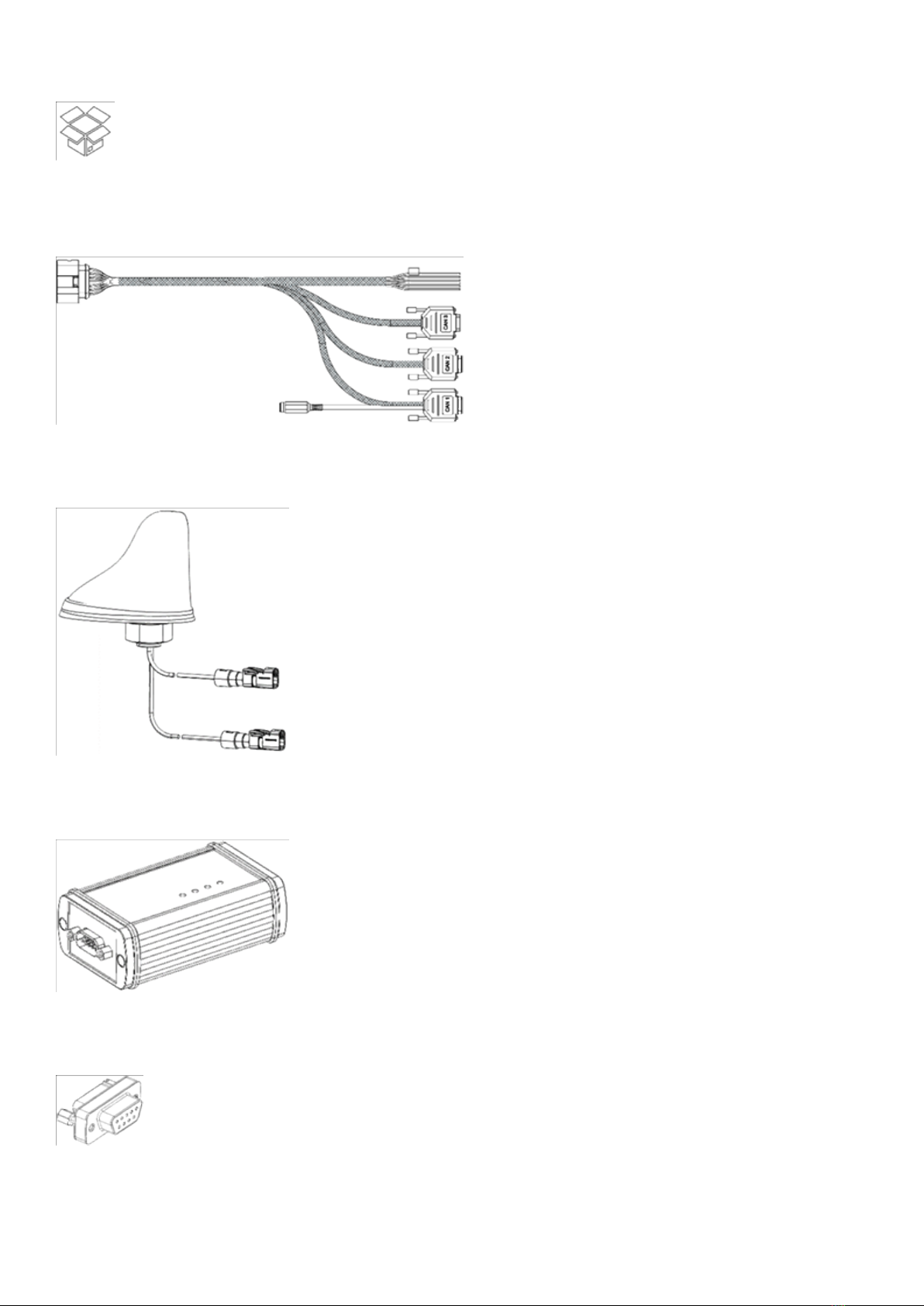
3. Unpacking the Launch Kit
The CANlink mobile 3600 Launch Kit (253000176) consists of the following components
CLM 3600 Starter Cable (136000202)
Figure 2. CLM 3600 Starter Cable
Antenna LTE GNSS DA 3M0 FAKRA-D FAKRA-C FAR (157000109)
Figure 3. Antenna LTE GNSS DA 3M0 FAKRA-D FAKRA-C FAR
CANview USB (253001014)
Figure 4. CANview USB
CAN bus terminator D-Sub/D-Sub, 120¬ (157000033)
Figure 5. CAN Bus Terminator D-Sub/D-Sub, 120¬
USB Cable for CANview USB (136000119)
CANlink mobile 3000 Quick Start Guide
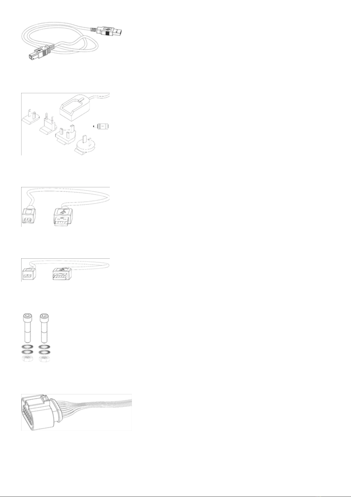
Figure 6. USB Cable (CANview USB)
Power Supply Unit With Set Of Connectors (US, EU, UK, AU) and adapter (257004007)
Figure 7. Power Supply Unit With Set Of Connectors (US, EU, UK, AU) and adapter
USB Cable (Debugging, Diagnosis), Micro USB Type B (136000138)
Figure 8. USB Cable (Debugging, Diagnosis), Micro USB Type B
USB Cable (Bootloader, Firmware Update), Micro USB Type A (136000199)
Figure 9. USB cable (Bootloader, Firmware Update), Micro USB Type A
Assembly Set M5 Housing GH1208 (141000017)
Figure 10. Assembly Set M5 Housing GH1208
Cable MTII 14pin Code1 14open 2m (136000198)
Figure 11. Cable MTII 14pin Code1 14open 2m
CANlink mobile 3000 Plug-Kit (132600031)
CANlink mobile 3000 Quick Start Guide

Figure 12. Connector MT
Figure 13. Contacts (14 pcs)
Figure 14. Single Wire Seal (14 pcs)
Figure 15. Cavity Blanking Plug (14 pcs)
Product Information leaflet (144000133)
Figure 16. Product Information Leaflet
For further information regarding the components of the Launch Kit, please refer to the CANlink mobile Device Manual
¬ Launch Kit.
4. Connecting the Device to a PC
Connect the CANlink mobile 3600 to your PC as shown in the image below. Please use the components from the
Launch Kit.
CANlink mobile 3000 Quick Start Guide
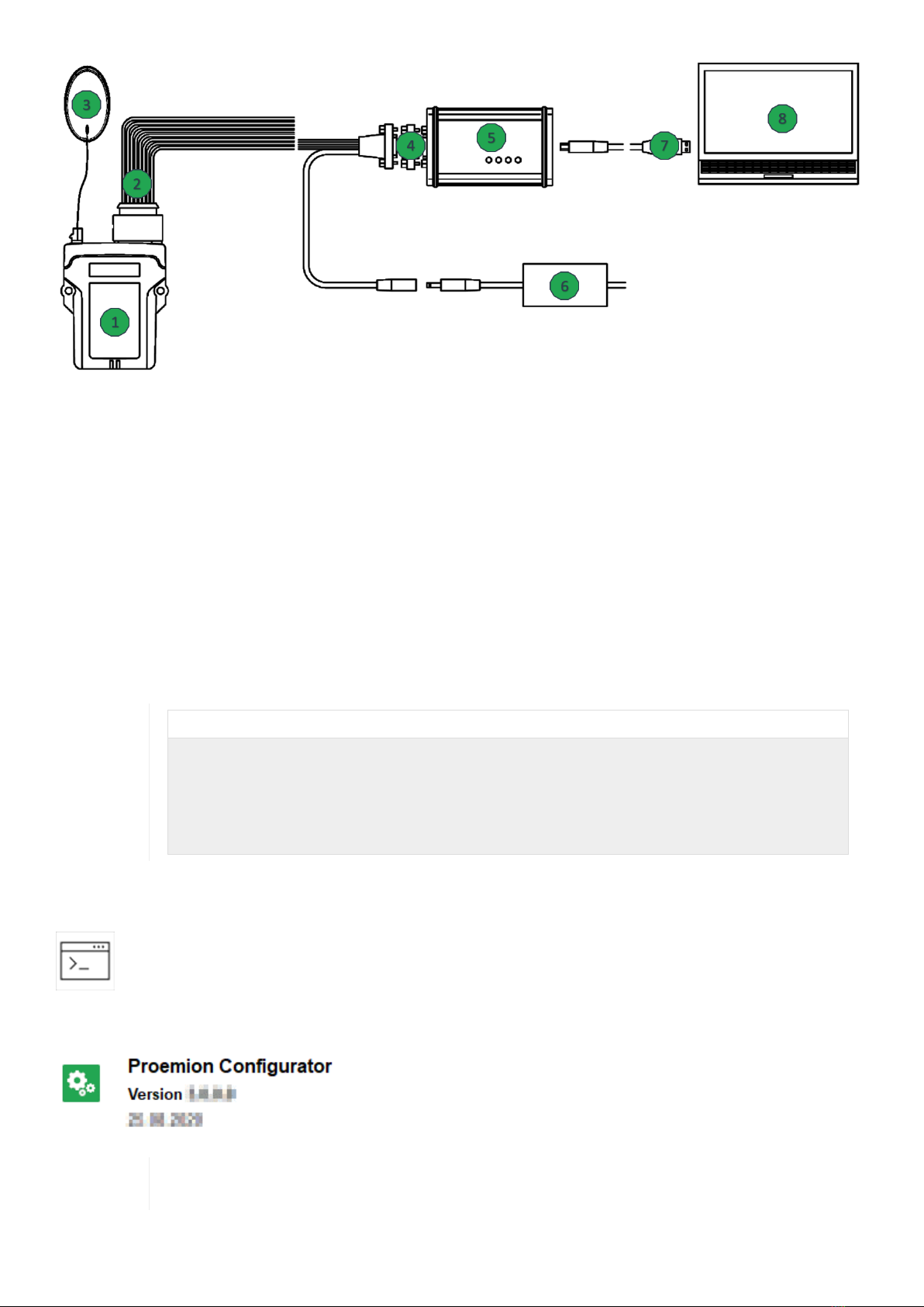
Figure 17. Connecting The Device With A PC
1. CANlink mobile
2. CLM 3600 Starter cable
3. Antenna
4. CAN bus termination resistor 120 Ohm
5. CANview USB
6. Power supply
7. USB cable
8. PC
Please also refer to CANlink mobile Device Manual ¬ Connecting the Device.
INFORMATION
Please be aware that the CANlink mobile 3600 is not equipped with an integrated CAN bus
termination resistor. The displayed labatory setup above will work with just one CAN bus
termination resistor. When doing the system integration at the intended machine, it must be
ensured that the CAN bus is terminated with a CAN bus termination resistor of 120 Ohm at each
end of the CAN bus line. Please also refer to CANlink mobile Device Manual ¬ Can Bus
Termination.
5. Installing Proemion Configurator
Install the latest version of the Proemion Configurator from our Download Center.
In case of problems, the Connectivity Check utility can be used to check the connectivity of our
software tools with our services from your site’s network.
CANlink mobile 3000 Quick Start Guide

6. Installing Demo Configuration
A demo configuration for your CANlink mobile type is available at our Download Center
Open the corresponding demo configuration file named like clm36xx_Proemion_DemoConfig.DOD with the
Proemion Configurator software.
Install the configuration to the device as described in CANlink mobile Device Manual ¬ Configuration Update.
For further information on how to create a customized device configuration, please refer to the CANlink mobile Device
Manual ¬ Customtizing Demo Configuration File.
7. Perform a functional Test
This work step is aimed to simulate the configured CAN messages with a CAN Monitor software and its corresponding
CAN-PC gateway.
In this case you can use the RM CAN Device Monitor and the CANview USB for a functional test. Other CAN-PC
gateways and software may also work for this test.
Install the RM CAN Device Monitor which can be found in the Download Center at folder
157002059_PROEMIONtools_CD\05_Utilities\01_RM CAN Device Monitor.
Ensure that the device is wired according to chapter Connecting the Device to a PC.
Cyclic send a few sample CAN messages which are configured within the installed configuration of the CANlink mobile
in the Receive CAN Messages section.
Table 1. The following messages can be used for test:
J1939-PGN SPN CAN ID Type DLC Data Bytes Signal
61444 190 0x18F00400 Ext 8 00 00 00 80 25 00 00
00 = 1200 rpm
CANlink mobile 3000 Quick Start Guide

J1939-PGN SPN CAN ID Type DLC Data Bytes Signal
65262 110 0x18FEEE00 Ext 8 7D 00 00 00 00 00 00
00 = 85°C
Check the status LEDs of the CANlink mobile. The device should be powered on and indicate reception of CAN
messages. Please also refer to CANlink mobile Device Manual ¬ Indicator Elements.
In case that there is access to a real machine which is also transmitting the configured CAN messages, the CANlink
mobile 3600 can be also connected to the corresponding CAN bus.
Notice
CAN bus errors possible!
Please make sure that the configured CAN baud rate is matching the controller CAN baud rate of
the machine.
8. Check and adjust DataPortal
In the last step you check and adjust the DataPortal appearance for your machine’s signals.
•Login to your DataPortal account
•Ensure that the customer default model with the demo PDC is assigned to the machine
•Check the displayed signals for your Machine within the DataPortal.
•Modify the machine details page with customized widgets according to your preferences. Please also refer to
the DataPortal User Manual ¬ Widget Introduction/Catalog.
To get further information about creation and adjustment of customized PDC files, please refer to the DataPortal User
Manual ¬ Administration Menu ¬ PDC Management.
Version: 11.0.310
CANlink mobile 3000 Quick Start Guide
This manual suits for next models
1
Table of contents
Other PROEMION Network Hardware manuals

PROEMION
PROEMION CANlink wireless 3000 Series Application guide

PROEMION
PROEMION CANlink wireless 4000 Series Application guide

PROEMION
PROEMION CANlink wireless 3000 Series Application guide

PROEMION
PROEMION CANlink wireless 3000 Series Application guide

PROEMION
PROEMION CANlink wireless 3000 Series Application guide


