PROFAX WP220 User manual
WELDING POSITIONER
Model: WP220
WP350
WP500
(WP220/WP350) (WP500)
Operation Manual

Table of contents
1. Safety warnings…………………………….….……….3
2. Appearance of the machine…….……………..………7
3. Main specification……...............….………….……….9
4. Operation instruction.....................……………...........9
5. Electrical Drawing............................……. ..............11
6. Exploded drawing and parts list…………………..…..14
2

Save this manual!
You will need the manual for the safety warnings and
precautions, assembly instructions, operating and
maintenance procedures, parts list and diagram. Keep
your invoice with this manual. Keep the manual and
invoice in a safe and dry place for future reference.
Safety Warnings and Precautions
WARNING: FAILURE TO FOLLOW THESE RULES MAY
RESULT IN SERIOUS PERSONAL INJURY As with all
machinery there are certain hazards involved with
operation and use of the machine. Using the machine with
respect and caution will considerably lessen the
possibility of personal injury. However, if normal safety
precautions are overlooked or ignored, personal injury to
the operator may result.
Read all instructions before operation!
1.1 MACHINERY GENERAL SAFETY WARNINGS
Keep work area clean. Cluttered areas invite injuries.
Observe work area conditions. Do not use
machines or power tools in damp or wet locations.
Don’t expose to rain. Keep work area well lighted. Do
not use electrically powered tools in the presence of
flammable gases or liquids.
Keep children away. Children must never be allowed
in the work area. Do not let them handle machines,
tools, or extension cords.
3

Store idle equipment. When not in use, tools must be
stored in a dry location to inhibit rust. Always lock up
tools and keep out of reach of children.
Do not force tool. It will do the job better and more
safety at the rate for which it was intended. Do not use
inappropriate attachments in an attempt to exceed the
tool capacity.
Use the right tool for the job. Do not attempt to force
a small tool or attachment to do the work of a large
industrial tool. Do not use a tool for a purpose for
which it was not intended.
Dress properly. Do not wear loose clothing of jewelry
as they can be caught in moving parts. Protective,
electrically non-conductive clothes and non-skid
footwear are recommended when working. Wear
restrictive hair covering to contain long hair.
Use eye and ear protection. Always wear ISO
approved impact safety goggles. Wear a full-face
shield if you are producing metal filings or wood chips.
Wear an ISO approved dust mask or respirator when
working around metal, and chemical dusts and mists.
Do not overreach. Keep proper footing and balance
at all times. Do not reach over or across running
machine.
Maintain tools with care. Keep tools sharp and clean
for better and safer performance. Follow instructions
for lubricating and changing accessories. The handles
must be kept clean, dry, and free from oil and grease
at all times.
Stay alert. Watch what you are doing; use common
4

sense. Do not operate any tool when you are tried.
Check for damaged parts. Before using any tool, any
part that appears damaged should be carefully
checked to determine that it will operate properly and
perform its intended function. Check for alignment and
binding of moving parts; any broken parts or mounting
fixtures; and any other condition that may affect proper
operation. Any part that is damaged should be
properly repaired or replaced by a qualified technician.
Guard against electric shock. Prevent body contact
with grounded surfaces such as pipes, radiators,
ranges, and refrigerator enclosures.
Replacement parts and accessories. When
servicing, use only identical replacement parts. Use of
any other parts will void the warranty. Only use
accessories intended for use with this tool. Approved
accessories are available from the distributor.
Do not operate tool if under the influence of
alcohol or drugs. Read warning labels on
prescriptions to determine if your judgment of reflexes
are impaired while taking drugs. If there is any doubt,
do not operate the tool.
Don’t leave machine until it comes to a complete
stop.
Never leave the machine running while unattended.
Machine shall be shut off whenever it is not in
operation.
Make sure machine is disconnected from power
supply while making maintenance, adjustment or
repair
5

Ground all machines. Always make sure your
machine is well connected to the earth. It may reduce
electric shock hazards.
Don’t use in dangerous environment. Don’t use
power machine in damp or wet locations, or expose
them to rain. Keep work area well lighted
Stop machine before servicing and when changing
accessories.
1.2 WARNING BEFORE OPERATION
Before start the machine, make sure the machine be
anchored to floor firmly, to avoid the machine turn on
one’s side.
Before fix workpiece, make sure worktable horizontal.
Before start the machine, make sure the adjusting
clamp handle locked firmly, to avoid worktable
deflection during working.
Before running worktable, make sure the thrust ball
bearing under worktable is lubricated sufficiently.
Do not touch the electrical switch with wet hands.
Before power on, make sure there is no any person
nor obstacles in the dangerous area of the rotating
machine.
Make sure workpiece be fixed firmly before rotate
worktable.
When adjust angle of worktable, make sure workpiece
be fixed firmly by external force, to avoid injury of
operator.
No part of body is allowed to close during rotating.
Overload is not allowed.
Keep table horizontal when move the machine.
6
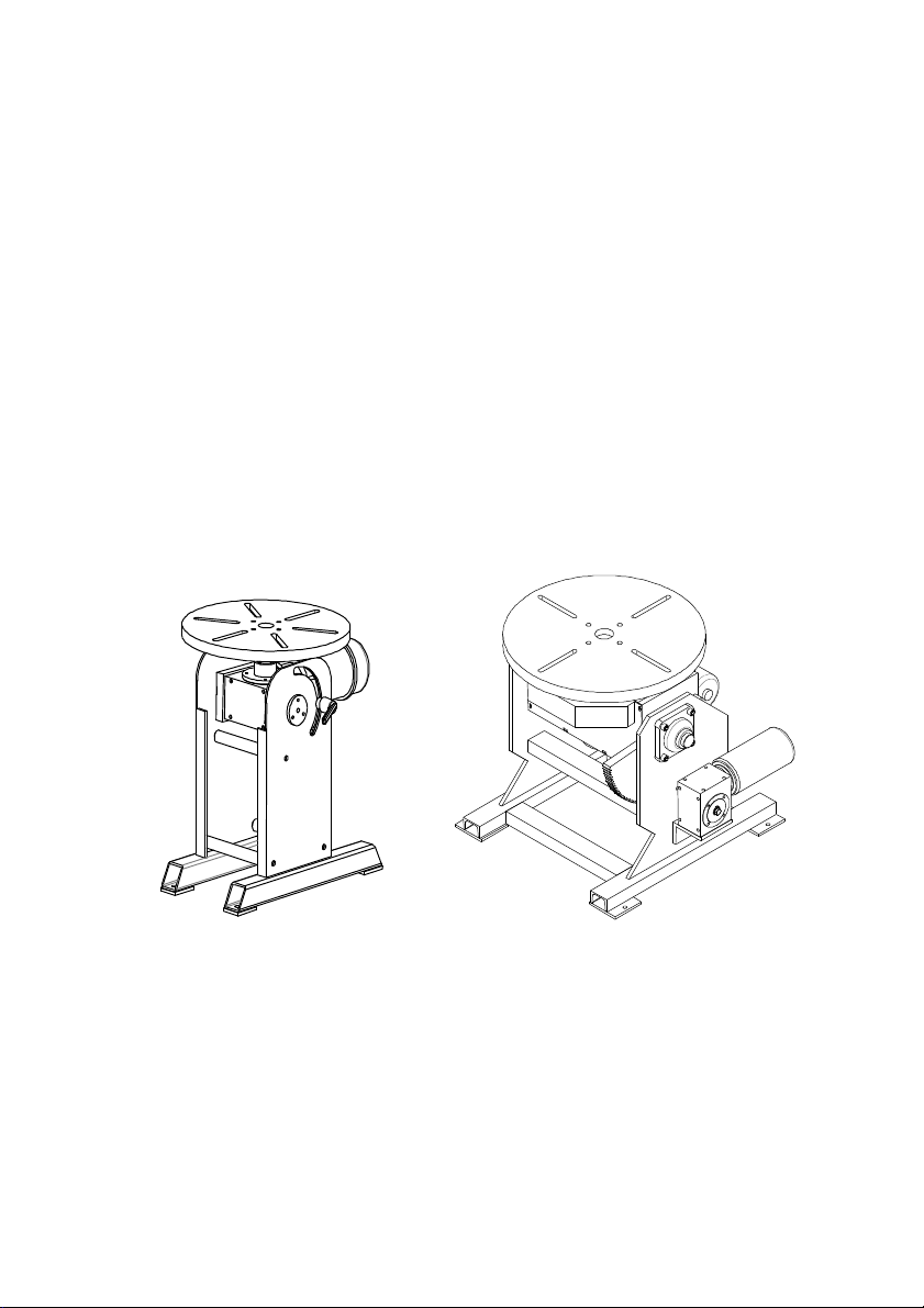
2. Appearance of the machine
2.1 WP220
Note: The warning and instructions contained in this
instruction manual cannot cover all possible conditions
and situations that may occur when using this product.
It must be understood that common sense and caution
are factors, which cannot be built into this product.
These factors must be supplied by the person whom
operating this piece of equipment.
Electric
box
7

2.2 WP350
2.3 WP500
Electric
box
8

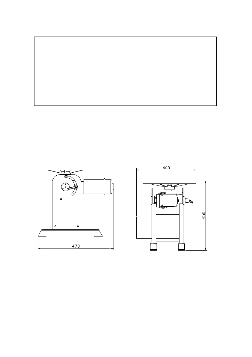
3. Main specification
Item No. 378381 378382 378383
Model WP220 WP350 WP500
Horizontal
loading capacity
220 kg 350 kg 500 kg
Vertical loading
capacity 100 kg 120 kg 250 kg
Table dia. 330 mm 330 mm 550 mm
Table height 450 mm 480 mm 660 mm
Rotation Speed
0-5 rpm 0-5 rpm 0-5 rpm
Tilt angle 0-135° 0-135° -45°~90°
Tilt by Manual Manual Electric
Rotation motor
125 W 125 W 400 W
Packing size 64x49x63 cm
64x44x63 cm 82x73x71 cm
N.W./G.W. 34/48 kg 38/52 kg 220/245 kg
4. Operation instruction
4.1 Adjust of WP220/WP350
4.1.1 Adjust revolve of worktable
Power on the machine, the worktable revolves when
step on foot switch; stop revolve when loosen foot
switch.
The worktable’s positive and negative rotation can be
controlled by the rotary knob on top of electric box.
Turn knob clockwise, worktable rotate positive;
9
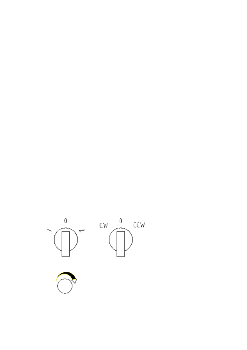
turn knob anticlockwise, worktable rotate negative;
When turn knob to middle tap position, then power off
and stop work.
While worktable rotates smooth and steady, it’s speed
can be adjusted by the rotary knob on bottom of
electric box. Turn knob clockwise, speed up; turn
knob anticlockwise, speed down.
4.1.2 Adjust angle of worktable
Hold up worktable firmly when machine come to a full
stop (can be done by several people together when
workpiece is heavy).
Turn the locking hand shank upward, adjust angle of
worktable by manual.
Turn the locking hand shank downward after
adjustment, make sure lock firmly, then finish angle
adjustment.
4.2 Adjust of WP500
(Adjust revolve of worktable)
10
This manual suits for next models
2
Table of contents
Other PROFAX Welding Accessories manuals


