ProFire PF2200-SB User manual

DOC-001041 / v1.0
PF2200-SB
INSTALLATION GUIDE
FIRMWARE VERSION SB 1.3.1

DOC-001041 / v1.0
2
TABLE OF CONTENTS
INTRODUCTION......................................................................................................................................................... 4
CERTIFICATIONS ........................................................................................................................................................ 4
SAFETY INFORMATION .............................................................................................................................................. 5
GENERAL WARNINGS................................................................................................................................................. 5
INSTALLATION WARNINGS......................................................................................................................................... 5
EXPLOSION HAZARD WARNINGS................................................................................................................................ 6
INSTALLATION........................................................................................................................................................... 6
ENCLOSURE SPECIFICATIONS...................................................................................................................................... 7
MOUNTING CONSIDERATIONS................................................................................................................................... 8
ACCESSIBILITY ........................................................................................................................................................... 8
SECURITY .................................................................................................................................................................. 8
OPERATOR SAFETY .................................................................................................................................................... 8
PERFORMANCE ......................................................................................................................................................... 8
PRODUCT PROTECTION.............................................................................................................................................. 9
CONDUIT/CABLE/ENVIRONMENTAL CONSIDERATIONS............................................................................................... 9
USER INTERFACE CARD ELECTRICAL RATINGS............................................................................................................ 10
BMS CARD............................................................................................................................................................... 11
BMS CARD SPECIFICATIONS.......................................................................................................................................................11
BMS CARD ELECTRICAL RATINGS.............................................................................................................................. 12
WIRING................................................................................................................................................................... 14
POWER ................................................................................................................................................................... 14
VALVES PILOT VALVE OUTPUTS (PILOT 1 & PILOT 2).................................................................................................. 14
MAIN VALVE OUTPUTS (SSV) ................................................................................................................................... 14
COIL........................................................................................................................................................................ 16
SINGLE ROD CONFIGURATION.................................................................................................................................. 16
FLAME DETECTION WIRE LENGTH LIMITATIONS........................................................................................................ 16
INSTALLATION DIAGRAMS ....................................................................................................................................... 17
PRE / POST-ASSEMBLY CHECKLIST............................................................................................................................ 19
COMMISSIONING .................................................................................................................................................... 20
TIME AND DATE SETTING .................................................................................................................................................... 20

DOC-001041 / v1.0
3
STARTING/STOPPING .............................................................................................................................................. 20
NAVIGATION ....................................................................................................................................................................... 21
MENU MAP............................................................................................................................................................. 21
SYSTEM CONFIGURATION........................................................................................................................................ 22
PASSWORDS........................................................................................................................................................................ 23
INTERFACING ......................................................................................................................................................................24
SETTINGS MODIFICATION ........................................................................................................................................ 25
DROP-DOWN MENU CHANGES................................................................................................................................. 26
NUMERICAL SETTING CHANGES .................................................................................................................................................. 27
SYSTEM SCREEN ...................................................................................................................................................... 28
TEMPERATURES .................................................................................................................................................................. 28
INPUTS................................................................................................................................................................................. 29
OUTPUTS............................................................................................................................................................................. 29
FLAME DIAGNOSTICS ..........................................................................................................................................................30
POWER ................................................................................................................................................................................30
RUN TIMES .......................................................................................................................................................................... 31
MODBUS ............................................................................................................................................................................. 31
KEYPAD................................................................................................................................................................................ 32
EVENT LOG .......................................................................................................................................................................... 32
DATA LOGGING ................................................................................................................................................................... 33
STATUS PRIORITY ................................................................................................................................................................ 33
ABOUT.................................................................................................................................................................................34
RESET SETTINGS .................................................................................................................................................................. 34
BACKUP &RESTORE SETTINGS............................................................................................................................................ 35
START-UP CHECKLIST ............................................................................................................................................... 36
OPERATION............................................................................................................................................................. 36
INSTALLATION TROUBLESHOOTING.......................................................................................................................... 37
PREVENTATIVE MAINTENANCE ................................................................................................................................ 39
CLEANING ............................................................................................................................................................... 39
REPLACEMENT PARTS.............................................................................................................................................. 39
DOC-001041 / v1.0
4
INTRODUCTION
This guide includes information on the installation of the PF2200 burner management system. PROFIRE
recommendations and requirements for installation.
This document covers:
•Product Overview.
•Safety and Warnings.
•Mounting Considerations.
•Wiring Guidelines.
•Post Installation Checklist
•Profire Recommendation and Requirements.
For troubleshooting any Alerts displayed by the PF2200-SB, refer to
the PF2200 ALERT CODES for a full description.
To help guide you through the entire install process. The PF2200
comes in two optional enclosures, polyester, and stainless steel.
These distinctions are addressed where necessary in this installation
guide. For configuring the PF2200, please refer to PF2200 Manual.
CERTIFICATIONS
The PF2200-SB (Single Burner BMS) is certified to the following standards:
•IEC 61508: 2010 Parts 1-7
•CAN/CSA-C22.2 No 60730-2-5:14
•ANSI Z21.20 / UL 60730-2-5:14
•CSA –C22.2 No. 213-17 / UL 121201 Ed. 9 –Class 1 Div 2 Group ABCD; T4A; Type 4x, IP66

DOC-001041 / v1.0
5
SAFETY INFORMATION
Before installing the PF2200 system, please review the list of warnings below. Product use in a manner not
specified by PROFIRE is not recommended. Failure to observe the following warnings may result in death,
electrocution, property damage, product damage, government fines, or malfunction of the product itself.
GENERAL WARNINGS
•Installation and product use must conform to the directions in this manual.
•Solenoid powered outputs are rated to 5A max individually; however, the power input to the BMS
card is fused at 10A. Care must be taken not to exceed the 10A max input when installing with high-
powered solenoids.
•Do not jumper solenoid (-) terminals together under any circumstance; this compromises the safety-
integrity of the system.
•Safety Functions must be end-to-end proven during commissioning (e.g., when using a high pressure
switch, ensure a high-pressure event triggers a lock-out).
INSTALLATION WARNINGS
•Electrical devices connected to the controller must meet local electrical codes and be within voltage
limits specified in this manual.
•Ensure the enclosure is securely closed each time after opening. Improper closure may result in
moisture and or other environmental damage and may also compromise the integrity, and warranty
of the product.
•The System must be connected appropriately to earth-ground to prevent electrocution.
•No more than one conductor is to be used per contact point.
•Properly fuse field wiring to local codes.
•Do not disassemble or modify the cards in any way. The cards are not field repairable and must be
sent back to Profire for a replacement if damaged.
•Card installation shall be performed in accordance with local electrical code(s) by a capable
electrician. Installation and modification shall NOT be performed while the system is energized.
•Failure to provide a low-impedance path from the burner assembly to the PF2200 may result in
accidental electric shock, product damage, failure to ignite the pilot or failure to detect a flame.
•Do not connect wires or handle the electronics when powered.
•Do not modify the product once installed.
•Bypass of safety function(s) is required to update software.

DOC-001041 / v1.0
6
EXPLOSION HAZARD WARNINGS
•Do not disconnect power, open the enclosure, or otherwise service this product unless the area is
known to be non-hazardous.
•Substitutions of components may impair suitability for specified zones.
•Replacement fuses must be ceramic and of a correct rating.
•Avoid unauthorized replacement of the fuse.
INSTALLATION
Installers which integrate the PF2200 and commission the system must meet the following criteria:
•Must understand local codes and how they apply to the installation (for both electrical and
mechanical aspects of the installation).
•Must understand the electrical and mechanical limitations of the product and how that relates to the
installation.
•Must verify all required safety functions prior to completing the commissioning of the appliance.
•Must be fluent in the English language (the only language this product supports).
•Must be familiar with navigating the product menus and modifying settings.
•Must understand the effect modifying a setting has on the safety and operation of the appliance.
DOC-001041 / v1.0
7
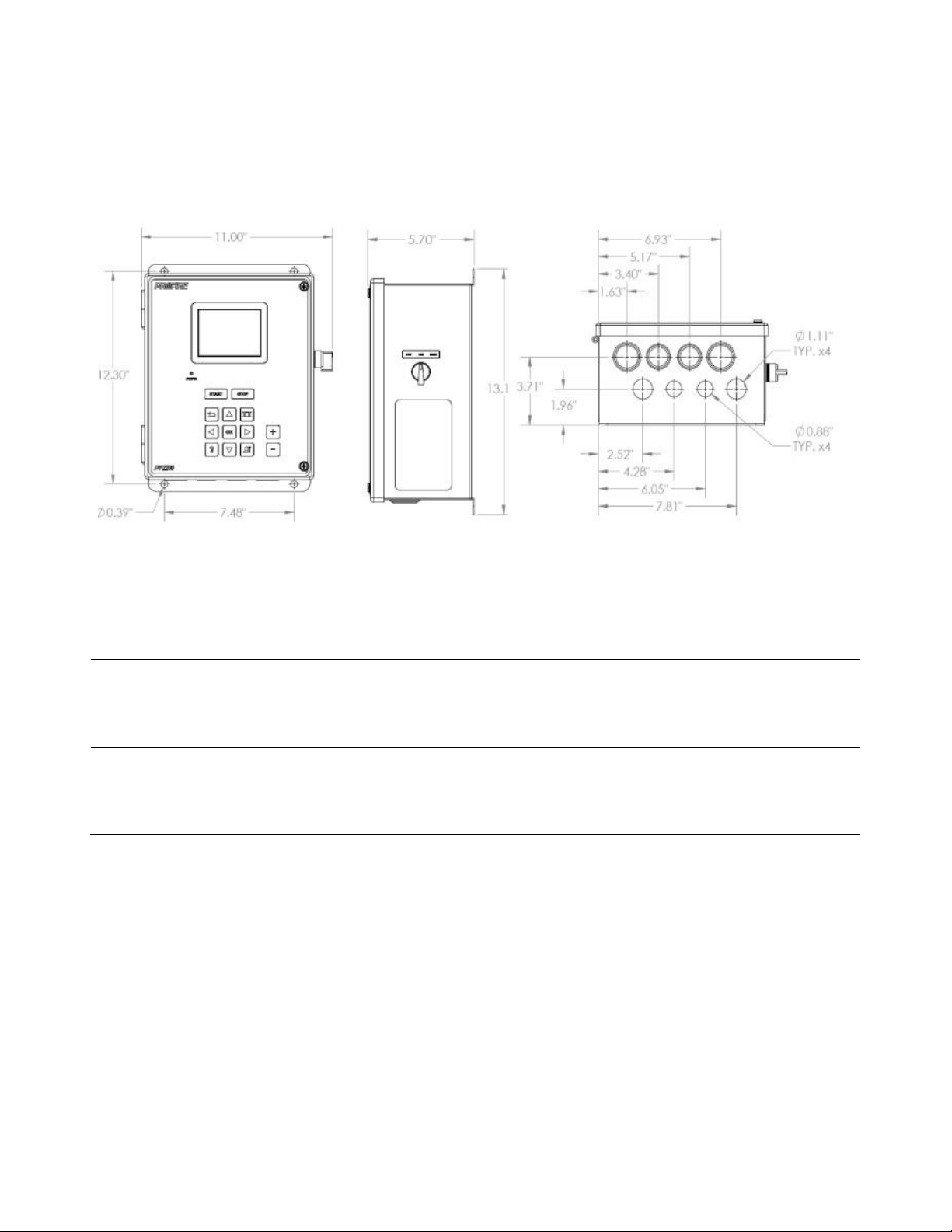
ENCLOSURE SPECIFICATIONS
PF2200-SB-A Stainless Steel Enclosure
Item Description
Enclosure Construction
3/6" Stainless Steel
Ingress Protection
IP66/NEMA 4
Operating Temperature Rating
-40 to 55°C / -40 to 131°F
Dimensions with Optional Manual Switch
13.17(h) X 11.00(w) X 5.70(d)
Dimensions without Optional Manual Switch
13.17(h) X 9.64(w) X 5.70(d)

DOC-001041 / v1.0
8
MOUNTING CONSIDERATIONS
The PF2200 has the approvals for installation in a Zone 2 or Class 1 Division 2 locations. The enclosure is
typically mounted near the burner it is controlling or in another location that is both safe and easily
accessible. The recommended mounting height is 1.5m (5ft) above the ground or a platform for the comfort
of the operators. Ensure that the BMS is mounted in a safe area for operation. Look for tripping, high heat
exposure, and other potential hazards.
ACCESSIBILITY
PF2200 enclosures shall be mounted upright in such a way that the screen is clearly visible, and the keypad is
easy to access. Adequate space should be provided so that the enclosure door can fully open during
maintenance and commissioning.
SECURITY
In some situations, it may be desirable to mount the system in a location not accessible to the general public
to prevent accidental or intentional tampering.
OPERATOR SAFETY
Avoid placing the system in locations that are dangerous to the operator. Examine the area surrounding the
potential installation site and look for such things as nearby open flames or close proximity to tanks that
might overflow, and other potentially harmful situations.
PERFORMANCE
Enclosures should be mounted to minimize the run-lengths to the burner assembly (ignition coil/rod and
flame detect rod), as well as the valve train (solenoids) and temperature inputs elements.

DOC-001041 / v1.0
9
PRODUCT PROTECTION
To protect the system from being damaged, it should not be mounted:
1. Where chemicals may splatter or bubble over from a tank onto the system. Chemicals on the keypad
may interfere with an operator’s ability to control the product or view the display and LED indicators.
2. Directly to a heated tank where excessive heat may damage the product. Refer to the maximum
operating temperature listed in this document.
3. Where anything may tip over due to wind or snow, some examples include poles that are not
appropriately secured into the ground or tripods not secured with anchor bolts or guy wires.
4. In locations that have a tendency of flooding.
IMPORTANT NOTE: It is recommended to avoid drilling into the top of the enclosure. If possible, side access
is better.
CONDUIT/CABLE/ENVIRONMENTAL CONSIDERATIONS
It is essential to ensure the cable and conduits to meet local code requirements to ensure the best
compliance, performance as well as a safe environment.
The PF2200 Single Burner BMS is designed, validated and verified under the following environmental
conditions.
System Voltage Range:
•12V mode: 10.2 –16.2 V
•24V mode: 20.4 –32.4 V
Ambient Temperature Range
•Operating: -40 to 55°C / -40°F to 131°F
•Storage: -40 to 55°C / -40°F to 131°F

DOC-001041 / v1.0
10
USER INTERFACE CARD ELECTRICAL RATINGS
The User Interface card is mounted on the back of the door panel of the enclosure.
Terminals
Electrical Rating
Wire Gauge / Torque
4 & 7 (Power Input +/-)
7 –35 VDC 500
mA Max
14-30 AWG
0.22-0.25 Nm
1-3
(Modbus A/B/-)
-7V to 17V Common Mode Range
9600 and 19200 bps (configurable)
8 Data Bits, No Parity, 1 Stop Bit
14-30 AWG
0.22-0.25 Nm
USB
5VDC
200 mA Max
N/A
Keypad
3VDC
4.75k Source Impedance
N/A
DOC-001041 / v1.0
11
BMS CARD
BMS Card Specifications
The ambient temperature rating for the BMS Card is -40°C (-40°F) to +55°C (+131°F).
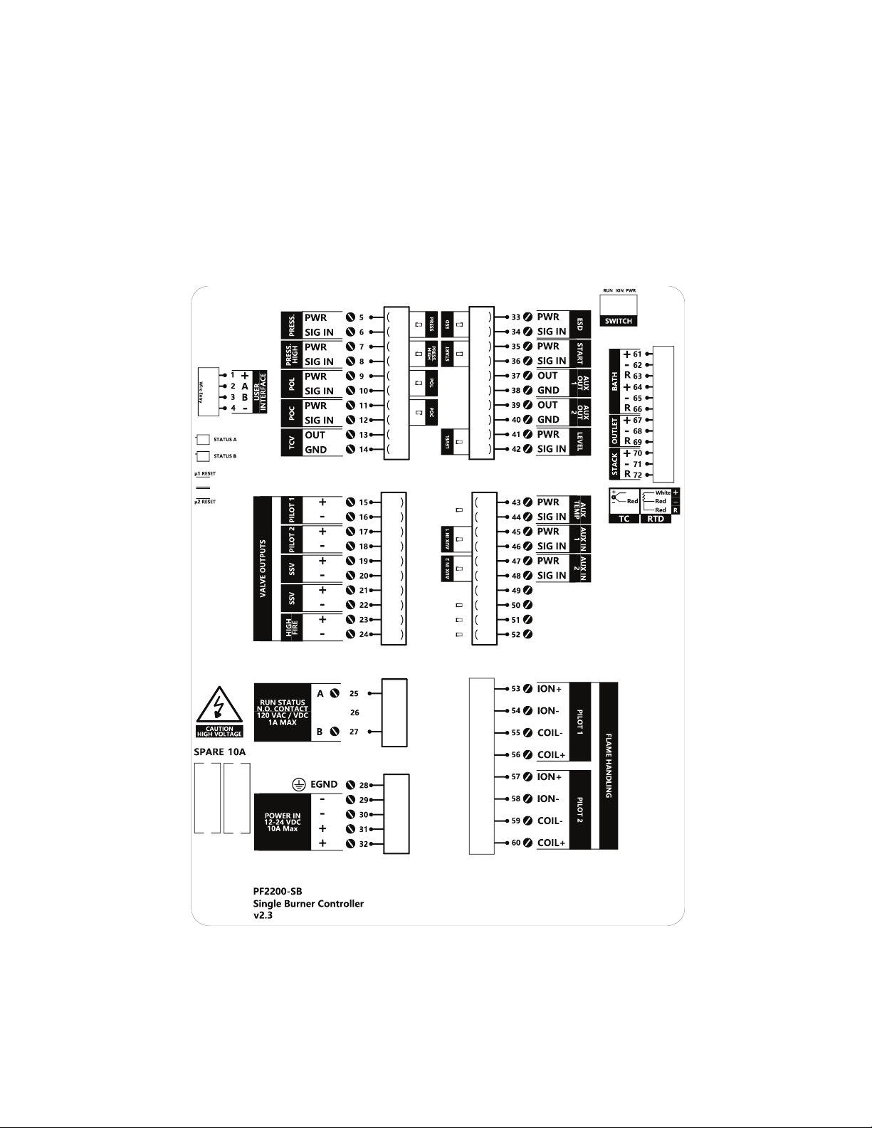
BMS Card Diagram

DOC-001041 / v1.0
12
BMS CARD ELECTRICAL RATINGS
I/O Type
Terminals
Electrical Rating
Wire Gauge
/ Torque
Powered Output
15-16 (Pilot 1) 19-20 (SSV)
17-18 (Pilot 2) 21-22 (SSV)
12 / 24VDC, 5A Max
Expected Load: Inductive /
Resistive
12-30 AWG
0.5-0.6 Nm
Powered Output
55-56 (Coil Pilot 1)
59-60 (Coil Pilot 2)
12 / 24VDC Pulsed Output [PWM]
Expected Load: Inductive
12-30 AWG
0.5-0.6 Nm
Ionization I/O
53-54 (Ion Pilot 1)
57-58 (Ion Pilot 2)
Intermittent 80-130 VRMS Output @
5kHz (with 20kΩ source resistance)
12-30 AWG
0.5-0.6 Nm
Start/Stop
Switch
Switch Internal (IGN, RUN,
PWR)
Power: 3.3V (1kΩ source
resistance)
Ignite / Run: 3.3VDC Max (~10kΩ
load)
12-30 AWG
0.5-0.6 Nm
Digital Input
7-8 (Press. High) 11-12
(PoC)
33-34 (ESD) 35-36 (Start)
Energized State: 10VDC, 1.25mA
Min
De-energized State: 3VDC, 500uA
Max
30 VDC Max
12-30 AWG
0.5-0.6 Nm

DOC-001041 / v1.0
13
Digital /
4-20mA Input
5-6 (Press.)
9-10 (POL)
41-42 (Level)
43-44 (Aux. Temp)
45-46 (Aux. In 1)
47-48 (Aux. In 2)
Power Out:
12V Mode = 12VDC, 24V Mode =
13.5 VDC
30mA Max
Digital Input (if applicable):
Energized State: 10VDC, 1.25mA
Min
De-energized State: 3VDC, 500uA
Max
30 VDC Max
4-20mA Input:
+/- 0.1 mA accuracy
50mA current limit 30
VDC Max
12-30 AWG
0.5-0.6 Nm
Temperature Input
61-66 (Bath)
67-69 (Outlet)
70-72 (Stack)
RTD (PT-100):
-100 to 850C [60.25Ω to 390.5Ω]
+/- 0.5°C accuracy
Temperature inputs (Type-K):
14-30 AWG
0.22-0.25
Nm
I/O Type
Terminals
Electrical Rating
Wire Gauge
/ Torque
-100 to 1350°C [-3.554mV to
54.1mV]
+/- 2°C accuracy
Ground-biased
4-20mA Output
13-14 (TCV)
37-38 (Aux. Out 1)
39-40 (Aux. Out 2)
20 mA Max
Expected Load: Resistive (< 350Ω)
+/- 0.1mA accuracy
12-30 AWG
0.5-0.6 Nm
Relay Output
25-27 (Status)
120 VAC, 170V Peak Max
1ARMS Max
12-30 AWG
0.5-0.6 Nm
* The Bath Temperature Input is safety rated ONLY if the input is configured as a Dual. If configured as a
Single element, the Bath temperature input is NOT safety rated.

DOC-001041 / v1.0
14
WIRING
The wiring in this section is required for all PF2200 installations. Skipping or performing any steps in this
section incorrectly will result in the PF2200 functioning improperly. Conduct pull tests on terminating wires in
the BMS to ensure proper installation. Install tags identifying that electrical seals have not been poured on
electrical connectors entering the PROFIRE BMS.
POWER
The PF2200 can be powered from 12V or 24V. The maximum current that the PF2200 can safely handle
without blowing the main fuse is 10A. The system on its own draws about 100mA. The rest of the current is
used by additional hardware such as valves. Make sure that you select a power supply that is rated
appropriately for the total amount of current that is consumed by the system, and all devices attached to it.
For more information on the wiring guidelines see WIRING in the Product Manual.
PILOT VALVE OUTPUTS (Pilot 1 & Pilot 2)
Two powered outputs (terminals 15-16 and 17-18) are intended to be connected to solenoid valves which
control the fuel line for the pilots. When Pilot 2 is enabled, both outputs work in conjunction with one
another. Meaning that they open and close in unison. If Pilot 2 is disabled, the Pilot 2 output stays
deenergized. The Pilot Outputs are capable of peak and hold PWM output mode at a fixed 3 kHz frequency.
Supported duty cycles for PWM mode are 10-100% and are configurable via the user interface. Depending on
the selected input type, the Pilot valve has a maximum of 5 amps and 12 / 24 volts.
MAIN VALVE OUTPUTS (SSV)
Two powered outputs (terminals 19 and 20) are intended to be connected to solenoid valves which control
the fuel line for the main burner. Both outputs work in conjunction with one another. Meaning that they open
and close in unison. The Main Valve Outputs are capable of peak and hold PWM output mode at a fixed 3
kHz frequency. Supported duty cycles for PWM mode are 10-100% and are configurable via the user
interface.
DOC-001041 / v1.0
15
TEMPERATURE INPUTS
There are four distinct temperature inputs available: Bath, Outlet, Stack, and Aux. The Bath, Outlet, and Stack
inputs are configurable to accept either a Type-K thermocouple or a PT-100 RTD sensor. The Aux temperature
input on terminals 43-44 is intended to be connected to a temperature sensor with a 4-20mA interface.
The Bath input is mandatory and must be connected to a Dual Element temperature sensor. The Outlet, Stack,
and Auxiliary temperature inputs are optional and can be utilized to monitor secondary process temperatures
such as the outlet temperature on a line heater. Unused temperature input terminals can be left unconnected.
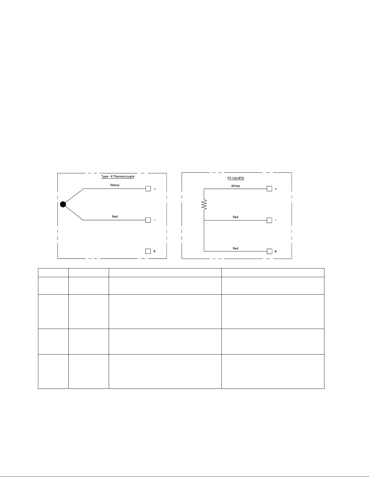
When wiring thermocouples, Type-K thermocouple extension wire must be utilized to avoid cold junctions,
leading to inaccurate readings.
Below are the wiring diagrams for the Type –K Thermocouple and the RTD Temperature inputs.
Input
Terminals
Type
Modes Supported
Bath
61-66
PT-100 RTD or Type-K Thermocouple
Dual Element or Single Element
High Temp ESD
Process Control
Outlet
67-69
PT-100 RTD or Type-K Thermocouple
Single Element
Disabled
High Temp ESD
Process Control
Display Only
Stack
70-72
PT-100 RTD or Type-K Thermocouple
Single Element
Disabled
High Temp ESD
Display Only
Aux
43-44
4-20mA Transmitter
Disabled
High Temp ESD
Process Control
Display Only

DOC-001041 / v1.0
16
COIL
The PF2200 system must be connected to a PROFIRE ignition coil.
SINGLE ROD CONFIGURATION
FLAME DETECTION WIRE LENGTH LIMITATIONS
Distance Between 2200 and Pilot *
Wire Size
0 - 10 feet
14 - 16 gauge
10 - 25 feet
7mm Ignition Wire
25 - 60 feet
7mm Ignition Wire
*For single rod installations, the distance is defined as the length from the positive ion terminal, to the
ignition coil, plus the distance from the ignition coil, to the ignition/flame rod as shown in the Single Rod
Wiring Diagram. Note that the ignition wire should be no longer than 3m (10 ft).
DOC-001041 / v1.0
17
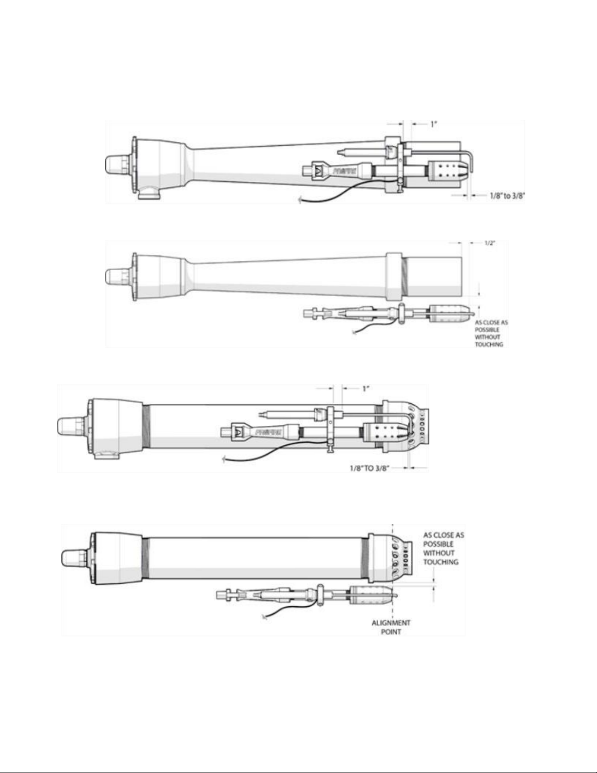
INSTALLATION DIAGRAMS
Figure 1: Burner with Ferrofix nozzle –side view.
Figure 2: Burner with Ferrofix nozzle –top view.
Figure 3: Burner with bell nozzle - isometric.
Figure 4: Burner with bell nozzle –top view.

DOC-001041 / v1.0
18
Figure 5: Burner with Ferrofix nozzle and Inline Igniter –Side View.
Figure 6: Burner with Ferrofix nozzle and inline Igniter –Top View.
Figure 7: Burner with Bell nozzle and Inline Igniter –Side View.
Figure 8: Burner with Bell nozzle and Inline Igniter –Top View.

DOC-001041 / v1.0
19
PRE / POST-ASSEMBLY CHECKLIST
The following checklist will help ensure proper installation techniques for the PF2200 Burner Management
System, fuel train components, and burner components. This checklist should be consulted before and after
installation, to ensure requirements are met for the installation of the system.
1. Ensure that the BMS is mounted in a safe area for operation. Look for tripping, high heat exposure,
and other potential hazards.
2. Conduct pull tests on terminating wires in the BMS to ensure proper installation.
3. Install tags identifying that electrical seals have not been poured on electrical connectors entering the
PROFIRE BMS.
4. Ensure the Type K temperature inputs wire is used. (Yellow = positive and red = negative).
5. Point to point wiring is a must with temperature inputs wires (no cold junctions). A cold junction can
cause inaccurate temperature readings and therefore, poor temperature performance.
6. Do not hook up shield wires; this should be done in the field if necessary. It is common to terminate
the shield wires to earth ground or ground grid of each vessel skid; however, this can only be done
upon field installation. The temperature inputs are shipped loose and installed on location in the
vessel. The wiring is completed at that time.
7. For flame detection to work correctly, the flame must be in physical contact with both the flame
detection rod and the grounded pilot nozzle. This allows a current path from the flame detection rod
through the flame to ground. When nozzle velocity is high, the flame may not make contact with the
nozzle. This situation is referred to as "poor flame anchoring." To resolve poor flame anchoring, add a
second grounded Kanthal rod can be placed further in front of the nozzle so that it catches the flame.
DOC-001041 / v1.0
20
COMMISSIONING
TIME AND DATE SETTING
When commissioning, set the time and date the current time and date in your region. Once set, the time stays
consistent even in the event of a significant power interruption. In the case of an extended power down of the
BMS, the time should be checked and set if necessary to maintain accurate logging of the systems events.
Follow the steps below to set the Date and Time on the PF2200.
•Enter Commissioning mode - Press the Commission key and acknowledging the prompt with the
OK key to complete the entry to Commissioning mode.
•Navigate to Settings Screen - Use the Carousel key to navigate to the Setting screen.
•Enter Commissioning screen - Use the Arrow keys to highlight Commissioning under the Setup
sub menu, and press the OK key.
•Enter Date and Time setting Screen - Use the Arrow keys to highlight the Date and Time and
press the OK key.
•Adjust Date and Time - Use the Arrow keys to highlight the Date and Time elements and adjust the
date and time elements using the Plus and Minus keys.
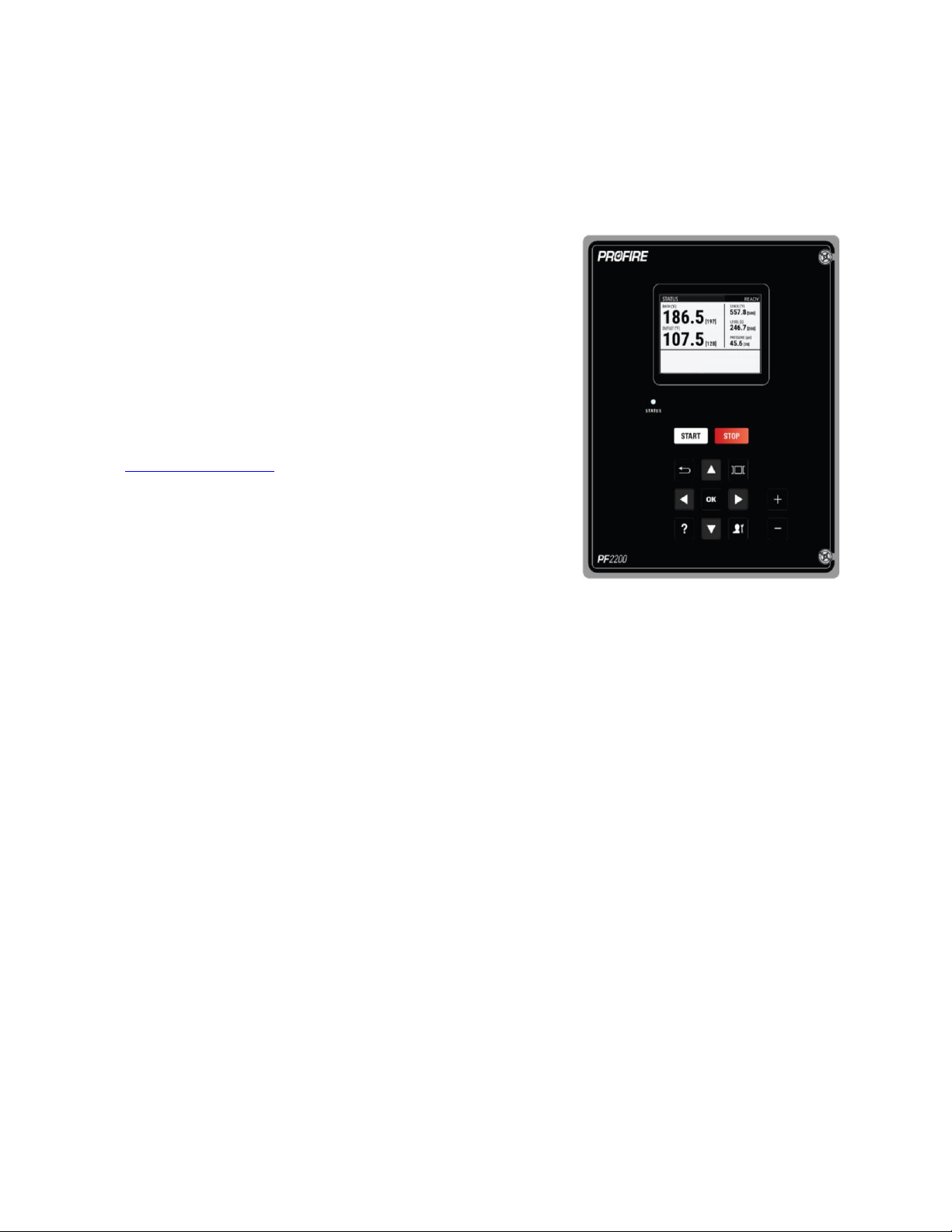
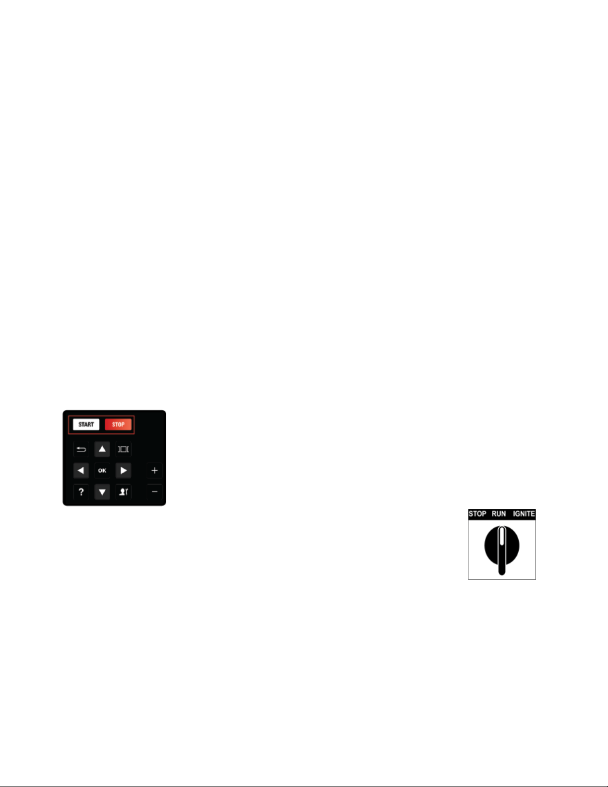
STARTING/STOPPING
Starting and Stopping the PF2200 is done by pressing the Start or Stop key on the
keypad. The system then prompts the user to acknowledge the action. Acknowledging
can be done by pressing the Start or Stop key again or pressing the OK key.
Optionally starting and stopping the PF2200 can be done with the optional manual
Start/Stop switch.
There are three functional positions, as shown. When in the Stop
position, all safety outputs are de-energized. Toggling from the Run position to the
Ignite position for more than 2 seconds initiates the ignition sequence. Toggling the
switch from the Stop position to the Run position can clear a lockout state.
The optional Manual Switch, part number PFA-004260, mentioned above can be ordered by contacting Profire
Energy (reference the back cover of this manual for all Profire contact information).
NOTE: Holding the switch in the Ignite position for more than 4.5 seconds results in a system shutdown on an
External Stuck Switch event.
Other manuals for PF2200-SB
4
This manual suits for next models
1
Other ProFire Control Panel manuals


