Schaudt LT 500 User manual

© 2005 Schaudt GmbH, Elektrotechnik & Apparatebau, Daimlerstraße 5, 88677 Markdorf, Germany, Phone +49 7544 9577-0, Telefax +49 7544 9577-29, www.schaudt-gmbh.de
SDT-0060-00EN Situation: 17.06.2005 831.300
0 Instruction Manual Control and Switch Pan el LT 500
Instruction manual
Control and switch panel LT 500
Table of contents
1 Introduction . . . . . . . . . . . . . . . . . . . . . . . . . . . . . . . . . . . . . . . . . .2
2 Safety information . . . . . . . . . . . . . . . . . . . . . . . . . . . . . . . . . . . . .2
3 Description and appropriate use . . . . . . . . . . . . . . . . . . . . . . . . . .3
4 Electrical data. . . . . . . . . . . . . . . . . . . . . . . . . . . . . . . . . . . . . . . . .4
5 Operation . . . . . . . . . . . . . . . . . . . . . . . . . . . . . . . . . . . . . . . . . . . .4
6 Starting up . . . . . . . . . . . . . . . . . . . . . . . . . . . . . . . . . . . . . . . . . .11
7 Maintenance. . . . . . . . . . . . . . . . . . . . . . . . . . . . . . . . . . . . . . . . .11
8 Shutting down . . . . . . . . . . . . . . . . . . . . . . . . . . . . . . . . . . . . . . .12
9 Technical faults, possible causes and remedies . . . . . . . . . . . . .13
10 Customer service. . . . . . . . . . . . . . . . . . . . . . . . . . . . . . . . . . . . .13
11 Circuit diagram - for specialist workshop only . . . . . . . . . . . . . . .14
12 Fault report. . . . . . . . . . . . . . . . . . . . . . . . . . . . . . . . . . . . . . . . . .15

2Situation: 17.06.2005 831.300 SDT-0060-00EN
Instruction Manual Control and Switch Panel LT 500
1 Introduction
This instruction manual contains important information for the safe operation
of the control and switch panel. It is essential to read and to follow the given
safety information.
The instruction manual should always be kept in the motorhome/caravan. All
safety information must be passed on to other users.
The reproduction, translation and duplication of this manual, even in parts, is
not allowed without written authorization.
2 Safety information
The design of the control and switch panel is state-of-the-art and according to
approved safety technology regulations. Nevertheless, if the safety informa-
tion in this instruction manual is not closely followed, persons might be injured
or the control and switch panel might be damaged.
Do not use the control and switch panel if it is not in technically good order
and condition. The instruction manual must be followed.
Any technical faults affecting the safety of persons or of the control and switch
panel must be dealt with immediately by qualified personnel.
W
Failure to comply with this sign may lead to the endangerment of per-
sons.
W
Failure to comply with this sign may damage the device or the connected
consumers.
W
This sign indicates recommendations or special features.
W
The electrical system of the motorhome or the caravan must meet cur-
rent DIN, VDE and ISO regulations. Manipulations of the electrical
system will endanger the safety of persons and the vehicle, and are
therefore prohibited.
W
Never make any modifications to the control and switch panel.
W
Connection work is to be carried out in tensionless condition only.
W
The electrical connection may only be established by qualified person-
nel and must be carried out according to the Schaudt installation
instructions.
W
If the living area battery is totally discharged or overcharged for a lengthy
period, it will be irreparably damaged.
W
Switch off the 12 V main switch when you leave the vehicle. This prevents
the living area battery from unnecessarily discharging.

SDT-0060-00EN Situation: 17.06.2005 831.300 3
Instruction Manual Control and Switch Panel LT 500
3 Description and appropriate use
The job of the control and switch panel IT 500 is to control the electrical func-
tions in the living area of the motorhome and display various values such as
voltages and battery currents or water tank levels.
This system includes:
P
An Electrobloc, consisting of a charger module, the 12 V distribution and
the fuses for each circuit
P
Tank sensors for measuring the level in the water tanks
Fig. 1 Control and switch panel LT 500
1 12 V indicator lamp, green
2 12 V main switch/pump switch
3 Indicator lamp for pump power supply, yellow
4 Indicator LEDs: tank level, charging and discharge current, battery voltage
5 Percentage scale display: battery capacity/tank level "%"
6 230 V indicator lamp, yellow
7 Indicator lamp for waste water tank heater, yellow
8 Switch for tank level/waste water tank heater
9 "Unclear value" warning lamp, red "?"
10 Battery switch
11 Charge request "CHARGE !" warning lamp, red
12 Charging and discharge current scale "A"
13 Battery voltage scale "V"
14 Scale points
The 3 switches on the control and switch panel can be used for calling up var-
ious information and functions.
After letting go of the corresponding switch, the indicated values are still dis-
played for approx. 10 seconds.
SDT00277
1 2 3 4 75 6
891011121314

4Situation: 17.06.2005 831.300 SDT-0060-00EN
Instruction Manual Control and Switch Panel LT 500
Values indicated on the
display The indicated values are displayed in an illuminated band with 32 yellow indi-
cator LEDs in 16 levels. 5 scale points above and 5 below the illuminated
band indicate the range and make it easier to read the display. The right end
of the display shows the scale with illuminated units in percent (%), volts (V)
and amperes (A).
The brightness of the scale points and indicator LEDs is controlled depending
on the ambient light. The darker the ambient light, the darker the scale points
and indicator LEDs.
The following table shows possible indicated values.
The control and switch panel has bold-type numerical values.
4 Electrical data
5 Operation
5.1 Switching the 12 V power supply for the living area
on and off
12 V main switch/pump
switch The 12 V main switch/pump switch turns all consumers on and off.
Exceptions:
P
Frost protection valve
P
Heater
P
Step
P
Gas alarm/waste water valve
P
Circuits 4 and 5
P
Waste water tank heater
P
Pull-down bed
P
Awning light
P
Awning
P
Satellite antenna
P
Compressor or AES refrigerator
Press the left side of the switch briefly:
The 12 V power supply is switched on. The green 12 V indicator lamp
lights up.
Press the left side of the switch again briefly:
The 12 V power supply is switched off. The green 12 V indicator lamp does
not light up.
Indicator
LEDs 0 2 4 6 8 101214161820222426283032
Capacity % 0613 19 25 31 38 44 50 56 63 69 75 81 88 94 100
Current A 0 0.1 0.15 0.2 0.3 0.45 0.7 11.5 234.5 710 15 20 30
Voltage V 10.7 11.0 11.2 11.5 11.7 12.0 12.2 12.5 12.7 13.0 13.2 13.5 13.7 14.0 14.2 14.5 14.7
Operating voltage 12 V (10–14.5 V), powered via Electrobloc

SDT-0060-00EN Situation: 17.06.2005 831.300 5
Instruction Manual Control and Switch Panel LT 500
The control and switch panel can only be switched on if the living area battery
voltage is above 11.0 V. If the living area battery voltage is insufficient, the
12 V indicator lamp and the "V" symbol flash.
5.2 Switching the power supply for the pump on and off
12 V main switch/
pump switch
Press the right side of the switch briefly:
The pump can be switched on. The yellow indicator lamp lights up.
Press the right side of the switch again briefly:
The pump cannot be switched on. The yellow indicator lamp does not light
up.
5.3 230 V mains indicator
230 V indicator lamp The yellow 230 V indicator lamp lights if the input of the Electrobloc is live.
The yellow 230 V indicator lamp flashes if the vehicle's engine is started and
if at the same time the input of the Electrobloc is live.
5.4 Checking the battery capacity and charging current
of the living area battery
Battery switch Press the left side of the battery switch once briefly:
The battery capacity is indicated on the "%" scale in 16 levels from 0 to
100 %. The illuminated scale points indicate the critical zone in red, the
normal range is green.
Press the left side of the battery switch twice briefly:
The charging/discharge current is indicated on the "A" scale in 16 levels
from 0 to 30 A.
The scale points light up in green: The charging current is displayed or 0 A.
The scale points light up in red: The discharge current is displayed.
The display shows all types of battery voltage:
P
Via the charger module of the 230 V mains
P
Via the cut-off relay of the alternator while driving
P
Via a solar charge regulator connected to the system
W
Switch off the 12 V main switch when you leave the vehicle. This pre-
vents the living area battery from unnecessarily discharging.
W
When the pump's power supply is switched off, the water tap can be
opened without the pump starting (for example for draining the water
pipes).

6Situation: 17.06.2005 831.300 SDT-0060-00EN
Instruction Manual Control and Switch Panel LT 500
5.5 Checking the battery voltage
Battery voltages are indicated on the "V" scale in 16 levels from 10.7 V
to 14.7 V. The illuminated scale points indicate the critical zone in red, the
normal range is green.
Battery switch Press the left side of the battery switch three times briefly:
The living area battery voltage is indicated in volts on the "V" scale.
Press the right side of the battery switch once briefly:
The starter battery voltage is indicated in volts on the "V" scale.
In mobile operation, the voltage of the starter battery is indicated slightly too
low if the refrigerator is on with 12 V. If the refrigerator is switched off or oper-
ated using gas, the indicated voltage is correct. If the engine is switched off,
the voltage of the starter battery is also indicated correctly.
The following table will help you correctly interpret the living area battery volt-
ages displayed by the control and switch panel. These values only apply to
lead gel batteries in use, not to off-load voltage.
1) depending on the current load
Battery voltage Description
Less than 10.5 V
P
Risk of total discharge
P
The battery monitor switches off all
consumers (apart from the frost
protection valve)
11 V or more The 12 V power supplycan be switched
on using the main switch
10.5 V to 12 V
P
If the voltage falls below 12 V, the
battery alarm is triggered
P
Warning lamp "CHARGE !" flashes
P
If the voltage remains under
11-12 V 1) for more than 1 minute, the
battery capacity is set to "zero"
P
If the voltage remains under
11-12 V 1) for more than 5 minutes,
the system is switched off
12 V to 13.2 V Battery off load
More than 13.2 V Battery is being charged: Main charge
13.8 V constant Trickle charge voltage
14.3 V Final charging voltage (equalising
charge)
P
1 h for lead acid battery
P
8 h for lead gel battery
W
If the living area battery is totally discharged or overcharged for a lengthy
period, it will be irreparably damaged.
W
If the 12 V power supply is overloaded, switch off some of the consumers.
W
Inactive consumers can gradually discharge the battery.

SDT-0060-00EN Situation: 17.06.2005 831.300 7
Instruction Manual Control and Switch Panel LT 500
Checking the condition of
the battery Measuring the off-load voltage is a simple and effective method of checking
the condition of the battery. Off-load voltage is the voltage of the charged bat-
tery in a passive state, with no current being supplied or drawn.
Take themeasurementseveralhours afterthelast charging. Inthe meantime,
no significant load should have been placed on the battery, which means no
current should have been drawn from it. If the off-load voltage of the battery
is less than 12.0 V, there is a risk of total discharge.
The following table will help you interpret the off-load voltage displayed.
These values apply for lead gel batteries.
It is advisable to check the off-load voltage in the morning before consumers
are switched on.
Charge request
"CHARGE !" The batteries should be fully charged every 4 weeks to achieve a long service
life.
As a reminder a charge request is displayed as a red "CHARGE !" warning
light 20 days after the last equalising charge or if the capacity of a battery has
fallen below 15 %.
Connect the motorhome to the 230 V power supply.
The batteries are charged..
5.6 Indication of the maximum possible battery capacity
The maximum battery capacity of the living area battery can be indicated, but
it cannot be set. The maximum battery capacity is displayed in % of the nom-
inalcapacity.Thepresetvalue of80 %(26 indicator LEDslight up) represents
the maximum battery capacity that can be used practically. The value can rise
to more than 80 %.
Battery switch Press the right side of the battery switch for more than 5 seconds:
The maximum battery capacity is indicated on the "%" scale in 16 levels
from 0 to 100 %. The illuminated scale points indicate the critical zone in
red, the normal range is green. The "%" display flashes.
The control and switch panel recalculates the maximum battery capacity after
every complete charging cycle (total charge and total discharge) and indi-
cates the current value. This display applies only to the living area battery.
Values for off-load voltage Charging condition of the battery
Less than 10.5 V Totally discharged
12.0 V 0 %
12.2 V 25 %
12.3 V 50 %
12.5 V 75 %
More than 12.8 V Full
W
For more information see section 5.12 as well as the instruction manual of
the Electrobloc.

8Situation: 17.06.2005 831.300 SDT-0060-00EN
Instruction Manual Control and Switch Panel LT 500
The maximum battery capacity no longer reaches the preset value once the
battery starts to get old. The reduction of the maximum battery capacity gives
information on the condition of the living area battery. If only 50 % of the nom-
inal capacity is indicated, check the living area battery and replace it if neces-
sary.
A brand new battery reaches its full capacity only after several charge cycles.
5.7 Indication of the software version number
Battery switch Press the right side of the battery switch for more than 5 seconds:
The maximum battery capacity is indicated. The "%" symbol flashes.
Press the right side of the battery switch again briefly:
The software version number is indicated.
The software version number is a number between 0 and 8, displayed in 8 lev-
els with 2 illuminated indicator LEDs for each stage. For example, 2 indicator
LEDs light up for software version 1.00, 8 light up for software version 4.00.
5.8 Displaying and setting the nominal battery capacity
of the living area battery
The nominal capacity is set to 90 Ah at the factory. The nominal capacity can
be set (e.g. in the event of retrofitting a battery) within the range of 60 Ah to
220 Ah.
Display principle The number of illuminated indicator LEDs indicates the set nominal capacity.
60 Ah: No indicator LED lights up
220 Ah: All indicator LEDs light up
In addition to the minimum capacity of 60 Ah, 2 indicator LEDs light up for eve-
ry additional 10 Ah.
Example: If 12 indicator LEDs light up, that means:
60 Ah + 6 x 10 Ah = 120 Ah battery capacity
Displaying and setting the
nominal capacity
Press the left side of the battery switch and the right side of the tank level
switch for more than 5 seconds.
When the "%" symbol flashes, let go of both switches.
The illuminated indicator LEDs indicate the set nominal capacity for the liv-
ing area battery.
If the nominal capacity is not to be changed:
Press the battery switch. The display goes out after 20 seconds.
If the nominal capacity is to be changed:
Press the right side of the tank level switch:
The nominal capacity is increased by 10 Ah.
Press the left side of the tank level switch:
The nominal capacity is reduced by 10 Ah.
Press the left side of the 12 V main switch:
The new value is saved and the setting is completed.
20 seconds after pressing the button for the last time, the control and switch
panels switchers back to its basic condition. If the newly set nominal capacity
has not been confirmed using the 12 V main switch by then, it is not saved.

SDT-0060-00EN Situation: 17.06.2005 831.300 9
Instruction Manual Control and Switch Panel LT 500
5.9 Battery monitor
Automatic disconnector The battery monitor compares the living area battery voltage to a reference
voltage. Monitoring is continued, even when the control and switch panel is
switched off.
Alarm message and system shut down are dynamic processes, i.e. depend-
ing on the current drain, the alarm message is displayed or the system is shut
down sooner or later. This improves protection against total discharge of the
battery.
As soon as the battery voltage falls below 11.7 V, an alarm message is dis-
played (see the section 5.12 Additional messages).
As soon as the battery voltage falls below 10.5 V, all 12 V consumers are
switched off. Only the frost protection valve is still powered. The control and
switch panel also shuts down. Before shutting down, all switching conditions
and the battery capacity value are saved. The automatic disconnector is not
triggered by short-term low voltage, caused by high current when switching
on consumers.
If an overload or an insufficiently charged living area battery causes the volt-
age to fall so low that the automatic disconnector is triggered, it is essential to
switch off all consumers that are not required.
You may be able to switch the 12 V power supply back on for a short time.
Press the left side of the 12 V main switch.
The 12 V power supply is switched on.
If the battery voltage remains below 11.0 V, you cannot switch the 12 V power
supply back on. If an attempt is made to switch it on, the 12 V indicator lamp
and the "V" symbol flash.
Fully charge up the living area battery as soon as possible.
5.10 Checking the tank level
Observe the "%" display on the scale. The tank level is displayed in 4 stages
0 % to 25 %, 50 %, 75 % and 100 % by the indicator LEDs. The illuminated
scale points indicate the critical zone in red, the normal range is green.
Tank level switch Press the left side of the tank level switch briefly:
The water tank level is displayed.
Press the right side of the tank level switch briefly:
The waste water tank level is displayed.
5 seconds after pressing the switch for the last time, the display is switched
back off again.
W
To set the nominal capacity of the living area battery, always enter the
K100 value stated onthe battery.If no K100 valueis specified, readoff the
K20 value and multiply it by 1.125.
W
The tank levels must not be checked permanently. The sensors might get
damaged if used permanently.

10 Situation: 17.06.2005 831.300 SDT-0060-00EN
Instruction Manual Control and Switch Panel LT 500
5.11 Switching the waste water tank heater on and off
The waste water tank heater still works when the control and switch panel is
switched off. To switch the waste water tank heater on and off, the control and
switch panel must be switched on.
Tank level switch Press the right side of the tank level switch for more than 3 seconds:
The waste water tank heater is switched on. The yellow indicator lamp
lights up.
Press the right side of the tank level switch again for more than 3 seconds:
The waste water tank heater is switched off. The yellow indicator lamp
does not light up.
5.12 Additional messages
5.12.1 Charge request "CHARGE !"
The red "CHARGE !" warning lamp flashes as soon as the battery voltage is
insufficient. The system shuts down after approx. 5 minutes. This alarm mes-
sage still appears, even if the control and switch panel is switched off. The
batteries must now be recharged.
For more information see section 5.5 as well as the instruction manual of the
Electrobloc.
The control and switch panel can only be switched on, if the living area battery
voltage is above 11.0 V. If the voltage is insufficient, the 12 V indicator lamp
and the "V" symbol flash if an attempt is made to switch on the control and
switch panel.
5.12.2 Battery capacity alarm
If the residual capacity of the living area battery voltage is insufficient (below
approx. 15%), the red "CHARGE !" warning lamp lights up. Charge the bat-
teries. The battery capacity alarm is not active when the 12 V main switch is
switched off.
5.12.3 Battery capacity unclear
If the battery capacity is checked and the system is not able to determine a
clear value, the red "CHARGE !" warning lamp and the red "?" warning lamp
flash. This can for example happen after starting up the system or after
changing batteries.
Fully charge the battery using the 230 V power supply, a defined charge sta-
tus is then restored. When the charging process is completed, both warning
lamps go out.
5.12.4 Mains alarm
The yellow 230 V indicator lamp flashes when the vehicle's engine is started
and if at the same time the input of the Electrobloc is live.

SDT-0060-00EN Situation: 17.06.2005 831.300 11
Instruction Manual Control and Switch Panel LT 500
5.12.5 Tank check unclear
If the tank level is checked in stationary operation, the red "?" warning lamp
flashes if there is a malfunction of the tank sensors. Check the sensors and
clean them if necessary.
If the tank level is checked in mobile operation, the red "?" warning lamp flash-
es. The tank level cannot be displayed accurately while driving because the
water in the tank will slosh around.
6 Starting up
The control and switch panel can only be started up with an Electrobloc and
the accessories for measuring the water tank levels.
After shutting down If the battery is separated from the system (battery separation by the control
and switch panel or a battery pole is disconnected): Check the off-load volt-
age of the battery immediately after start up. Do not connect the vehicle to the
230 V mains, do not start the engine and do not switch on any consumers
until the off-load voltage of the battery has been checked.
After an off-load time of maximum 6 months, the battery voltage should be
above 12.7 V if the battery was fully charged before shut down. If the voltage
is below 12.0 V, then the battery might be defective and need to be replaced.
Starting up the system Press the 12 V main switch for more than 5 seconds. The 12 V indicator
lamp flashes. The system has been activated. For information on other
measures after starting up the system, see the instruction manual for the
Electrobloc.
7 Maintenance
The control and switch panel requires no maintenance.
Cleaning Clean the front plate with a soft, slightly damp cloth and a mild detergent.
Never use spirit, thinners or similar substances.
Do not allow any fluid to penetrate the inside of the control and switch panel.
W
Connection work is to be carried out in tensionless condition only.

12 Situation: 17.06.2005 831.300 SDT-0060-00EN
Instruction Manual Control and Switch Panel LT 500
8 Shutting down
Switch off the system if you are not going to use the motorhome for a lengthy
period (for example during the winter). The separation of the batteries is
established using the control and switch panel. In doing so, the living area bat-
tery is switched off electrically. There is still a closed circuit current of
approx. 4.5 mA. The shut down system requires approx. 4 Ah a month.
Shutting down the system
for up to 6 months Fully charge up the living area battery before shutting down the system. The
living area battery is then protected against total discharge. This applies only
if the battery is intact. Follow the instructions of the battery manufacturer.
Switching off the system 1. Switch off the 12 V main switch on the control and switch panel.
2. Press the left side of the battery switch (living area battery) for more than
10 seconds. The entire scale display flashes twice briefly for confirmation.
Shutting down the system
for more than 6 months Fully charge up the living area battery and remove the clamps on the battery
poles. Carry out the following work steps in the sequence mentioned below.
The battery alarm is then no longer active.
Disconnecting the living
area battery from the 12 V
power supply
Carry out the following work steps in the correct sequence:
1. Switch off the 12 V main switch on the control and switch panel.
2. Press the left side of the battery switch (living area battery) for more than
10 seconds. The entire scale display flashes twice briefly for confirmation.
3. Remove the clamps from the battery poles.
W
For other shutdown tasks, see the instruction manual for the Electrobloc.

SDT-0060-00EN Situation: 17.06.2005 831.300 13
Instruction Manual Control and Switch Panel LT 500
9 Technical faults, possible causes and remedies
If you are unable to solve a fault using the following tables, please contact our
customer service address.
If this is not possible, e.g. if you are abroad, you can have the control and
switch panel repaired at a specialist workshop.
Inexpert repairs invalidate the guarantee for the control and switch panel and
Schaudt GmbH takes no liability for any resulting damage.
10 Customer service
Customer service address Schaudt GmbH, Elektrotechnik & Apparatebau
Daimlerstraße 5
88677 Markdorf
Germany
Phone: +49 7544 9577-16
Email: kundendienst@schaudt-gmbh.de
Sending in the device Returning a defective device:
Use ESD protective bag and well-padded packaging.
If there is no ESD protective bag, ask Schaudt GmbH for a suitable pro-
tective bag.
Fill in and enclose the fault report, see section 12.
Send it to the addressee delivered free.
Disposal instruction Whentheproductservicelifeisover,disposeofthe devicein accordancewith
the applicable regulations.
Fault Possible cause Remedy
12 V power supply does
not work 12 V main switch turned off Switch on the 12 V main
switch
System shut down Start up the system
No voltage in living area
battery Living area battery is dis-
charged Charge the living area bat-
tery immediately
W
If the living area
battery is totally
discharged for a
lengthy period, it
will be irrepara-
bly damaged
The battery can be dis-
charged by inactive appli-
ances such as the frost
protection valve in the
heater system
Fullychargethelivingarea
battery before you shut
down the motorhome for
any lengthy period
On checking the tank level
the "?" warning lamp flash-
es
Defective tank level sen-
sors Clean sensors or have
them checked
Opening hours Mon to Thu
Fri 8 to 12 a.m., 1 to 4 p.m.
8 to 12 a.m.

14 Situation: 17.06.2005 831.300 SDT-0060-00EN
Instruction Manual Control and Switch Panel LT 500
11 Circuit diagram - for specialist workshop only
Fig. 2 Circuit diagram for control and switch panel LT 500
615 1
12 1
110
X1
SDT00282
X2 X3 X4
Plug assignment for the
circuit diagram X1 block 3 Lumberg 2.5 MSFQ/0
6 x to water tank X2 block 4 Lumberg 2.5 MSFQ/0
5 x to waste water tank
1. Full 1. Full
2. 3/4 2. 3/4
3. 1/2 3. 1/2
4. 1/4 4. 1/4
5. Base water tank 5. Base waste water tank
6. Not assigned
X3 block 1 Lumberg 2.5 MSFQ/0
10 x X4 block 2 Lumberg 2.5 MSFWQ/0
12 x to Electrobloc
1. D+ 1. Main switch relay 1 Off
2. Pump 2. Main switch relay 1 On
3. Waste water tank heater 3. Main switch relay 2 Off
4. Frost protection valve 4. Main switch relay 2 On
5. Not assigned 5. Mains signal
6. Not assigned 6. Shunt consumer
7. Not assigned 7. Shunt battery
8. Not assigned 8. Negative living area battery sensor
9. Not assigned 9. Not assigned
10. Not assigned 10. + Living area battery sensor
11. + Starter battery 12 V
12. + Lighting

SDT-0060-00EN Situation: 17.06.2005 831.300 15
Instruction Manual Control and Switch Panel LT 500
12 Fault report
In the event of damage, please return the defective device together with the
completed fault report.
Software version number:
(do not forget to state it)
There is the following defect:
(please tick)
Other remarks:
Device type:
Type no.: LT 500
Malfunction - of
which type?
Faultydisplayof
the device Tank Voltage Others -
which?
Constant fault
Temporary
fault/loose con-
tact

16 Situation: 17.06.2005 831.300 SDT-0060-00EN
Instruction Manual Control and Switch Panel LT 500
Table of contents
Other Schaudt Control Panel manuals
Popular Control Panel manuals by other brands

Green Brook
Green Brook 12VFC Installation & operating instructions
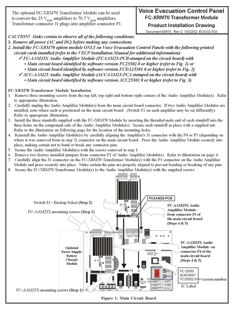
Fire-Lite
Fire-Lite FC-XRM70 Installation
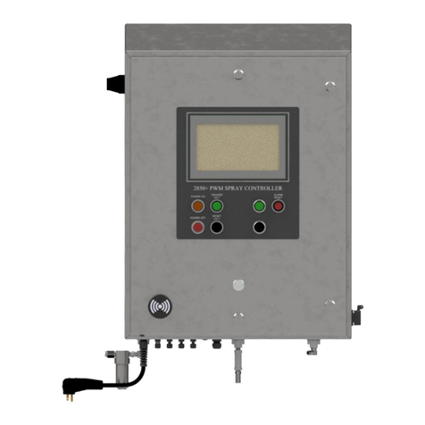
Spraying Systems
Spraying Systems AutoJet 2850+ owner's manual

TV One
TV One CC-300 CORIOconsole user guide

i3 International
i3 International i3C760 instruction manual

Fire Pro
Fire Pro 08451 quick start guide
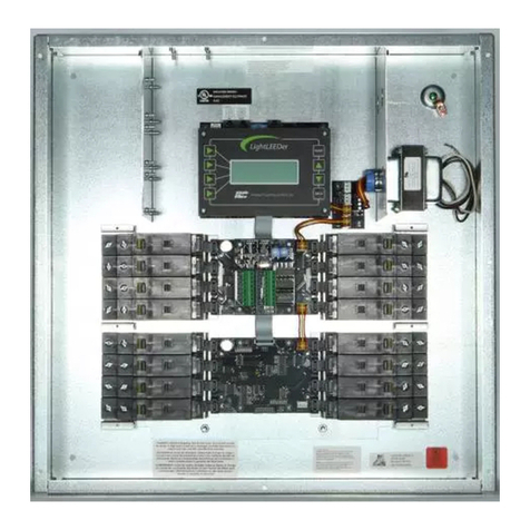
Intelligent Lighting Controls, Inc.
Intelligent Lighting Controls, Inc. LightLEEDer Operation manual
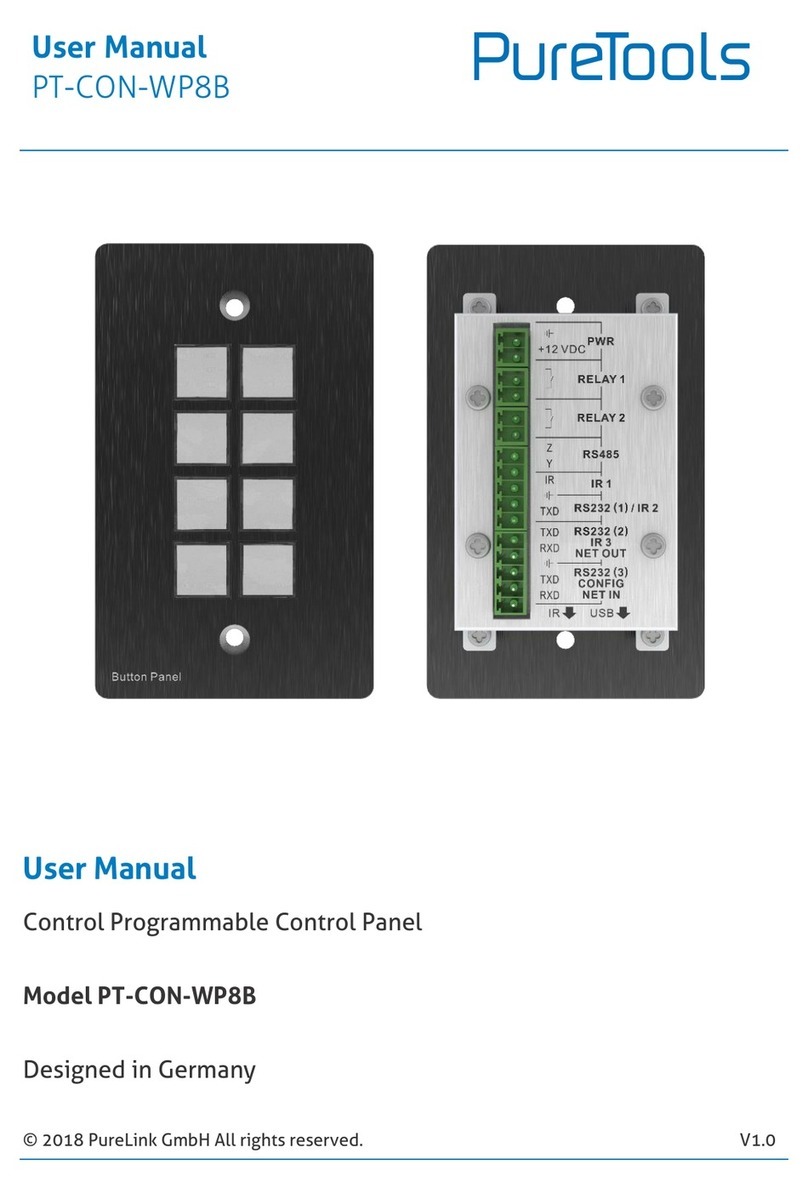
PureLink
PureLink PureTools PT-CON-WP8B user manual
IMG STAGE LINE
IMG STAGE LINE LED-4C instruction manual
Delta
Delta TP04G-AS2 instruction sheet
Paradox
Paradox SPECTRA 1727 installation manual
d & b audiotechnik
d & b audiotechnik R90 manual

