manuals.online logo
Brands
  1. Home
  2. •
  3. Brands
  4. •
  5. ProFlo
  6. •
  7. Plumbing Product
  8. •
  9. ProFlo PFWSC9867CP User manual

ProFlo PFWSC9867CP User manual

This manual suits for next models

2

Other ProFlo Plumbing Product manuals

ProFlo PFXCM6847CP User manual

ProFlo

ProFlo PFXCM6847CP User manual

ProFlo PFWSCM1M108 User manual

ProFlo

ProFlo PFWSCM1M108 User manual

ProFlo PF601BN User manual

ProFlo

ProFlo PF601BN User manual

ProFlo PFWSC4957CP User manual

ProFlo

ProFlo PFWSC4957CP User manual

ProFlo Roystone Series User manual

ProFlo

ProFlo Roystone Series User manual

ProFlo PFWS2840CP User manual

ProFlo

ProFlo PFWS2840CP User manual

ProFlo PFXC5012BN User manual

ProFlo

ProFlo PFXC5012BN User manual

ProFlo PF3870CP User manual

ProFlo

ProFlo PF3870CP User manual

ProFlo PFWSC3017CP User manual

ProFlo

ProFlo PFWSC3017CP User manual

ProFlo Apron User manual

ProFlo

ProFlo Apron User manual

ProFlo PFTS38CP User manual

ProFlo

ProFlo PFTS38CP User manual

ProFlo PFWSC6840CP User manual

ProFlo

ProFlo PFWSC6840CP User manual

ProFlo PF2830GCP User manual

ProFlo

ProFlo PF2830GCP User manual

ProFlo PFWSC2850CP User manual

ProFlo

ProFlo PFWSC2850CP User manual

ProFlo PFWSCM2A100 User manual

ProFlo

ProFlo PFWSCM2A100 User manual

ProFlo PFX3045 User manual

ProFlo

ProFlo PFX3045 User manual

ProFlo PFWSC4850CP User manual

ProFlo

ProFlo PFWSC4850CP User manual

ProFlo PF3800CP User manual

ProFlo

ProFlo PF3800CP User manual

ProFlo PFWSC2840CP User manual

ProFlo

ProFlo PFWSC2840CP User manual

ProFlo 500 User manual

ProFlo

ProFlo 500 User manual

ProFlo PFWSC1850CP User manual

ProFlo

ProFlo PFWSC1850CP User manual

ProFlo PFWSCM2M316 User manual

ProFlo

ProFlo PFWSCM2M316 User manual

ProFlo PFWSC6850ZBN User manual

ProFlo

ProFlo PFWSC6850ZBN User manual

ProFlo PFWSC1247ACP/ZBN User manual

ProFlo

ProFlo PFWSC1247ACP/ZBN User manual

Popular Plumbing Product manuals by other brands

Weka 506.2020.00E ASSEMBLY, USER AND MAINTENANCE INSTRUCTIONS

Weka

Weka 506.2020.00E ASSEMBLY, USER AND MAINTENANCE INSTRUCTIONS

American Standard DetectLink 6072121 manual

American Standard

American Standard DetectLink 6072121 manual

Kohler K-6228 Installation and care guide

Kohler

Kohler K-6228 Installation and care guide

Uponor Contec TS Mounting instructions

Uponor

Uponor Contec TS Mounting instructions

Pfister Selia 49-SL Quick installation guide

Pfister

Pfister Selia 49-SL Quick installation guide

Fortis VITRINA 6068700 quick start guide

Fortis

Fortis VITRINA 6068700 quick start guide

Kohler K-12183 Homeowner's guide

Kohler

Kohler K-12183 Homeowner's guide

Maxxus MX-M206-01 instruction manual

Maxxus

Maxxus MX-M206-01 instruction manual

Viega Prevista Pure 8512 Instructions for use

Viega

Viega Prevista Pure 8512 Instructions for use

Kohler Centerset K-15240 Homeowner's guide

Kohler

Kohler Centerset K-15240 Homeowner's guide

Viega Prevista Dry 8522.33 Instructions for use

Viega

Viega Prevista Dry 8522.33 Instructions for use

Sanela Lema SLP 59RB Instructions for use

Sanela

Sanela Lema SLP 59RB Instructions for use

Elkay EDF15AC Installation, care & use manual

Elkay

Elkay EDF15AC Installation, care & use manual

Hans Grohe AXOR Citterio E 36702000 Instructions for use/assembly instructions

Hans Grohe

Hans Grohe AXOR Citterio E 36702000 Instructions for use/assembly instructions

baliv WT-140 manual

baliv

baliv WT-140 manual

Kohler Mira Eco Installation & user guide

Kohler

Kohler Mira Eco Installation & user guide

BELLOSTA romina 0308/CC Installation instruction

BELLOSTA

BELLOSTA romina 0308/CC Installation instruction

Bristan PS2 BAS C D2 Installation instructions & user guide

Bristan

Bristan PS2 BAS C D2 Installation instructions & user guide

manuals.online logo
manuals.online logoBrands
  • About & Mission
  • Contact us
  • Privacy Policy
  • Terms and Conditions

Copyright 2025 Manuals.Online. All Rights Reserved.

TWO HANDLE LAVATORY FAUCET
MEZCLADORA PARA TINA LAVABO DE DOS / ROBINET DE LAVABO À DEUX POIGNÉES
PFWSC9867CP PFWSC9867ZBN PFWSC9867MB
Installation Instructions
Instrucciones de instalación / Instructions d'installation
ENGLISH
CAUTION-TIPS FOR REMOVAL OF
OLD FAUCET:
Always turn off water supply before
removing existing faucet or replacing
any part of the faucet. Open the
faucet handle to relieve water
pressure and ensure that water is
completely shut off.
CARE INSTRUCTIONS:
apply non-abrasive wax. Any
cleaners should be rinsed off
immediately. Do not use abrasive
cleaners on the faucet.
ESPAÑOL
PRECAUCIÓN-CONSEJOS PARA
CAMBIAR LA LLAVE MEZCLADORA:
Siempre corte el suministro de agua
antes de retirar el grifo actual o
remplazar cualquier pieza del mismo.
Abra la llave del grifo para liberar la
presión de agua y asegurar que ya no
corre agua.
INSTRUCCIONES DE CUIDADO:
Para conservar el acabado que cubre
las partes metálicas de su llave
mezcladora, aplique cera que no sea
abrasive, como una cera para autos. Si
usa algún tipo de limpiador, deberá
enjuagarlo inmediatamente. Los
abrasivos suaves son aceptables en
acabados platinum y LifeShine.
FRANÇAIS
ATTENTION-SUGGESTIONS POUR
ENLEVER L'ANCIEN ROBIENT:
Toujours couper l'alimentation en eau
avant d'enlever ou de démonter le
robinet. Ouvrir le robinet pour libérer la
pression d'eau et pour s'assurer que
l'alimentation en eau a bien été coupée.
DIRECTIVES D’ENTRETINE:
métalliques du robinet, appliquer une
cire non abrasive comme une cire à
votiure. Rincer immédiatement le
robinet aprés l'avoir nettoyé avec un
LifeShine peuvent être nettoyés à l'aide
de produits abrasifs doux.
1
You may need/Usted puede necesitar/
Aticles dont vous pouvez avoir besion
Goggles
Anteojos Protectores
Lunettes de sécurité
Wrench
Llave
Clé ajustable
Sealant Tape
Cinta Selladora
Ruban d'étanchéité
Silicone
Silicón
Silicone
SILICONE
05/30/22 REV.A FERGUSON.COM/PROFLO
Distributed Exclusively by Ferguson and Wolseley Canada
© 2022 Ferguson Enterprises, Inc. 0423 252402
Shut off water supplies.
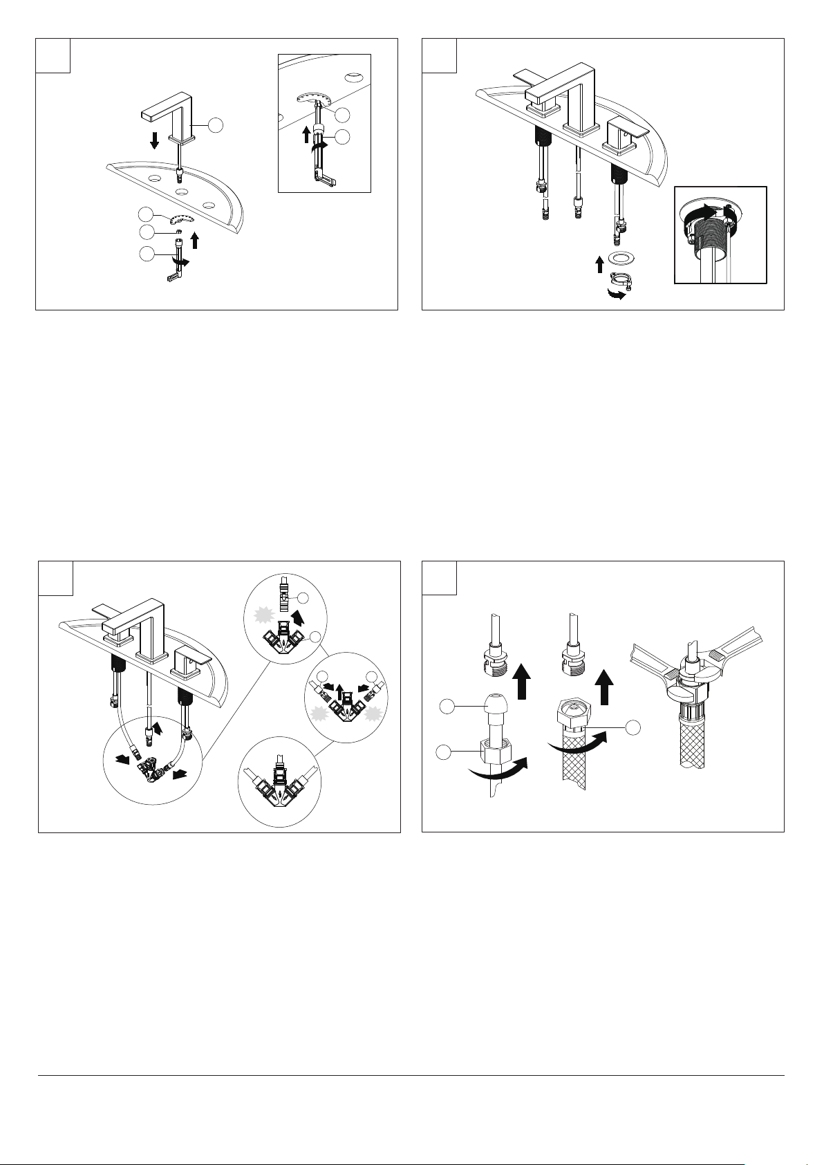
Place the faucet assembly (1) through the mounting hole in the sink. Secure the
faucet to the sink using the metal washer (2) and lock nut (3) provided. Tighten lock
nut (3) with spanner key (4) provided.
Slide hot and cold end valves through sink mounting holes. Make sure long tubes are
installed away from spout.
Note: Hot side end valve is labeled. Secure end valves with washers and nuts. Hand
tighten nuts onto shank. Lock nuts into position by tightening screws.
Desliza las válvulas para agua caliente y fría a través de los orificios de montaje del
lavamanos. Verifica que los tubos largos estén lejos del caño.
Nota: La válvula de agua caliente está etiquetada. Asegura las válvulas con
arandelas y tuercas. Asegura las tuercas al v stago, apretando con la mano. Fija las
tuercas en posición, apretándolas.
Insérez les robinets d'arrêts chaud et froid dans les trous de fixation du lavabo.
Veillez à ce que les longs tubes ne soient pas installés près du bec.
Remarque : Le robinet d'arrêt de l'eau chaude est étiqueté « chaud ». Fixez
fermement les robinets d'arrêt au moyen de rondelles et d'écrous. Serrez les écrous
à la main sur la tige de fixation. Placez les écrous de blocage dans la bonne position
en serrant les vis.
Cierra el suministro de agua.
Coloca el ensamblaje del grifo (1) en el orificio de montaje del lavamanos. Asegura el
grifo al lavamanos con la arandela (2) y contratuerca (3) suministradas. Ajusta la
contratuerca (3) con la llave inglesa (4) que se suministra.
Fermez les conduites d’alimentation en eau.
Placez le robinet (1) dans le trou de montage du lavabo. Fixez solidement le robinet
sur le lavabo à l’aide de la rondelle en métal (2) et du contre-écrou (3) fournis. Serrez
le contre-écrou (3) avec la clé à douille (4) fournie.
1 2
3
2
1
2
4
Make connections to water lines. Use 1/2" I. P. S. faucet connections (2) or use
supply line coupling nuts (3) with 3/8" O. D. ball-nose riser (1). Use wrenches to
tighten connections. Do not overtighten.
Conecta a las líneas de suministro. Usa conexiones de grifos de 1/2" I. P. S (2) o las
tuercas de acoplamiento de líneas de suministro incluidas (3) con un tubos
montantes de bola de diámetro exterior de 3/8" (1). Usa llaves para apretar las
conexiones. No aprietes demasiado.
Branchez l'alimentation en eau. Utilisez un raccord de robinet I. P. S (2) de 1,27 cm
(1/2 po) ou utilisez des écrous d'accouplement (3) pour conduite d'alimentation avec
colonne montante à embout arrondi au diamètre extérieur de 0,95 cm (3/8 po) (1).
Utilisez la clé pour serrer les raccords. Ne serrez pas trop.
4
3
4
3
(2 N.m
Max)
05/30/22 REV.A FERGUSON.COM/PROFLO
Distributed Exclusively by Ferguson and Wolseley Canada
© 2022 Ferguson Enterprises, Inc. 0423 252402
3
1
2
Click
Click Click
1
2
34
Attach the T-union (2) to the Spout (1) connection, the hot faucet handle (3)
connection, and cold faucet handle (4) connection. Push until the connections snap
together. Pull down moderately to ensure the connection has been made.
Fijar la unión T (2) a las conexiones de salida (1) y de las manijas para agua caliente
(3) y fría (4). Presionar hasta que las conexiones se aseguren entre sí. Halar hacia
abajo ligeramente para comprobar que la conexión es segura.
Fixez le raccord-union en T (2) sur le raccord du bec (1), le raccord de la manette
d’eau chaude du robinet (3) et le raccord de la manette d’eau froide du robinet (4).
Poussez jusqu’à ce que les raccords s’emboîtent . Tirez modérément vers le bas
pour vous assurer que le branchement est bien fait.
3
Before installation, unscrew the protective cap (1) from the horizontal rod (2). Insert the stopper (3) into the drain hole in the sink.
Insert the horizontal rod (2) into the drain body (4) and through the hole of the stopper (3) until you hear a click. See insert 2. You can press the two sides of the joint (5) to
remove the horizontal rod (2).
NOTE: For easier removal and cleaning, rotate the stopper (3) 90 degrees so that the horizontal rod (2) does not go through the hole in the stopper (3). See insert 3.
Insert the washer (2) into the drain flange (1) and place the drain flange (1) into the
drain hole of the sink. From underneath the sink, screw the drain body (6) onto the
drain flange (1). Ensure that the opening (a) for the ball rod on the drain body (6)
faces towards the rear of the sink. Tighten the rubber washer (3), metal washer (4)
and lock nut (5) on the drain body (6). Hand-tighten only.
5 6
7
1
2
3
4
1
1
2
3
4
4
5
6
a
Insert 3
Insert 2
1
2
3
1
2
3
44
2
5
5
Retira el tapón emergente (1), la brida del desagüe (2) y la arandela (3) del cuerpo
del desagüe (4).
Inserta la arandela (2) en la brida del desagüe (1) y coloca la brida (1)en el orificio de
desagüe del lavamanos. Desde abajo del lavamanos, enrosca el cuerpo del desagüe
(6) en la brida (1). Asegúrate de que la abertura (a) para la varilla de bola del cuerpo
del desagüe (6) esté hacia la parte posterior del lavamanos. Ajusta la arandela de
goma (3), la arandela de metal (4) y la contratuerca (5) en el cuerpo del desagüe (6).
Ajusta sólo con la mano.
Insérez la rondelle (2) sur la collerette d’écoulement (1) et placez la collerette
d’écoulement (1) dans l’orifice d’évacuation du lavabo. À partir du dessous du
lavabo, vissez le corps d’évacuation (6) sur la collerette d’écoulement (1).
Assurez-vous que l’ouverture (a) de la tige à rotule du corps d’évacuation (6) fait
face à l’arrière du lavabo. Serrez la rondelle en caoutchouc (3), la rondelle en métal
(4) et le contre-écrou (5) sur le corps d’évacuation (6). Serrez à la main uniquement.
Retirez la bonde mécanique (1), la collerette d’écoulement (2) et la rondelle (3) du
corps d’évacuation (4).
Antes de la instalación, desenrosca la tapa protectora (1) de la varilla horizontal (2). Inserta el tapón (3) en el orificio de desagüe del lavamanos.
Inserta la varilla horizontal (2) en el cuerpo del desagüe (4) y a través del orificio del tapón (3) hasta que escuches un clic. Ver inserto 2. Puedes presionar ambos lados de
la junta (5) para retirar la varilla horizontal (2).
NOTA: Para retirar y limpiar más fácilmente, gira el tapón (3) 90º de manera que la varilla horizontal (2) no atraviese el orificio del tapón (3). Ver inserto 3.
Avant l’installation, dévissez le capuchon de protection (1) de la tige horizontale (2). Enfoncez la bonde (3) dans l’orifice d’évacuation du lavabo.
Insérez la tige horizontale (2) dans le corps d’évacuation (4) et dans le trou de la bonde (3) jusqu’à ce que vous entendiez un déclic. Voir l’encart 2. Vous pouvez appuyer
sur les deux côtés du joint (5) pour retirer la tige horizontale (2).
REMARQUE : Pour faciliter le retrait et le nettoyage, tournez la bonde (3) à 90 degrés, de façon à ce que la tige horizontale (2) ne traverse pas le trou de la bonde (3). Voir
l’encart 3.
05/30/22 REV.A FERGUSON.COM/PROFLO
Distributed Exclusively by Ferguson and Wolseley Canada
© 2022 Ferguson Enterprises, Inc. 0423 252402
4
8
9
1
2
1
2
1
Slide the lift rod (1) down into the lift rod strap (2) through the faucet until it clicks
into the lift rod strap (2).
Hole
Press the horizontal rod (2) down to ensure the stopper (1) is in the maximum open position.
Slide the clip (4) upward, adjust the location of the lift rod strap (3) to the appropriate height and insert the horizontal rod (2) with the correct hole of the lift rod strap (3).
Move the lift rod strap (3) in or out to choose an appropriate location.
Slide the clip (4) downward until it secures with the horizontal rod (2).
12
33
4
4
5
1
3
2
4
4
1
3
2
4
1
3
2
4
Desliza la varilla de elevación (1) hacia abajo en la correa de la varilla (2) y a través
del grifo (A) hasta que haga clic dentro de la correa (2).
Faites glisser la tige de levage (1) vers le bas dans la courroie de la tige de levage (2)
à travers le robinet, jusqu’à ce qu’elle s’enclenche dans la courroie de la tige de levage (2).
Presiona hacia abajo la varilla (2) para garantizar que el tapón (1) quede completamente abierto.
Desliza la presilla (4) hacia arriba, ajusta la ubicación de la correa de la varilla de elevación (3) a la altura adecuada e inserta la varilla horizontal (2) con el orificio
correspondiente de la correa (3).
Mueve la correa de la varilla de elevación (3) hacia adentro o afuera para seleccionar la ubicación adecuada.
Desliza la presilla (4) hacia abajo hasta que la varilla horizontal (2) quede asegurada.
Poussez la tige horizontale (2) vers le bas pour assurer que la bonde (1) est dans la position ouverte maximale.
Faites glisser la pince (4) vers le haut, ajustez l’emplacement de la courroie de la tige de levage (3) à la hauteur appropriée, puis insérez la tige horizontale (2) dans le trou
correct de la courroie de la tige de levage (3).
Faites sortir ou rentrer la courroie de la tige de levage (3) pour choisir un emplacement approprié.
Faites glisser la pince (4) vers le bas jusqu’à ce qu’elle soit fixée fermement avec la tige horizontale (2).
05/30/22 REV.A FERGUSON.COM/PROFLO
Distributed Exclusively by Ferguson and Wolseley Canada
© 2022 Ferguson Enterprises, Inc. 0423 252402
5
10 11
12
Fig. 1 Fig. 2
21
1
a
b
If the pop up lift rod strap (1) is interfering with your installation, as shown in Fig. 1,
the lift rod strap (1) can be cut shorter.
Once you have identified the proper hole in the lift rod strap (1) that is necessary for
your installation, you may cut off the bottom portion (a) of the lift rod strap (1) by
snapping it off with pliers or cutting it off with a saw at the cutting point (b), as shown
in Fig. 2. Ensure the clip (2) does not slide off the lift rod strap (1).
Operate the lift rod (2) up and down to verify that the stopper (1) opens and closes
correctly.
1
2
Important: After installation is complete, remove aerator. Turn on water supply and
allow both hot and cold water to run for at least one minute each. While water is
running, check for leaks. Replace aerator. This flushes away any debris that could
cause damage to internal parts.
Si la presilla de la varilla de elevación (1) interfiere con tu instalación, como se muestra
en la Fig. 1, la presilla de la varilla de elevación (1) puede recortarse.
Una vez que hayas identificado el orificio adecuado en la presilla de la varilla de
elevación (1) que es necesario para tu instalación, puedes recortar la porción inferior (a)
de la presilla de la varilla de elevación (1) partiendo con alicates o cortando con una
sierra en el punto de corte (b), como se muestra en la Fig. 2. Asegúrate de que la
presilla (2) no se salga de la correa de la varilla de elevación (1).
Si la courroie de la tige de levage de l’évacuation mécanique (1) gêne votre installation,
comme illustré sur la Fig. 1, la courroie de la tige de levage (1) peut être raccourcie.
Une fois que vous avez identifié le bon trou de la courroie de la tige de levage (1)
nécessaire pour votre installation, vous pouvez couper la portion inférieure (a) de la
courroie de la tige de levage (1) en la cassant avec des pinces ou en la coupant avec
une scie au point de coupe (b), comme illustré sur la Fig. 2. Veillez à ce que la pince (2)
ne glisse pas de la courroie de la tige de levage (1).
Mueve la varilla de elevación (2) hacia arriba y abajo para verificar que el tapón (1)
se abre y cierra correctamente.
Déplacez la tige de levage (2) de haut en bas pour vérifier que la bonde (1) s’ouvre
et se ferme correctement.
Importante: Después de terminar la instalación, remueve el aireador. Abre el
suministro de agua y deja que corran el agua fría y caliente, cada una por un mínimo
de un minuto. Con el chorro abierto, verifica que no haya fugas. Coloca el aireador de
nuevo. Esto enjuaga cualquier suciedad que podría dañar las piezas internas.
Important : Une fois l’installation terminée, retirez l’aérateur. Ouvrez l’alimentation en
eau, et laissez couler l’eau chaude et l’eau froide pendant au moins une minute
chacune. Pendant que l’eau coule, vérifiez s’il y a des fuites. Remettez l’aérateur en
place. Ce rinçage chasse les débris éventuels qui pourraient endommager les pièces
internes.
05/30/22 REV.A FERGUSON.COM/PROFLO
Distributed Exclusively by Ferguson and Wolseley Canada
© 2022 Ferguson Enterprises, Inc. 0423 252402
* Specify Finish
Especifíque el Acabado
Précisez le Fini
6
Maintenance
If faucet leaks from spout outlet -Shut off water supplies-replace cartridge (1).
Note: Install cartridge (1) correctly for proper handle rotation.
Mantenimiento
Si la llave tiene filtraciones del pico del tubo de salida-Cierre los suministros de agua-Reemplace
el ensamble de la Unidad de la Espiga (1).
Note: Instale las espigas (1) correctamente para obtener una rotación debida.
Entretien
Si le robinet fuit par la sortie du bec-coupez l'eau puis remplacez l'obturateur (1).
Nota: Installer correctement les obturateurs (1) pour que les manettes tournent dans le bon sens.
OBPF5F30003
Aerator
Aireado
Aérateur
OBPF9F40002*
Lift rod & lift rod knob
Perilla de la varilla de extensión &
Varilla de elevación
Bouton & Tuge de Tige de levage
OBPF9F40003*
Pop-up assembly less lift rod
Ensamble del Desagüe
AutomáticoMenos la Barra de Alzar
Renvoi Mécanique en Plastique Sans
la Tige de Manoeuvre
1
OBPF7F13034*
Handle
Llave
Poignée
RP70765
Quick Connect Assembly
Ensamblaje Quick Connect
Ensemble de raccords rapides
OBPF220036
Cartridge C
Cartucho C
Cartouche C
OBPF220035
Cartridge H
Cartucho H
Cartouche H
05/30/22 REV.A FERGUSON.COM/PROFLO
Distributed Exclusively by Ferguson and Wolseley Canada
© 2022 Ferguson Enterprises, Inc. 0423 252402