manuals.online logo
Brands
  1. Home
  2. •
  3. Brands
  4. •
  5. PROFOLUX
  6. •
  7. Accessories
  8. •
  9. PROFOLUX S05 User manual

PROFOLUX S05 User manual

S05
Instruction
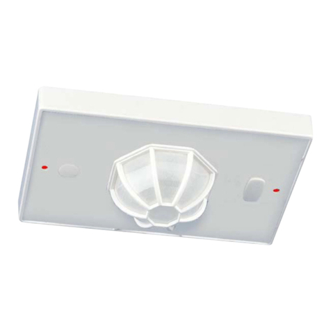
Welcome to use S05 infrared motion sensor!
The product adopts good sensitivity detector and integrated circuit. It gathers automatism,
convenience, safety, saving-energy and practical functions. It utilizes the infrared energy from
human as control-signal source and it can start the load at once when one enters detection field. It
can identify day and night automatically. It is easy to install and used widely.
SPECIFICATION:
Power Source: 220-240V/AC Detection Range: 360°
Power Frequency: 50/60Hz Detection Distance: 6m max(<24℃)
Ambient Light: <3-2000LUX (adjustable) Working Temperature: -20~+40℃
Time Delay: Min.10sec±3sec Working Humidity: <93%RH
Max.15min±2min Power Consumption: approx 0.5W
Rated Load: Max.2000W Installation Height: 2.2-4m
1000W Detection Moving Speed: 0.6-1.5m/s
FUNCTION:
Can identify day and night: The consumer can adjust working state in different ambient light. It
can work in the daytime and at night when it is adjusted on the “sun” position (max). It can work
in the ambient light less than 3LUX when it is adjusted on the “3” position (min). As for the
adjustment pattern, please refer to the testing pattern.
Time-Delay is added continually: When it receives the second induction signals within the first
induction, it will restart to time from the moment.
Good sensitivity Poor sensitivity
INSTALLATION ADVICE:
As the detector responds to changes in temperature, avoid the following situations:
Avoid pointing the detector towards objects with highly reflective surfaces, such as mirrors etc.
Avoid mounting the detector near heat sources, such as heating vents, air conditioning units,
light etc.
Avoid pointing the detector towards objects that may move in the wind, such as curtains, tall
plants etc.
CONNECTION:
Warning. Danger of death through electric shock!
Must be installed by professional electrician.
Disconnect power source.
Cover or shied any adjacent live components.
Ensure device cannot be switched on.
Check power supply is disconnected.
Please move the upper cover with anti-clockwise whirl as per the
diagram on the right.
Connect the power and the load according to the connection-wire
diagram.
Fix the bottom on the selected position with the inflated screw.
Install back the upper cover on the sensor, then you could switch on
the power and test it.
CONNECTION-WIRE DIAGRAM (See the right figure)
SENSOR INFORMATION:
TEST:
Turn the TIME knob anti-clockwise on the minimum
(10s).Turn the LUX knob clockwise on the maximum
(sun).
Switch on the power; the sensor and its connected
lamp will have no signal at the beginning. After
Warm-up 30sec, the sensor can start work .If the
sensor receives the induction signal, the lamp will turn on. While there is no another induction
signal any more, the load should stop working within 10sec±3sec and the lamp would turn off.
Turn LUX knob anti-clockwise on the minimum (3). If the ambient light is more than 3LUX, the
sensor would not work and the lamp stop working too. If the ambient light is less than 3LUX
(darkness), the sensor would work. Under no induction signal condition, the sensor should
stop working within 10sec±3sec.
Note: when testing in daylight, please turn LUX knob to (SUN) position, otherwise the
sensor lamp could not work! If the lamp is more than 60W, the distance between lamp and
sensor should be 60cm at least.
SOME PROBLEM AND SOLVED WAY:
The load does not work:
a. Please check if the connection of power source and load is correct.
b. Please check if the load is good.
c. Please check if the settings of working light correspond to ambient light.
The sensitivity is poor:
a. Please check if there is any hindrance in front of the detector to affect it to receive the
signals.
b. Please check if the ambient temperature is too high.
c. Please check if the induction signal source is in the detection field.
d. Please check if the installation height corresponds to the height required in the
instruction.
e. Please check if the moving orientation is correct.
The sensor can not shut off the load automatically:
a. Please check if there is continual signal in the detection field.
b. Please check if the time delay is set to the maximum position
c. Please check if the power corresponds to the instruction.
The wires come in and
out from the bottom
The wires come in and
out from the side
Height of installation:2-2.4m Detection Distance: Max.6m
Popular Accessories manuals by other brands

BRASS MONKEY GH1970 instruction manual

BRASS MONKEY

BRASS MONKEY GH1970 instruction manual

Generac Power Systems Air-Cooled Generator Sets 5621 specification

Generac Power Systems

Generac Power Systems Air-Cooled Generator Sets 5621 specification

Homelite 18775 Assembly instructions

Homelite

Homelite 18775 Assembly instructions

Vision ZD2301IN-5 Installation & operation manual

Vision

Vision ZD2301IN-5 Installation & operation manual

Linocell Qi 10000 manual

Linocell

Linocell Qi 10000 manual

Bresser Lunt-Solar-Systems Crayford focuser with... manual

Bresser

Bresser Lunt-Solar-Systems Crayford focuser with... manual

Calex PyroCAN Series Operator's guide

Calex

Calex PyroCAN Series Operator's guide

Eurotronic Z-Wave Plus instructions

Eurotronic

Eurotronic Z-Wave Plus instructions

IFM LX Series operating instructions

IFM

IFM LX Series operating instructions

ELICA Marie Operation manual

ELICA

ELICA Marie Operation manual

Smartwares Byron DIC-23112 manual

Smartwares

Smartwares Byron DIC-23112 manual

RUBYTEC Kea quick start guide

RUBYTEC

RUBYTEC Kea quick start guide

Stramatel FRC Technical Data and Installation Instructions

Stramatel

Stramatel FRC Technical Data and Installation Instructions

Micronor sensor MR660 Series instruction manual

Micronor

Micronor sensor MR660 Series instruction manual

Woody Valley Wani light 2 owner's manual

Woody Valley

Woody Valley Wani light 2 owner's manual

PCB Piezotronics IMI SENSORS 640B11 Installation and operating manual

PCB Piezotronics

PCB Piezotronics IMI SENSORS 640B11 Installation and operating manual

X-Moove Mini10 user guide

X-Moove

X-Moove Mini10 user guide

Yamaha FC7 owner's manual

Yamaha

Yamaha FC7 owner's manual

manuals.online logo
manuals.online logoBrands
  • About & Mission
  • Contact us
  • Privacy Policy
  • Terms and Conditions

Copyright 2025 Manuals.Online. All Rights Reserved.