Profoto ProDaylight 200Air User manual

ProDaylight200Air
ProDaylight400Air
ProBallast200/400
User´s Guide EN
This user guide is available in other languages at profoto.com/support
CN – 其他语言版本的用户指南可从profoto.com/cn/support下载
DE–DasBedienungs-HandbuchisauchinanderenSprachenverfügbarunterprofoto.com/de/support
ES – Esta guía de usuario está disponible en otros idiomas en profoto.com/support
FR – Ce manuel d’utilisation est également disponible en d’autres langues sur profoto.com/fr/support
IT – Questa guida per gli utenti è disponibile in altre lingue su profoto.com/it/support
JP – このユーザーガイドはprofoto.com/ja/supportに他の言語でもご用意しています。
RU – Инструкция пользователя на других языках доступна на profoto.com/ru/support
ProDaylight 200/400 Air
2
www.profoto.com

ProDaylight 200/400 Air
3
www.profoto.com
Thank you for choosing Profoto
Thanks for showing us your confidence by investing in a
ProDaylight Air unit. For more than four decades we have
sought the perfect light.What pushes us is our conviction that
we can offer even yet better tools for the most demanding
photographers.
Before our products are shipped we have them pass an
extensive and strict testing program. We check that each
individual product comply with specified performance,quality
and safety. For this reason our equipment is widely used in
rentalstudiosandrentalhousesworldwide,fromParis,London,
Milan,NewYork andTokyo to CapeTown.
Some photographers can tell just from seeing a picture,if
Profotoequipmenthasbeenused.
Professional photographers around the world have come to
value Profoto’s expertise in lighting and light-shaping. Our
extensive range of Light Shaping Tools offers photographers
unlimitedpossibilitiesforcreatingandadjustingtheirownlight.
Everysinglereflectorandaccessorycreatesitsspeciallightand
theuniqueProfotofocusingsystem offersyouthepossibilityto
create your own light with only a few different reflectors.
Enjoy your Profoto product!
ProDaylight 200/400 Air
4
www.profoto.com
SAFETY PRECAUTIONS!
Read and follow all safety instructions below carefully to avoid injuries or damages! Make sure that
Profoto Safety Instructions is always accompanied the equipment! Profoto products are intended for
professionaluse! Theequipmentisonly intended for indoor photographicorfilminguse. Donotplaceor
usethe equipmentwhere it can be exposed to moisture,extreme electromagnetic fieldsor in areas with
flammablegasesordust! Donotusetheequipmentinambienttemperaturehigherthan+35°C(+95°F).
Do not expose the equipment to dripping or splashing. Do not place any objects filled with liquids on or
neartheequipment. Donotexposetheequipmenttohastytemperature changes in humid conditions as
thiscouldleadtocondensationwater intheunit. Donotconnectthisequipmenttoequipmentfromother
brands.Only use ballast,lamps and light shaping tools as specified by Profoto.Do not use lamp without
supplied protective glass covers or protective grids. Do not stare directly at lamp while in operation.
Minimum distance to flammable surfaces is 400 cm in front of the lamp. Limit exposure in front of the
lamp if used at close distances.Glass covers shall be changed if they have become visibly damaged to
suchanextentthattheireffectivenessisimpaired,forexamplebycracksordeepscratches. Lampsshall
be changed if they are damaged or thermally deformed. When placing a lamp into the holder ensure not
totouch the bulb with bare hands. Equipment mustonly be serviced,modified or repaired by authorized
and competent service personnel!
WARNING – Electrical Shock – High Voltage!
The equipment shall always be connected to grounded mains power supply outlet! Only use Profoto
extensioncablesandmainscables!Donotopenordisassembleballastorlamphead!Equipmentoperates
with high voltage.Disconnect lamp head cable between ballast and lamp head when changing bulb!
Caution – Burn Hazard – Hot Parts!
Donot touch hot partswith bare fingers! Bulb,protective glass coverand certain metal partsemit strong
heatwhenused!Reflectorpartsmayreachatemperatureof+200°C(+392°F). When thelamphasbeen
inuse,wait10minutesbeforeremovingtheprotectiveglasscover.Donotpointlamptooclosetopersons.
All lamps may on rare occasions explode and throw out hot particles!
NOTICE – Equipment Overheating Risk
Removetransportcapfromlampheadbeforeuse!Donotobstructventilationbyplacingfilters,diffusing
materials,etc.overinlets and outlets of theequipment ventilationor directly over protective glasscover.
Note about RF!
This equipment makes use of the radio spectrum and emits radio frequency energy.Proper care should
betakenwhenthedeviceisintegratedinsystems.Makesurethatallspecificationswithinthisdocument
arefollowed,especiallythoseconcerningoperatingtemperatureandsupplyvoltagerange.Makesurethe
device is operated according to local regulations.The frequency spectrum this device is using is shared
with other users.Interference can not be ruled out.
Final Disposal
Equipment contains electrical and electronic components that could be harmful to the environment.
Equipment may be returned to Profoto distributors free of charge for recycling according to WEEE.
Follow local legal requirements for separate disposal of waste, for instance WEEE directive for
electrical and electronic equipment on the European market, when product life has ended!
Safety instructions

ProDaylight 200/400 Air
5
www.profoto.com
Table of Contents
Safety instructions....................................................................................................4
System description ...................................................................................................7
Profoto Air ...................................................................................................7
Nomenclature...........................................................................................................8
Functionality.............................................................................................................9
Metal halide lamp........................................................................................9
Glass cover..................................................................................................9
Reflector......................................................................................................9
Cooling system..........................................................................................10
Built-in timer .............................................................................................10
ProBallast...............................................................................................................11
Power supply.............................................................................................12
Frequency mode........................................................................................12
Light intensity............................................................................................12
Remote control..........................................................................................12
Operating instructions.............................................................................................13
Stand mounting.........................................................................................13
Remove protecting cap..............................................................................13
Changing glass cover ................................................................................13
Reflector mounting ....................................................................................14
Power connection......................................................................................14
Radio settings............................................................................................14
Frequency mode setting.............................................................................15
Adjusting light intensity..............................................................................15
Read out timer value..................................................................................15
Changing settings in standby mode ...........................................................15
Turn unit off ..............................................................................................15
Remote control .......................................................................................................16
Turn unit on/off .........................................................................................16
Light intensity setting ................................................................................16
Maintenance...........................................................................................................17
Changing lamp ..........................................................................................17
Changing fuse ...........................................................................................17
Trouble shooting .....................................................................................................18
List of compatible Profoto Light Shaping Tools ........................................................19

ProDaylight 200/400 Air
6
www.profoto.com
Technical data ........................................................................................................20
ProDaylight Air...........................................................................................20
ProBallast 200/400....................................................................................20
Warranty.................................................................................................................21
Regulatory information ...........................................................................................22
United States and Canada..........................................................................22
Japan........................................................................................................23

ProDaylight 200/400 Air
7
www.profoto.com
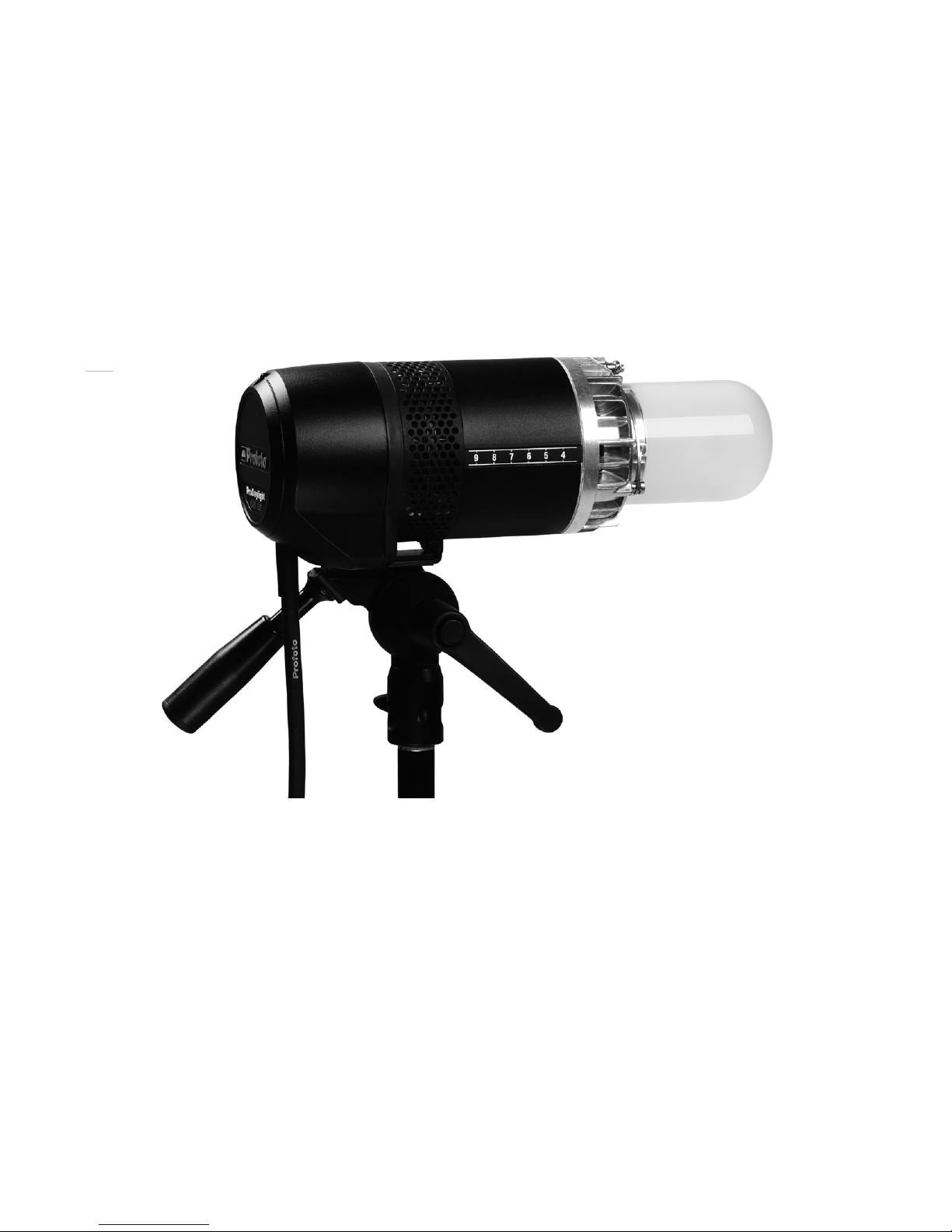
System description
ProDaylightAir is a metal halide based (HMI type) continuous light source.The powerful metal
halidelampprovidesdaylightcolortemperature,whichisidealformanyphotoandvideoshoots.
TheProDaylightAirisdesigned forheavy-dutyuse.Itsmetal housingandallcomponents
are solid,reliable and withstand even the most demanding shooting situations.
The ProDaylightAir product family includes the following lamps:
• ProDaylight200Air
• ProDaylight400Air
• ProDaylight800Air
TheProDaylight200AirandProDaylight400AirarepoweredfromtheProBallast200/400,
a flicker-free multi-voltage electronic ballast. The ProBallast 200/400 is also used to
control the ProDaylight 200Air and ProDaylight 400Air lamps.
As a professional photographer or videographer, you have your own special style and
needs. Profoto’s Light Shaping Tools – including the new line of Light Shaping Tools for
Video Lights – fit perfectly with the ProDaylight 200Air and ProDaylight 400Air,enabling
you to shape the light your own way.
For more information about the ProDaylight 800 Air, please refer to the ProDaylight 800
Air User’s Guide.
ProfotoAir
ProfotoAirisasystemforconvenientremotecontrolofflashgeneratorsandstudiolamps.
The Profoto Air system is operating on one of eight selectable radio channels on the 2.4
GHzradio frequencyband,forworld wide use.ProfotoAirallowscontrol of yourlight from
as far away as 300 m/1000 ft (free line of sight).
TheProfotoAirradiosystemisfullyintegratedintheProBallast200/400,allowingwireless
remote control of the ProDaylight 200Air and ProDaylight 400Air units.
ProfotoAirRemote
TheProfotoAirRemotedeviceoffersremotecontrolofyourProDaylightAirunit.Thedevice
controlspracticallyaninfinitenumberofProDaylightAirunitsinuptosixgroups,eitherall
at once in Master mode,or in individual groups.
ProDaylight 200/400 Air
8
www.profoto.com
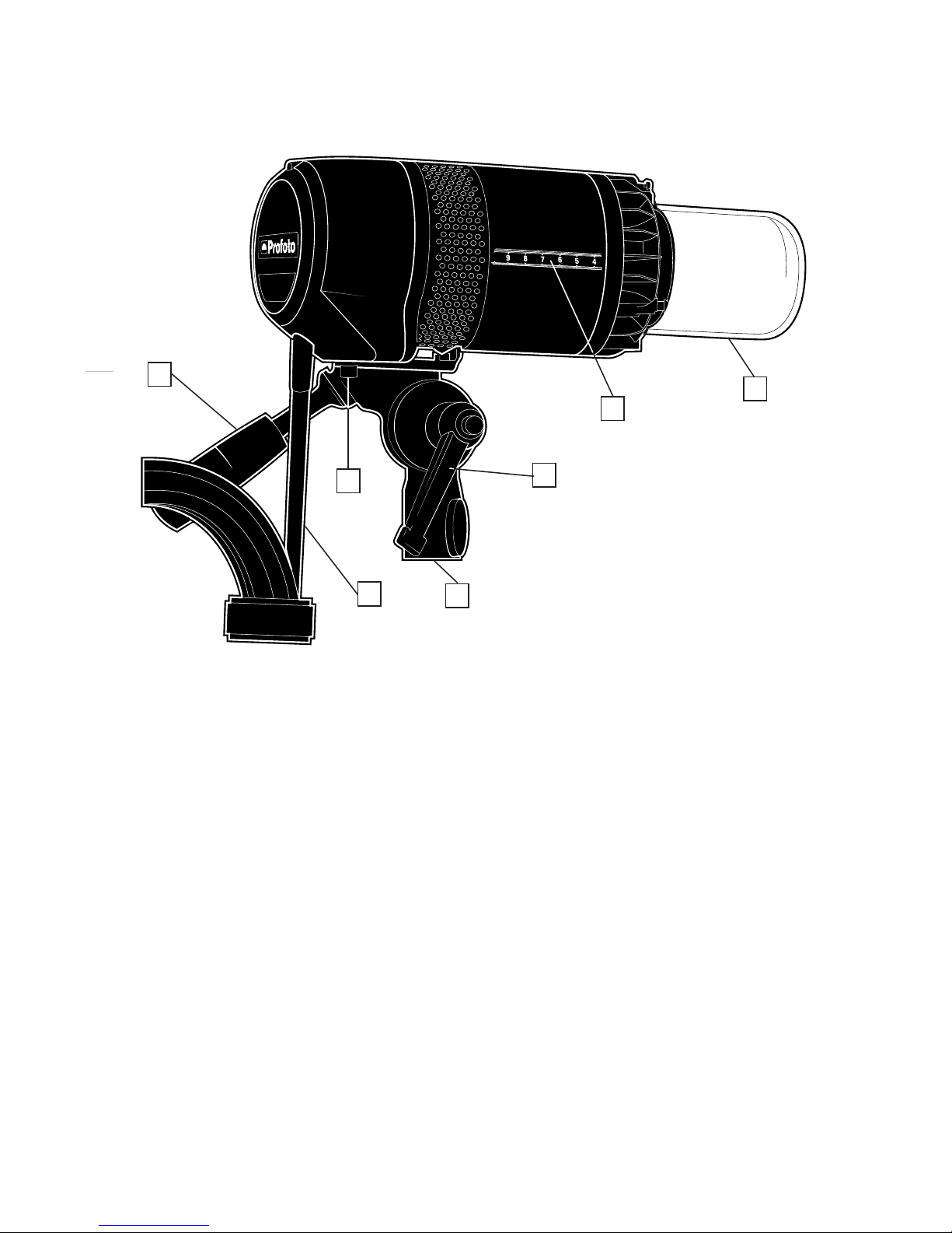
Nomenclature
1
2
34
5
67
1. Handle
2. Bracket Screw
3. Lamp Cable
4. StandAdapter
5. Locking Handle
6. Zoom Scale
7. Protective glass cover

ProDaylight 200/400 Air
9
www.profoto.com
Functionality
Metalhalidelamp
TheProDaylightAirunit isequippedwithapowerfulmetalhalidelamp,providingdaylight
color temperature.
SAFETY PRECAUTION!
Profoto only uses UV-doped CSR-lamps,which emit a fraction of the hazardous UV radiation compared to classic
HMItype lamps.Never use other types oflamps thanthe onesspecified byProfoto.
A cold metal halide lamp does not immediately begin producing its full light capacity.The
warm up period can be a few minutes.During that time,the color of the light may vary.
If the ProDaylightAir unit is turned off, it takes about two minutes before the warm lamp
canbeturnedonagain.Itisrecommendedtoletthelamprunforatleast15minutesafter
turning it on, since turning the lamp on and off repeatedly considerably reduces the life
time of the lamp.
Glasscover
Metalhalide lampsoperate underhigh pressureandtemperature,whichcalls forspecial
safety measures.The ProDaylight Air unit is equipped with a protective glass cover that
protectsfromlampshatteringandUVradiation.Iftheglasscoverisnotcorrectlymounted
(see page 12),it is not possible to turn on the ProDaylightAir unit and“LAMP”is shown in
the Display [F] on the ProBallast 200/400.
SAFETY PRECAUTION!
Adamaged(crackedorscratched)glasscovermustneverbeused!ThelevelofUVprotectionprovidedbytheglass
coveris matched tothe lamptype specifiedby Profoto.Only use Profoto specified lamps.
The protective glass cover is available in different versions; with frosted and clear glass.
Reflector
By mounting a reflector and placing it in different positions, using the Zoom Scale [6],
several light characteristics can be created for each lighting purpose.The unique rubber
collar fastening system provides secure and rapid handling of the reflectors, also when
hot.

ProDaylight 200/400 Air
10
www.profoto.com
Coolingsystem
The ProDaylight Air unit is equipped with effective cooling, designed for optimal cooling
without fan.
The cooling system includes automatic overheating protection.If the temperature of the
ProDaylight Air unit exceeds maximum set levels, the ProDaylight Air unit will be turned
off and“HOT”will be shown in the Display [F] on the ProBallast 200/400.This automatic
protection will only interfere under extreme conditions, such as when the air vents are
blocked.
Built-intimer
The ProDaylightAir unit has a built-in timer,which can be read out in standby mode.The
timer feature is included to make it easier to keep track of lamp life.
ProDaylight 200/400 Air
11
www.profoto.com
ProBallast
Metalhalide lamps requireanelectronic ballast todeliverthe proper voltage andcurrent.
The ProBallast 200/400 is a flicker-free electric ballast used to power the ProDaylight
200AirandProDaylight 400Air.The ProBallast200/400has a passive coolingsystemfor
quiet operation.
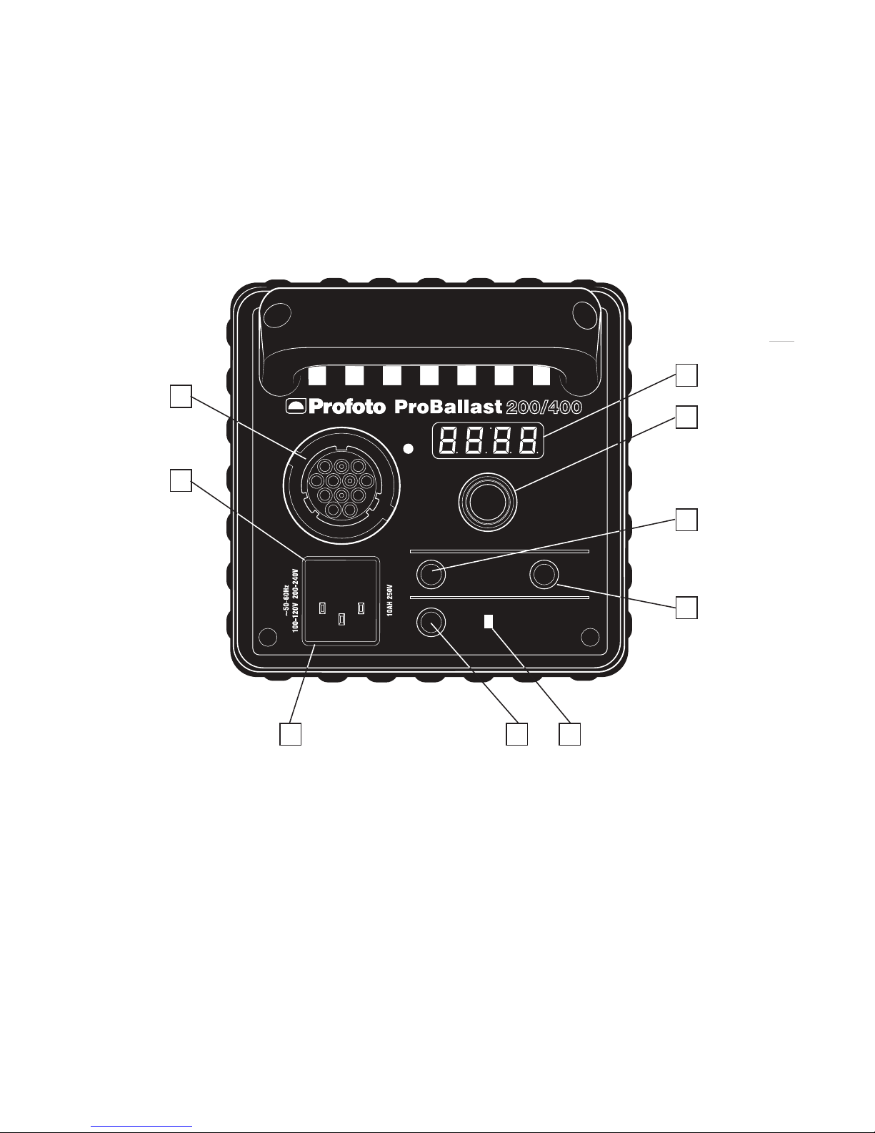
TheProBallast200/400alsoincludesacontrolpanelforcontroloftheProDaylight200Air
and ProDaylight 400Air.
A
B
C D E
F
G
CHANNEL SET
ON
MODE
H
I
A. Lamp Connector
B. Fuse Holder
C. Power Connector
D. On/Off Button
E. Power Indicator
F. Display
G. Setting Knob
H. Channel Set Button
I. Mode Button

ProDaylight 200/400 Air
12
www.profoto.com
Power supply
The ProBallast 200/400 can be connected to 95-265 VAC, 50-60 Hz. The ballast
automaticallysensesandadaptstothesuppliedvoltageandfrequency.Thepowersupply
fuses must be as specified in the section Technical data.
Frequencymode
The frequency of the output voltage is switchable between 50 Hz (silent),100 Hz (flicker
free) and 300 Hz (high speed). A higher frequency will allow higher frame rates (fps)
during video shoots without flicker. The Mode Button [I] is used to select the frequency
mode setting.
Lightintensity
The current light intensity of the ProDaylightAir is shown in the Display [F],in percent (%)
ofmaximumlightoutput.TheSettingKnob[G]isusedtoadjustthelightintensity,in1%or
10% increments.The light intensity can be adjusted between 50 and 100%.
Remotecontrol
TheProfotoAirradiosystemisfullyintegratedintheProBallast200/400,allowingwireless
remote control of the ProDaylightAir unit.
Withthe ProfotoAir Remote device,theProDaylightAir unit can beturned on/off remotely
and the light intensity can be adjusted. With the Profoto Studio Air software, multiple
lighting setups including numerous continuous lights and flash units can be created and
coordinated.
For more information about remote control,please refer to the User’s Guides for Profoto
Air Remote or ProfotoAir USB/Profoto StudioAir.
ProDaylight 200/400 Air
13
www.profoto.com
Operating instructions
Standmounting
1. Mount and fasten the ProDaylight Air unit on the stand using the locking knob on the
StandAdapter [4].
2. The unit can be directed upwards/downwards when the Locking Handle [5] is
loosened.Fasten the Locking Handle [5] when the unit is correctly directed.
Foralternativewaysofmounting,theProDaylightAirunitcanberemovedfromthebracket
by unscrewing the 5 mm hex socket Bracket Screw [2].
Remove protecting cap
1. Unlock the clasp on the protecting cap.
2. Gently remove the protecting cap from the ProDaylightAir unit.
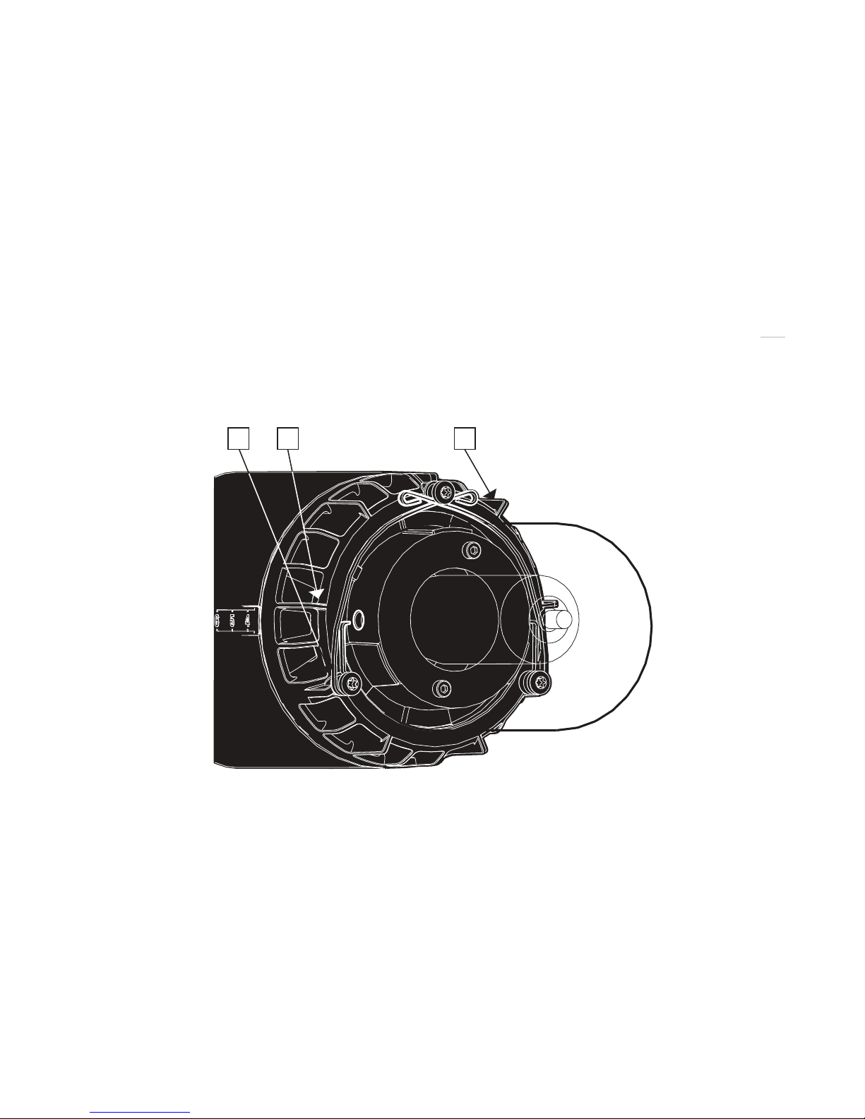
Changingglasscover
iii ii i
1. Ensure that the ProDaylight Air unit is turned off and that the Lamp Cable [3] is not
connected.
2. IftheProDaylightAirunithasbeeninuse,waitfortheunittocooldownoruseprotective
gloves.
3. Unlock the glass cover by pressing down the safety pins [i] and then pulling them out
one by one.
4. Gently remove the glass cover and fit the new glass cover in place.
5. Make sure that the safety switch [ii] is pressed down and that both safety pins fit
properly into the slots [iii] on each side of the glass cover.
6. Secure the glass cover by pressing the safety pins down and then pushing them one
by one under the top screw.

ProDaylight 200/400 Air
14
www.profoto.com
Reflectormounting
1. Unlock the clasp on the reflector.
2. Slide the reflector onto the ProDaylight Air unit. Use the Zoom Scale [6] to place the
reflector in the desired position.
3. Secure the reflector by locking the clasp.
Power connection
1. Connect the Lamp Cable [3] to the Lamp Connector [A] on the ProBallast 200/400 by
aligningthewhitedotsonthecableplugwiththewhitedotontheballastpanel.Secure
by turning the ring on the plug clockwise.
2. ConnecttheACmainscabletothePowerConnector[C]ontheProBallast200/400and
to the mains power supply outlet.
3. ThePower Indicator[E] will be red,indicating thatthe ballast is receivingpowerbutis
in standby mode.
4. Press the On/Off Button [D] to turn on the ProBallast 200/400 and the ProDaylightAir
unit.
5. The Power Indicator [E] will now be green.
Radiosettings
1. PresstheChannelSetButton[H].TheDisplay[F]willstartflashing,showingthecurrent
radio channel number to the left and the radio group letter to the right, or “off” if the
radio transceiver is switched off.
2. While the Display is flashing, turn the Setting Knob [G] to switch on/off the radio
transceiver and to select radio channel number (off,1,2,3,4,5,6,7,8):
• TurntheSettingKnob[G]clockwisetoswitchontheradiotransceiverandincrease
the radio channel number.
• TurntheSettingKnob[G]counter-clockwisetodecreasetheradiochannelnumber
and to switch off the radio transceiver.
3. While the Display is flashing, press and hold down and turn the Setting Knob [G]
clockwise to increase the group letter (A, B, C, D, E, F) and counter-clockwise to
decrease the letter.
4. WaituntiltheDisplay[F]stopsflashing.(TheDisplaywillnowshowthelightintensity.)

ProDaylight 200/400 Air
15
www.profoto.com
Frequencymode setting
A higher frequency will allow higher frame rates (fps) during video shoots without flicker.
1. PresstheModeButton[I].TheDisplay[F]willshowthecurrentfrequencymodesetting.
2. Turn the Setting Knob [G] to change the frequency mode settings; 50 Hz (silent),100
Hz (flicker free) and 300 Hz (high speed).
Adjustinglightintensity
Use the Setting Knob [G] to adjust the light intensity:
• TurntheSettingKnob[G]clockwisetoincreasethelightintensityin1%increments
and counter-clockwise to decrease.
• PressandholddowntheSettingKnob[G]andturntheknobclockwisetoincreasethe
energy in 10% increments and counter-clockwise to decrease.
Readouttimervalue
To read out the timer value of the lamp head,the ProDaylightAir unit has to be connected
to the ProBallast 200/400 and the ProBallast 200/400 must be in standby mode.
1. Press and hold the Setting Knob [G] for 1 second,then release the knob.
2. The Display [F] will show the timer value in hours. If no lamp head is connected, the
Display [F] will show“----“.
Changingsettingsinstandbymode
All settings can be reached and changed in standby mode.A short press on the Setting
Knob [G] will light up the Display [F] and make it possible to view and change settings.
Turn unit off
1. Press the On/Off Button [D] to turn off the ProDaylight Air unit and the ProBallast
200/400.
2. ThePowerIndicator[E]ontheProBallast200/400willbered,indicatingthattheballast
is receiving power but is in standby mode.
3. Disconnect theAC mains cable on the ProBallast 200/400 device from mains power.

ProDaylight 200/400 Air
16
www.profoto.com
Remote control
ForremotecontrolusingProfotoAirRemote,thesameradiochannelandgrouphavetobe
set on the ProBallast 200/400 and the ProfotoAir device.
ForremotecontrolusingProfotoAirUSBandProfotoStudioAir,thesameradiochannelhas
to be set on the ProBallast 200/400 and in the Profoto StudioAir program.
For radio channel and group settings on the ProfotoAir devices and the Profoto StudioAir
program,please refer to the corresponding User’s Guide.
Turn unit on/off
Use the Head or Model Buttons (1) and (0) on the Profoto Air Remote device to turn the
ProDaylightAir unit on and off.
Lightintensitysetting
UsetheEnergyButtons (+) and (-) ontheProfotoAir Remote device to increase/decrease
the light intensity:
• PresstheEnergyButton<2secondstoincrease/decreasein1%increments.
• PresstheEnergyButton>2secondstoincrease/decreasein10%increments.

ProDaylight 200/400 Air
17
www.profoto.com
Maintenance
Changinglamp
1. Ensure that the ProBallast 200/400 is turned off and that the Lamp Cable [3] is not
connected.
2. If the ProDaylightAir unit has been in use,wait for the unit to cool down.
3. Unlocktheglasscoverbypressingthesafetypinsdownandthenpullingthemoutone
by one,see figure on page 13.
4. Gently remove the glass cover.
5. Pullthe lamp straightoutof the socket.Alwaysuse protective gloveswhendoing this.
6. Insert a new modeling lamp,straight into the socket.Do not touch the lamp with bare
hands.
7. Gently fit the glass cover in place.
8. Makesurethatthesafetyswitchispresseddownandthatbothsafetypinsfitproperly
into the slots on each side of the glass cover,see figure on page 13.
9. Secure the glass cover by pressing the safety pins down and then pushing them one
by one under the top screw.
Changingfuse
There are two exchangeable fuses in the ProBallast 200/400.
1. Disconnect the ProBallast 200/400 fromAC mains power.
2. Pull out the Fuse Holder [B] and remove the old fuses.
3. GentlypushthenewfusesallthewayintotheFuseHolder[B].Onlyusefusesspecified
in section Technical data.
4. Gently push the Fuse Holder [B] in place.

ProDaylight 200/400 Air
18
www.profoto.com
Trouble shooting
Symptom Diagnose Action
Power
Indicator [E] not
illuminated
Bad connection to the
ballast orAC mains.
• CheckthattheLampCable[3]and
theAC mains cable are correctly
connected.
Internal fuse defect. • CheckthefusesontheProBallast
200/400.If the problem remains
after replacing the fuses,contact
your nearest Profoto service
station.
ProDaylightAir
is not turned
on when On/
Off Button [D]
is pressed and
“LAMP”is
shown in the
Display [F].
A safety switch prevents
the lamp from being
turnedonif the glass cover
is not in place.
Fit the glass cover correctly in place,
see instructions on page 13.
ProDaylight
Air turns off
automatically
and“HOT”is
shown in the
Display [F].
The unit is overheated. • Ensurebetterventilation.
• Waituntilthetemperature
decreases before the unit is
turned on again.
• Iftheproblemremainsplease
contact your nearest Profoto
service station.

ProDaylight 200/400 Air
19
www.profoto.com
List of compatible Profoto Light Shaping Tools
The ProDaylight 200 Air and ProDaylight 400 Air can be used in combination with the
following Profoto light shapers:
• HRSoftboxes
• HRLanterns,exceptHRLantern1.7’FLAT(Max400W)
• ProCinereflectorincludinglenses
• Softlightreflector
• Magnumreflector
• Zoomreflector
• Narrowbeamreflector
• Narrowbeamtravelreflector
• WideZoomreflector
• TeleZoomreflector
• ProTube
• Discreflector
• Gridreflector
• ProFresnelSpot
• ProfotoGiantreflectors(parabolic)
• ProfotoSilverumbrellas(withProCinereflectoronly)
• ProfotoTranslucentumbrellas(withProCinereflectoronly)
• ProfotoWhiteumbrellas(withProCinereflectoronly)
• Grids
• Standardsoftboxes
• Hardbox
• Snoot
• Gridandfilterholder
TheProDaylight200AirandProDaylight400Airarenotrecommendedtobeusedwiththe
following Profoto Light shapers:
• ProBox
• SpotSmall
• ProGlobe
• FresnelSmall

ProDaylight 200/400 Air
20
www.profoto.com
Technical data
ProDaylightAir
ProDaylight200Air ProDaylight400Air
Wattage 200W 400W
Lamp type GE CSR 200/SE/HR/UV-C GE CSR 400/SE/HR/UV-C
Socket type GZY9.5 GZZ9.5
Lamp life 200 hours 750 hours
Nominal color temperature 6000 K 5900 K
Dimensions 30 x 10 x 11 cm (11.8 x 3.9 x 4.3 in)
Weight (incl.cable) 2.5 kg (5.5 lbs)
ProBallast200/400
Lamp wattage 200/400W
Input voltage/frequency Automatic sensing:95-265VAC,50/60 Hz
Fuse 10A,Fast acting type,5 x 20 mm
Power factor correction (PFC) Yes
Power factor 0.98
Dimming 50-100 %
Cooling Passive
Lamp output 100 Hz (Flicker-free)
300 Hz (High speed)
50 Hz (Silent)
Dimensions 31.5 x 14.5 x 14.5 cm (12.4 x 5.7 x 5.7 in)
Weight 4.2 kg (9.3 lbs)
All data are to be considered as nominal and Profoto reserves the right make changes
without further notice.
This manual suits for next models
2
Table of contents
Other Profoto Lighting Equipment manuals


