Profound TULSA-PRO Transurethral Ultrasound Ablation... User manual

Transurethral Ultrasound Ablation
System
Operator’s Manual
General Electric MR750w 3T

Publisher’s Notice
TULSA-PRO® Operator’s Manual
- GE MR750w 3T
111229B
Page 2 of 130
Publisher’s Notice
TULSA-PRO® SYSTEM
Model Number: PAD-105
Operator’s Manual for General Electric MR750w 3T
Document Number: 111229 REV B
Change Control Number: CO-05697
Published By:
Profound Medical Inc.
2400 Skymark Avenue, Unit 6
Mississauga ON L4W 5K5
Phone: 647-476-1350
Fax: 647-847-3739
http://www.profoundmedical.com
EUROPEAN AUTHORIZED REPRESENTATIVE:
MDSS GmbH
Schiffgraben 41
30175 Hannover, Germany
Tel.: +49 511 6262 8630
Fax: +49 511 6262 8633
www.mdss.com
Copyright © 2022 Mississauga, Canada.
All rights reserved. No part of this document may be reproduced or transmitted in any form or by
any means, electronic, mechanical, photocopying, recording, or otherwise, without prior written
permission from Profound Medical Inc.
Federal law restricts this device to sale by or on the order of a Physician.

Table of Contents
TULSA-PRO® Operator’s Manual
- GE MR750w 3T
111229B
Page 3 of 130
Table of Contents
PUBLISHER’S NOTICE...................................................................................................................2
TABLE OF CONTENTS...................................................................................................................3
1. INTRODUCTION......................................................................................................................7
2. ABBREVIATIONS.....................................................................................................................8
3. GENERAL INSTRUCTIONS........................................................................................................9
3.a Suggested Personnel...................................................................................................................9
3.b Workflow Overview..................................................................................................................10
3.c Operator, Personnel, and Patient Requirements......................................................................10
3.d TULSA-PRO® System Commissioning........................................................................................11
4. PATIENT ADMISSION AND PREPARATION ............................................................................. 11
5. EQUIPMENT SETUP .............................................................................................................. 12
5.a Setup Inside the MRI Magnet Room.........................................................................................14
5.a.i Setting up the Base Plate, Patient Pad, and Straps........................................................ 14
5.a.ii Preparing a Work Surface and Connecting the Positioning System.............................. 14
5.b Preparing the System Cart Outside the MRI Magnet Room.....................................................15
5.b.i Cart Setup....................................................................................................................... 15
5.b.ii Fluid Preparation........................................................................................................... 15
5.b.iii Tube Setup ................................................................................................................... 16
5.c Connecting the System Electronics...........................................................................................17
5.d Register patient on the MRI console ........................................................................................18
5.e Preparing the Treatment Delivery Console (TDC).....................................................................18
5.e.i TDC Computer Setup...................................................................................................... 18
5.e.ii Clock Synchronization ................................................................................................... 18
5.e.iii Treatment Delivery Console (TDC) Initialization .......................................................... 19
5.f Performing pre-treatment equipment checks in the MRI magnet room..................................20
5.f.i UA and ECD Preparation................................................................................................. 20
5.f.ii Pre-Treatment Equipment Checks................................................................................. 26
6. INITIAL PATIENT POSITIONING.............................................................................................. 30
7. DEVICE INSERTION ............................................................................................................... 32
7.a Preparing the UA.......................................................................................................................32
7.b Inserting the UA........................................................................................................................33
7.c Attaching the Ultrasound Applicator to the Positioning System..............................................33
7.d Inserting the ECD ......................................................................................................................36

Table of Contents
TULSA-PRO® Operator’s Manual
- GE MR750w 3T
111229B
Page 4 of 130
7.d.i To insert the ECD the first time:..................................................................................... 36
7.d.ii To adjust the ECD position or address bubbles lateral to the ECD:.............................. 37
7.d.iii If using an ECD with bubble removal channels:........................................................... 37
8. MRI PATIENT POSITIONING .................................................................................................. 38
8.a Securing the patient..................................................................................................................38
8.b Device check .............................................................................................................................40
8.c Entering Treatment Milestones ................................................................................................41
9. TREATMENT PLANNING........................................................................................................ 42
9.a Initial Imaging............................................................................................................................42
9.a.i MRI sequence protocol and instructions ....................................................................... 42
9.a.ii Moving the patient to landmark position ..................................................................... 43
9.b Gross Positioning ......................................................................................................................43
9.b.i Reviewing initial device positioning............................................................................... 43
9.b.ii Pushing planning images from the MRI to TDC ............................................................ 46
9.c Alignment..................................................................................................................................47
9.d Coarse Planning ........................................................................................................................48
9.e Detailed Planning......................................................................................................................51
9.e.i Acquiring the treatment planning images for GE .......................................................... 52
9.e.ii How to draw prostate boundaries ................................................................................ 54
9.e.iii Treatment Planning Guidelines.................................................................................... 56
9.e.iv mpMRI Vision ............................................................................................................... 58
9.e.v Contouring Assistant ..................................................................................................... 58
10.DELIVERY ............................................................................................................................. 60
10.a Starting position and direction of rotation.............................................................................61
10.b Treatment Initialization for GE ...............................................................................................62
10.c Treatment Delivery .................................................................................................................64
10.d Toggling power to one of more treatment elements.............................................................65
10.e Adjusting Beam Alignment during Treatment........................................................................65
10.f Delivery Paused .......................................................................................................................68
10.g Editing the Prostate Boundary during Treatment ..................................................................70
10.h Creating a new Treatment Segment.......................................................................................71
10.i History Slider............................................................................................................................72
11.POST-TREATMENT IMAGING AND REPORTS.......................................................................... 74
11.a Post-treatment Imaging..........................................................................................................74

Table of Contents
TULSA-PRO® Operator’s Manual
- GE MR750w 3T
111229B
Page 5 of 130
11.b Entering Treatment Milestones..............................................................................................74
11.c Treatment Reports..................................................................................................................75
11.c.i Viewing treatment videos ............................................................................................ 76
11.c.ii Exporting reports and videos....................................................................................... 77
11.d Post-Treatment Session Export ..............................................................................................78
12.DEVICE REMOVAL AND PATIENT RECOVERY.......................................................................... 80
12.a Device Removal.......................................................................................................................80
12.b Patient Recovery.....................................................................................................................80
12.c Equipment Dismantling...........................................................................................................81
13.CLEANING AND DISPOSAL..................................................................................................... 82
13.a Disposables .............................................................................................................................82
13.b Reusable Equipment Cleaning & Disinfection ........................... Error! Bookmark not defined.
13.b.i General Cleaning and Disinfection...................................Error! Bookmark not defined.
13.b.ii General Cleaning Reagents, Methods and Tools ............Error! Bookmark not defined.
13.b.iii Performing Manual Cleaning and Disinfection ..............Error! Bookmark not defined.
13.b.iv Positioning System –Cleaning and Disinfection Instructions ...... Error! Bookmark not
defined.
13.b.v Base Plate –Cleaning and Disinfection Instructions.......Error! Bookmark not defined.
14.SOFTWARE ALARMS............................................................................................................. 87
14.a Alarm Indicators......................................................................................................................87
14.b Description of Alarm Conditions.............................................................................................88
14.c Multiple Alarm Conditions ......................................................................................................89
14.d Alarm Condition Log ...............................................................................................................90
A. TULSA-PRO® MRI TROUBLESHOOTING TIPS ........................................................................... 91
A.1. Patient Motion Concerns.........................................................................................................91
A.2. Thermometry and Temperature Uncertainty..........................................................................91
A.3. Access to User Documentation from TDC...............................................................................92
B. TROUBLESHOOTING GUIDE: ALARM SIGNALS ........................................................................ 93
B.1. Fluid Cart..................................................................................................................................95
40-201: TDC lost a network connection to the System Cart...........................................................95
40-202: The cable between the System Cart and the System Electronics has been disconnected96
40-206: The room temperature for the System Cart is too high....................................................97
41-107: The Ultrasound Applicator fluid-circuit bag volume is too low.........................................98
41-109: The Ultrasound Applicator fluid-circuit pump pressure is too low ...................................99

Table of Contents
TULSA-PRO® Operator’s Manual
- GE MR750w 3T
111229B
Page 6 of 130
41-110: The Ultrasound Applicator fluid-circuit pump pressure is too high................................100
42-107: The ECD fluid-circuit bag volume is too low....................................................................101
42-109: The ECD fluid-circuit pump pressure is too low ..............................................................102
42-110: The ECD fluid-circuit pump pressure is too high .............................................................103
B.2. Magnetic Resonance Imaging................................................................................................104
50-201: The IP address or port for the MRI cartridge is wrong or in use.....................................104
50-202: TDC lost network connection to the MRI ........................................................................105
50-203: There is a delay in receiving the thermometry image.....................................................106
50-204: TDC has not received new thermometry images in the last 30 seconds ........................107
50-209: The thermometry images cannot be used ......................................................................108
50-212: The THERM sequence parameters are out of range.......................................................109
50-213: The thermometry images cannot be used ......................................................................110
50-214: The anatomy scan required for alignment is older than 2 hours....................................111
50-215: Check that the patient is in a head-first, supine position ...............................................112
B.3. Positioning System.................................................................................................................113
10-102: TDC lost the network connection to the Positioning System Interface Box ...................113
20-102: The cable between the Positioning System (PS) and PS Interface Box is disconnected .114
20-201: There is a problem with the rotary motion.....................................................................116
20-202: The TDC computer is busy and cannot process thermometry images fast enough........117
20-203: Something went wrong with the Positioning System communications..........................118
21-201: The Positioning System's linear axis moved unexpectedly .............................................119
22-201: The Positioning System is not rotating the Ultrasound Applicator at the expected rate
120
22-202: The rotary home position has been lost..........................................................................121
22-206: The Ultrasound Applicator (UA) has rotated too far in one direction ............................122
22-208: The Positioning System's rotary axis moved unexpectedly ............................................123
B.4. Radio Frequency ....................................................................................................................124
30-201: Emergency switch button has been activated ................................................................124
30-202: The TDC computer is busy and cannot process thermometry images fast enough........125
31-201: The System Electronics amplifiers are overheating ........................................................126
31-202: The System Electronics amplifiers have turned off.........................................................127
32-102: TDC lost the network connection to the System Electronics ..........................................128
B.5. System....................................................................................................................................129
71-202: There is not enough hard-drive storage space to complete this session........................129

Table of Contents
TULSA-PRO® Operator’s Manual
- GE MR750w 3T
111229B
Page 7 of 130

Introduction
TULSA-PRO® Operator’s Manual
- GE MR750w 3T
111229B
Page 8 of 130
1. Introductio
n
This guide contains operating instructions for setting up and operating the TULSA-PRO®
Transurethral Ultrasound Ablation System, and for preparing and positioning patients, with specific
information for General Electric MR750w 3.0T Magnetic Resonance Imaging (MRI) scanners.
You must use these instructions along with the TULSA-PRO® Instructions For Use for the TULSA-
PRO® Transurethral Ultrasound Ablation system, which contains all regulatory information about
the TULSA-PRO® system, including warnings and cautions that are essential for the safe and proper
use of this medical device system.
If you need additional copies of the TULSA-PRO® Instructions For Use or Operator’s Manual for any
MRI system, or have questions about this document’s contents, please contact:
Profound Medical Inc.
2400 Skymark Avenue, Unit 6
Mississauga ON L4W 5K5
Phone: 647-476-1350
Fax: 647-847-3739
http://www.profoundmedical.com

Abbreviations
TULSA-PRO® Operator’s Manual
- GE MR750w 3T
111229B
Page 9 of 130
2. Abbreviations
This manual uses the following abbreviations:
ECD.....................Endorectal Cooling Device
MR......................Magnetic Resonance
MRI.....................Magnetic Resonance Image/Imaging/Imager
PS........................Positioning System
PSIB ....................Positioning System Interface Box
TDC.....................Treatment Delivery Console software
TULSA-PRO.........Transurethral Ultrasound Ablation System
UA.......................Ultrasound Applicator

General Instructions
TULSA-PRO® Operator’s Manual
- GE MR750w 3T
111229B
Page 10 of 130
3. General Instructions
3.a Suggested Personnel
The following table describes the suggested roles and responsibilities required for a TULSA-PRO®
procedure. At your site, some personnel might perform multiple roles. Instructions throughout this
manual are color-coded by role based on the shading colors in the following table.
ROLE
TYPICAL ACTIVITIES WITHIN A TULSA-PRO® PROCEDURE
Urologist
•Patient inclusion and education (assess patient suitability,
discuss risks and benefits of TULSA, visits, and follow-up care)
•Patient preparation (catheter and guidewire insertion)
•Device insertion (Ultrasound Applicator and Endorectal
Cooling Device)
•TULSA-PRO® Software operation (same as for Radiologist )
Radiologist
TULSA-PRO® Software operation:
•Device positioning and alignment with anatomy
•Treatment planning (contour prostate gland and prescribe
control boundary)
•Treatment delivery monitoring (watching for expected
ablation and software alarms)
MRI Technologist
•Assessment of Magnetic Resonance Imaging (MRI) eligibility of
patient and personnel required in MR environment
•TULSA-PRO® equipment setup, dismantling, and storage
•Patient and equipment positioning in MRI suite
•Operation of MRI console for image acquisition
Anesthesiologist (with
possible anesthesia
assistants)
•Assessment of patient suitability for anesthetic
•Sedation in the preparation area or MRI scanner room
•Monitoring and adjusting sedation level during treatment
planning and delivery
•Patient recovery following ablation procedure and transfer to
post-anesthesia care

General Instructions
TULSA-PRO® Operator’s Manual
- GE MR750w 3T
111229B
Page 11 of 130
3.b Workflow Overview
The following table summarizes the workflow of a TULSA-PRO® procedure. Detailed instructions for
each step are described in subsequent sections of this document. Steps involving multiple
personnel, or performed in parallel, are listed on the same row. The primary role for each step is
indicated in bold. Steps requiring Anesthesiologist support are labeled with an asterisk (*).
UROLOGIST
RADIOLOGIST
MRI TECHNOLOGIST
Patient Admission *
Patient MRI Screening
Patient Preparation *
Equipment Setup
Initial Patient Positioning *
Device Insertion –UA
Device Insertion –UA
Device Insertion –ECD
Device Insertion –ECD
MRI Patient Positioning *
Initial Imaging
Initial Imaging
Planning –Alignment
Planning –Alignment
Planning –Coarse
Planning –Coarse
Planning –Detailed *
Planning –Detailed *
Treatment Delivery *
Treatment Delivery *
Treatment Delivery *
Post Treatment Imaging
Post Treatment Imaging
Patient Recovery *
Equipment Dismantling
3.c Operator, Personnel, and Patient Requirements
All personnel and operators who install and handle the TULSA-PRO® must receive training on
equipment setup.
The patient and all operators entering the MRI suite must be screened by Radiology or MRI
Personnel and complete an MRI Screening Form.
Operators who set up equipment must be careful within the MR environment and must not enter
the MR environment with any MR-Unsafe items in their pockets, or on a tray or cart. The TULSA-
PRO® equipment has been designed so that tools (such as screwdrivers and wrenches) are not
required for setup.

Patient Admission and Preparation
TULSA-PRO® Operator’s Manual
- GE MR750w 3T
111229B
Page 12 of 130
3.d TULSA-PRO® System Commissioning
Before first using the TULSA-PRO® System at any MRI site, the system must undergo initial setup
and acceptance testing by service personnel authorized by Profound Medical.
•Setup involves calibrating Fluid Circuit sensors and verifying the correct electrical
connections.
•Acceptance testing verifies operation of equipment within the MRI environment.
•Service personnel will also configure the name and address of your site as it should appear
in treatment reports (see Exporting reports and videos).
4. Patient Admission and Preparation
Patient admission and preparation is led by the Urologist, with assistance from the Anesthesiologist
and the MR Technologist.
After being admitted, the patient is taken to the MRI patient preparation area.
1. MRI Technologist: Screen the patient for MRI eligibility and obtain information needed to
register the patient on the MRI computer.
2. Anesthesiologist: It is recommended you administer general anesthesia for patients
undergoing this procedure.
3. Urologist: A supra-pubic catheter can be placed in the patient’s bladder under cystoscope
guidance to drain urine from the bladder and manage the urine flux during the procedure. If
a supra-pubic catheter is not used, drain the bladder using a Foley catheter before inserting
the guidewire.
4. Urologist: Under cystoscope guidance or using a Foley catheter, insert a maximum 0.96 mm
(0.038 in) non-magnetic guidewire (such as Nitinol core) into the prostatic urethra and into
the bladder.
Only use a guidewire that has been verified to be non-magnetic.
Do not acquire MR images with a guidewire in the patient. Electrical currents
induced by the MRI in the guidewire could lead to thermal injury to the patient or
physician.
5. Urologist: Remove the cystoscope or Foley catheter and leave the guidewire in place. If this
step is done outside the MRI suite, secure the guidewire to prevent it from falling out of the
patient during transfer to the MRI bed.
Remove the cystoscope from the patient before entering MRI suite, or you can injure
the patient.

Equipment Setup
TULSA-PRO® Operator’s Manual
- GE MR750w 3T
111229B
Page 13 of 130
5. Equipment Setup
MRI Technologist: Complete the equipment setup for the TULSA-PRO® by following these steps:
•inside the MRI suite:
oset up the TULSA-PRO® base plate, patient pad, head pad, clips, and straps on the
MRI bed
oprepare a work surface and connect the Positioning System Interface Box to the
Filter Box and Positioning System
•outside the MRI suite:
oprepare the System Cart:
▪place the System Cart near the waveguide and raise the System Cart pole
▪prepare sterile water for the Ultrasound Applicator (UA) and doped sterile
water for the Endorectal Cooling Device (ECD)
▪hang the UA tube set and ECD tube set (with capped ends) on the System
Cart
▪pass the capped ends of tube sets through the waveguide to an assistant
inside the MRI suite
oconnect the System Electronics to Treatment Delivery Console, Filter Box, and
power outlet, and power on the System Electronics
oregister a new patient on the MRI console
oinitialize the Treatment Delivery Console (TDC) and turn on PSIB Display
•perform pre-treatment equipment checks inside the MRI suite:
oconnect the tube sets through waveguide to the UA and ECD on the MRI work
surface
opurge the UA and ECD and check for bubbles
oif using an ECD with lubricant channels, prime the green and black channels of the
ECD with lubricant
oconnect the UA and PSIB and perform RF Connectivity Test
operform a Positioning System (PS) Test
All electrical cables running into the MRI suite are connected through a filter box located on a
penetration panel. All fluid lines running into the MRI suite are passed through a waveguide.
Figure 1 shows a schematic of the TULSA-PRO® equipment setup.

Equipment Setup
TULSA-PRO® Operator’s Manual
- GE MR750w 3T
111229B
Page 14 of 130
The TULSA-PRO® System must be used only within MRI systems that are tested and
approved by Profound Medical. MRI systems that have not been tested might not
produce desired treatment results. Refer to the ‘Specifications Sheet’ in the TULSA-
PRO® Instructions For Use and the site installation requirements for your supported
MRI system.
System Cart (SC)
Fluid Circuit HW (FC)
TDC Cart (optional)
Ethernet
Console Room
Magnet Room
Positioning System (PS)
Treatment Delivery
Console (TDC)
Ethernet
MRI Host
MRI Table
System Electronics (SE)
ECD Pressure
Sensor
PS Interface Box
(PSIB)
25'
40'
May be separated up to 120'
ECD
Pump
UATube
Set
UA
Reservoir
UA
Pump
ECD Tube
Set
Endorectal Cooling
Device (ECD)
Penetration Panel
ECD
Reservoir
UA Pressure
Sensor
Waveguide
Ultrasound
Applicator (UA)
Filter
Box
Fluid
circuit
tube sets
50'
Waveguide
(optional)
Figure 1: Schematic of TULSA-PRO®equipment setup
Equipment Setup
TULSA-PRO® Operator’s Manual
- GE MR750w 3T
111229B
Page 15 of 130
5.a Setup Inside the MRI Magnet Room
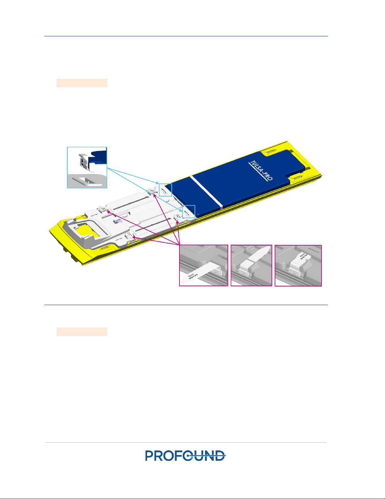
5.a.i Setting up the Base Plate, Patient Pad, and Straps
1. MRI Technologist: Attach the base plate onto the foot end of the MRI table and secure using
the four base plate straps (Figure 2, some configurations not exactly as shown). The feet of the
base plate should fit in the rails of the MRI table and not move around when in position.
2. Place the patient pad on the MRI table and secure it using the provided straps (Figure 2, some
configurations not exactly as shown). Drape the upper part of the patient pad with a sheet and
place an absorbent pad at the end closest to the base plate.
Figure 2. Securing the base plate and patient pad to the MRI bed.
5.a.ii Preparing a Work Surface and Connecting the Positioning System
1. MRI Technologist: Prepare a work surface on the countertop or cart in the MRI magnet room
for performing quality assurance checks on the Ultrasound Applicator (UA), the Endorectal
Cooling Device (ECD), and the Positioning System (PS).
2. Place the Positioning System and Positioning System Interface Box (PSIB) on the work surface.
Manually move the PS backward as far as possible using the adjustment release. Adjust the PS
manual vertical axis to near the top end of the range of travel, with the tilt angle horizontal or
slightly tilting down.
3. Connect the PS cable between the PS and the PSIB. Connect the large white cable from the
Filter Box (on the wall on the inside of the MRI magnet room) to the PSIB.

Equipment Setup
TULSA-PRO® Operator’s Manual
- GE MR750w 3T
111229B
Page 16 of 130
Be careful when installing the cable between the Filter Box and the PSIB. The cable
pins must be carefully mated to the receptacle connector and not forced into place.
Too much force will damage the cable pins.
5.b Preparing the System Cart Outside the MRI Magnet Room
MRI Technologist: The System Cart contains the fluid circuit hardware used to cool the Ultrasound
Applicator (UA) and the Endorectal Cooling Device (ECD). Here is how to prepare the System Cart:
5.b.i Cart Setup
1. To provide access for the fluid tubes, position the System Cart near a waveguide in the
equipment room. Ensure that airflow from the rear vent is not obstructed.
2. Lock the casters on the wheels to fix the System Cart in place.
3. While pressing the pole clamp release, raise the System Cart pole to its fully extended
position.
5.b.ii Fluid Preparation
The ECD fluid supplements are not safe for drinking and should not come into
skin contact. Use gloves when handling and do not ingest.
The fluid circuit tube sets have color-coded stickers and Luer fittings to distinguish them: red and
white for the UA circuit, blue and yellow for the ECD circuit.
Prepare two 1000mL IV bags of sterile water. One will be treated with fluid supplements and used
for the ECD fluid circuit, while the other will be used without supplements for the UA fluid circuit.

Equipment Setup
TULSA-PRO® Operator’s Manual
- GE MR750w 3T
111229B
Page 17 of 130
1. Designate one of the water-filled 1000mL IV bags as an ECD IV bag. Using a 30-60mL syringe
with a 16G needle, extract 5mL of ECD Fluid Supplement –Manganese Chloride. Inject this
solution into the syringe port of the ECD IV bag.
2. Withdraw 20mL of ECD Fluid Supplement –Span & Tween. Inject this solution into the
syringe port of the ECD IV bag.
NOTE: The additives Manganese Chloride and Span & Tween help to prevent
bubbles within the ECD and ECD fluid line. Do not refrigerate the sterile water or
the ECD additives; when cold, the additives do not mix well and take longer to
dissolve.
3. Shake the ECD IV bag for 30 seconds or until the solution is fully dissolved. The solution
should look milky white, which will help you distinguish the ECD IV bag from the UA IV bag.
4. Set aside the other 1000mL IV bag containing untreated sterile water. This will be the UA IV
bag.
Do not inject ECD fluid supplement into the UA fluid bag, because:
a. The ECD-fluid additives will eliminate the MRI signal shown from the water in
the UA acoustic window, which is important during the Alignment phase of
treatment planning. In other words, you might not properly identify the UA
acoustic window and could misalign the UA.
b. You increase the risk of infection if the treated fluid should leak out of the UA
and into the urethra.
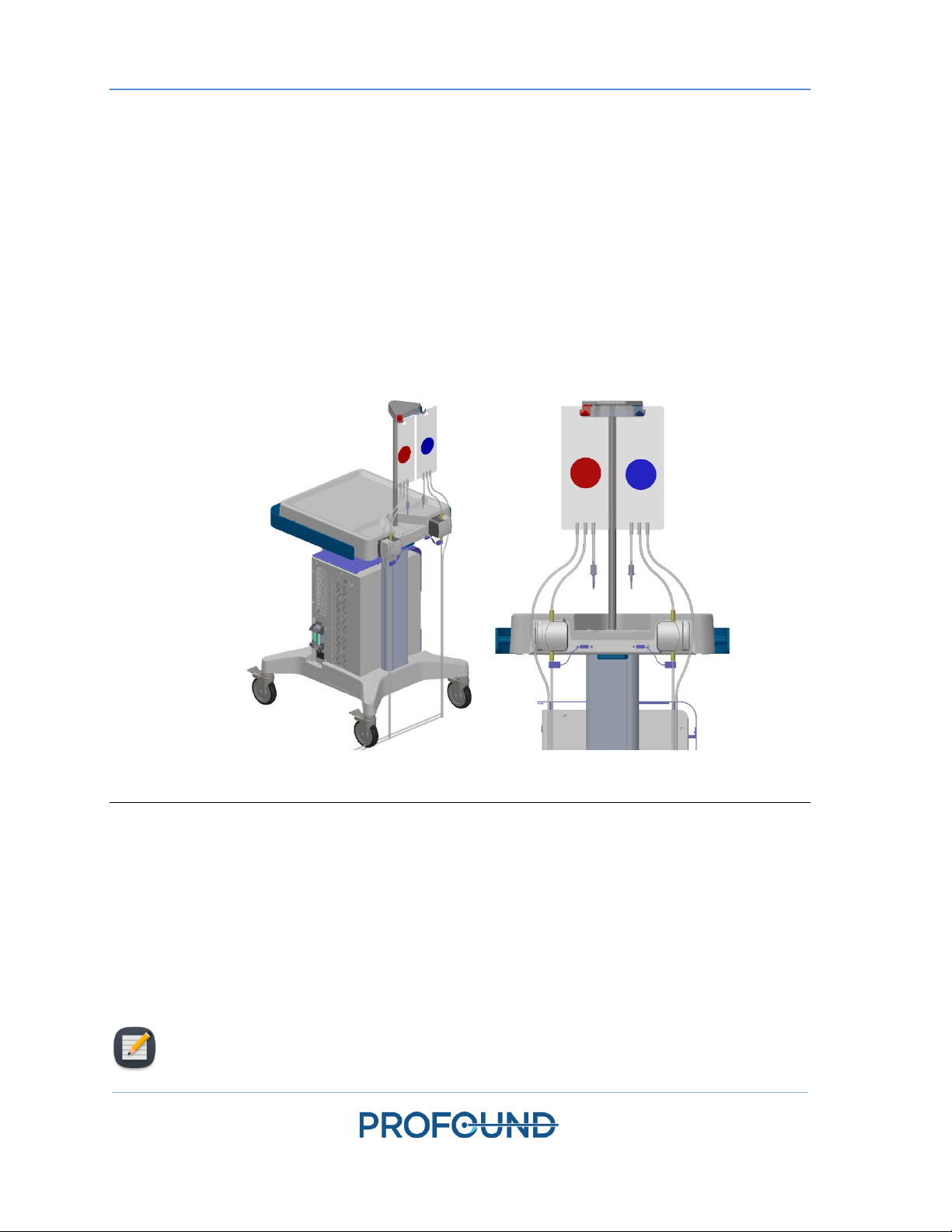
5.b.iii Tube Setup
1. Remove an ECD tube set (identified with a blue dot) from its packaging and install it on the
System Cart:
a. Lay the empty ECD reservoir bag on top of the Fluid Circuit tabletop.
NOTE: To avoid spills, ensure that the line clamps near the capped ends of
the tube set are closed.
b. Place the pump section of tube set into the ECD pump head and close it.
Avoid pinching the pump section of the tubing when installing it into the peristaltic
pump head. Pay attention to both the top and bottom (inlet and outlet) of the
pump head.
NOTE: If the tubing is pinched in the pump head, the tubing could fail in the
middle of a treatment and cause a large water leak.
c. Connect the ECD pressure sensor to the corresponding connection on the System
Cart.
Equipment Setup
TULSA-PRO® Operator’s Manual
- GE MR750w 3T
111229B
Page 18 of 130
d. Insert the spike from the empty bag into the treated ECD IV bag and then open the
line clamp by the spike port to allow the contents of the ECD IV bag to be
transferred to the ECD tube set.
e. When all the contents from the ECD IV bag have been transferred to ECD reservoir
bag, close the line clamp in between.
f. Hang the ECD reservoir bag on the blue weight sensor hook on the System Cart
(Figure 3).
2. Repeat Step 1 for the UA circuit using a UA tube set (identified with a red dot).
3. With assistance from someone inside the magnet room, pass the UA and ECD tube sets
(capped ends) through the appropriate waveguide, into the magnet room. Secure the tube
sets near the MRI work surface.
Figure 3. Preparing the system cart and fluid tube sets.
5.c Connecting the System Electronics
The System Electronics enclosure is typically located in the MRI equipment room on the System Cart
and close to the penetration panel holding the Filter Box. One large, black cable connects the Filter
Box to the System Electronics. The System Electronics, Filter Box, and cable are installed by
Profound Medical, and can remain connected when not in use.
To prepare the System Electronics for use, ensure the following connections are secure:
NOTE: If any cables are not connected, ensure they are free from damage before
connecting.

Equipment Setup
TULSA-PRO® Operator’s Manual
- GE MR750w 3T
111229B
Page 19 of 130
1. The cable from the fluid circuit electronics, located under the cart tabletop, to the System
Electronics enclosure.
2. The large black cable from the System Electronics enclosure to the Filter Box.
3. The Ethernet cable from the System Electronics enclosure to the Treatment Delivery
Console (TDC) computer.
4. The System Electronics enclosure to a mains power outlet using a grounded, medical-grade
power cord. Do not use extension cords.
NOTE: If you need to disconnect the SE power cord, it is a latching connector and
you must squeeze the two tabs together to remove the cord properly.
5. When all connections are established, turn on the power switch at the back of the System
Electronics enclosure.
5.d Register patient on the MRI console
1. Register a new patient on the MRI console from the Worklist Manager tab using the
information obtained at the time of admission. The patient orientation must be Head First –
Supine. When prompted, select Normal dB/dt and Normal SAR.
2. Load the TULSA-PRO MRI sequence protocol from the Protocol Library.
NOTE: The patient’s last name, first name, ID, date of birth, and physician name
registered on the MRI console will be used to populate the TULSA-PRO Treatment
Report.
5.e Preparing the Treatment Delivery Console (TDC)
5.e.i TDC Computer Setup
1. Ensure the TDC computer is placed in the control room close to the MRI console and is
connected to the System Electronics and the MRI Host via Ethernet cables.
2. Power on the TDC computer and monitor.
3. Log in to Windows on the TDC computer when it powers up. Profound Medical will provide
the username and password after system training has been completed.
NOTE: To check that the TDC computer is connected to the MRI, click on the
icon on the bottom right of the MRI console, and ensure that TULSAPRO is
selected.
5.e.ii Clock Synchronization
To correctly recognize and accept the most recent planning images, the clocks of the TDC computer
and MRI host computer must be synchronized. If the TDC computer time zone is different or the
TDC computer time is more than 1 minute ahead or behind the MRI host, follow these steps to
adjust the TDC system time:
Equipment Setup
TULSA-PRO® Operator’s Manual
- GE MR750w 3T
111229B
Page 20 of 130
1. On the TDC computer, right-click on the computer time in the bottom right of the screen,
and click Adjust date/time from the list.
2. In the Date & Time dialog, use the Time Zone drop-down list and Daylight Saving toggle
switch to select the same Time Zone settings as the MRI host.
3. In the Date & Time dialog, click Change to manually adjust the time to match the MRI host
to the nearest minute.
4. Close the Date & Time dialog.
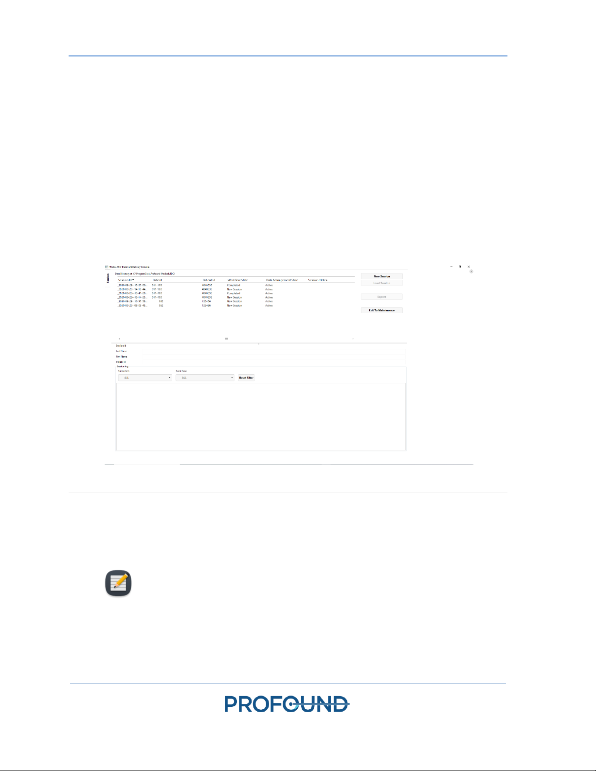
5.e.iii Treatment Delivery Console (TDC) Initialization
1. Launch the TDC software from the desktop. The Session Data Management workspace will
appear. Click New Session (Figure 4).
Figure 4: Session Data Management workspace of the TDC Main Menu
2. After selecting New Session, you will enter the Setup Workspace (Figure 5) where you can
ensure all equipment is functioning properly before proceeding.
A green checkmark will appear in the MRI quadrant of the Setup Workspace if the TDC
computer and MRI host can communicate with each other, and a patient is currently open
with the TULSA-PRO MRI sequence protocol on the MRI console.
NOTE: TDC automatically locks the session 12 hours after it was started and will not
allow further changes to the session.
Table of contents
Other Profound Medical Equipment manuals

Popular Medical Equipment manuals by other brands


Getinge
Getinge Arjohuntleigh Nimbus 3 Professional Instructions for use

Mettler Electronics
Mettler Electronics Sonicator 730 Maintenance manual

Pressalit Care
Pressalit Care R1100 Mounting instruction

Denas MS
Denas MS DENAS-T operating manual

bort medical
bort medical ActiveColor quick guide

AccuVein
AccuVein AV400 user manual


