Progres AGRONIC 2500 User manual

Sections in the manual:
‒ Functional description
‒ Features
‒ Formats, versions, models and options
‒ Technical specifications
‒ Parameters
‒ Input and output coding
‒ Practical examples
‒ Troubleshooting
‒ Technical support
The Communications Parameters section is detailed in
the Communications Manual.
The sections on Programming, Manual Actions and
Query are detailed in the User Manual.
INSTALLER USER MANUAL
AGRÓNIC 2500
Plus Version | V3
Welcome to the Agrónic 2500 manual.
We are pleased to count on your experience and skills to
install the Agrónic 2500.
This document will guide you through the process,
providing details on the programmer’s features and
parameters.
Your experience is essential to teach the customer how to
eectively use the Agrónic 2500.
Remember that there are two versions: basic and Plus,
adapted to the specific needs of each installation.
Thank you for your work!

Index
1 Description of basic functions............................................................................ 4
2 Features ............................................................................................................... 5
3 Formats, versions, models and options........................................................... 11
3.1. Formats.................................................................................................... 11
3.3. Versions.................................................................................................... 11
3.2. Models...................................................................................................... 11
3.4. Options..................................................................................................... 12
4 Technical specifications.................................................................................... 13
5 Parameters ........................................................................................................ 14
5.1. Fertilization.............................................................................................. 14
5.2. Filters........................................................................................................ 18
5.3. General..................................................................................................... 19
5.3.1 Diesel option................................................................................. 20
5.4. Programs.................................................................................................. 22
5.5. Sectors ..................................................................................................... 24
5.6. Determining factors................................................................................. 26
5.6.1 Definitive stop / Temporary stop................................................. 28
5.6.2 Conditional stop........................................................................... 29
5.6.3 Start – Start and Stop................................................................... 30
5.6.4 Warning......................................................................................... 31
5.6.5 Modify irrigation – Modify fertilizer ............................................. 32
5.6.6 End due to rain ............................................................................. 33
5.6.7 Filter pressure gage...................................................................... 34
5.6.8 Diesel pressure gage .................................................................... 35
5.6.9 Stop fertilizer................................................................................ 36
5.7. Sensors..................................................................................................... 37
5.7.1 Digital sensors .............................................................................. 37
5.7.2 Analog sensors ............................................................................. 38
5.7.3 Meter sensors ............................................................................... 40
5.8. Various ..................................................................................................... 41
5.9. Installer .................................................................................................... 42
5.8.1 Erased ........................................................................................... 42
5.8.2 Events ........................................................................................... 42
5.8.3 Access codes................................................................................. 42
5.8.4 Activate options ........................................................................... 42
5.8.5 Various ......................................................................................... 42
5.8.6 Communications.......................................................................... 43
5.8.7 Language ...................................................................................... 43
5.8.8 Update soware........................................................................... 43
5.8.9 Backup copy ................................................................................. 43
5.10. Solar irrigation......................................................................................... 44
6 Input and output coding................................................................................... 45
7 Practical examples............................................................................................ 47
8 Troubleshooting................................................................................................ 48
9 Technical support.............................................................................................. 49
10 Function screen................................................................................................. 52
11 Parameters screen............................................................................................. 53

4User Manual | Agrónic 2500
1 DESCRIPTION OF BASIC FUNCTIONS
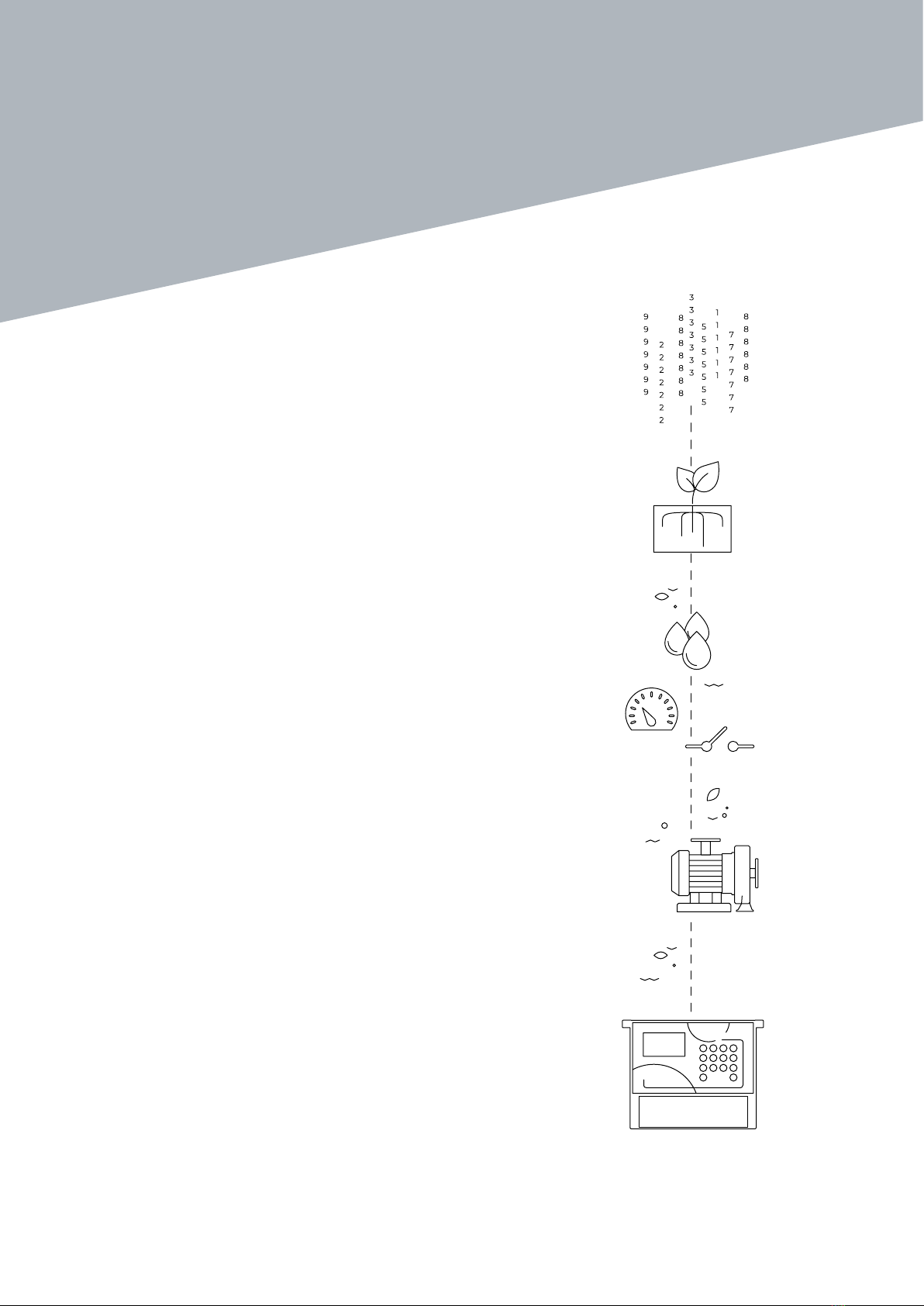
The Agrónic 2500 is designed for automating irrigation on small and medium-sized farms
(maximum 30 irrigation sectors) where there is a need to open/close sector and master valves,
fertilizer control and filters.
The farm may have a pressurized water intake or need
a drive pump (electric or motor pump). There may be
an irrigation water meter.
The head can have 12 Vdc power supply (with solar
panel and battery, or battery only) or at 220 Vac (mains
or generator set).
The valves can be 12 Vdc, 24 Vac or latch and can be
close to the head and controlled by microtube or cable,
or at distances of up to 2 km connected to AgroBee-L
radio modules.
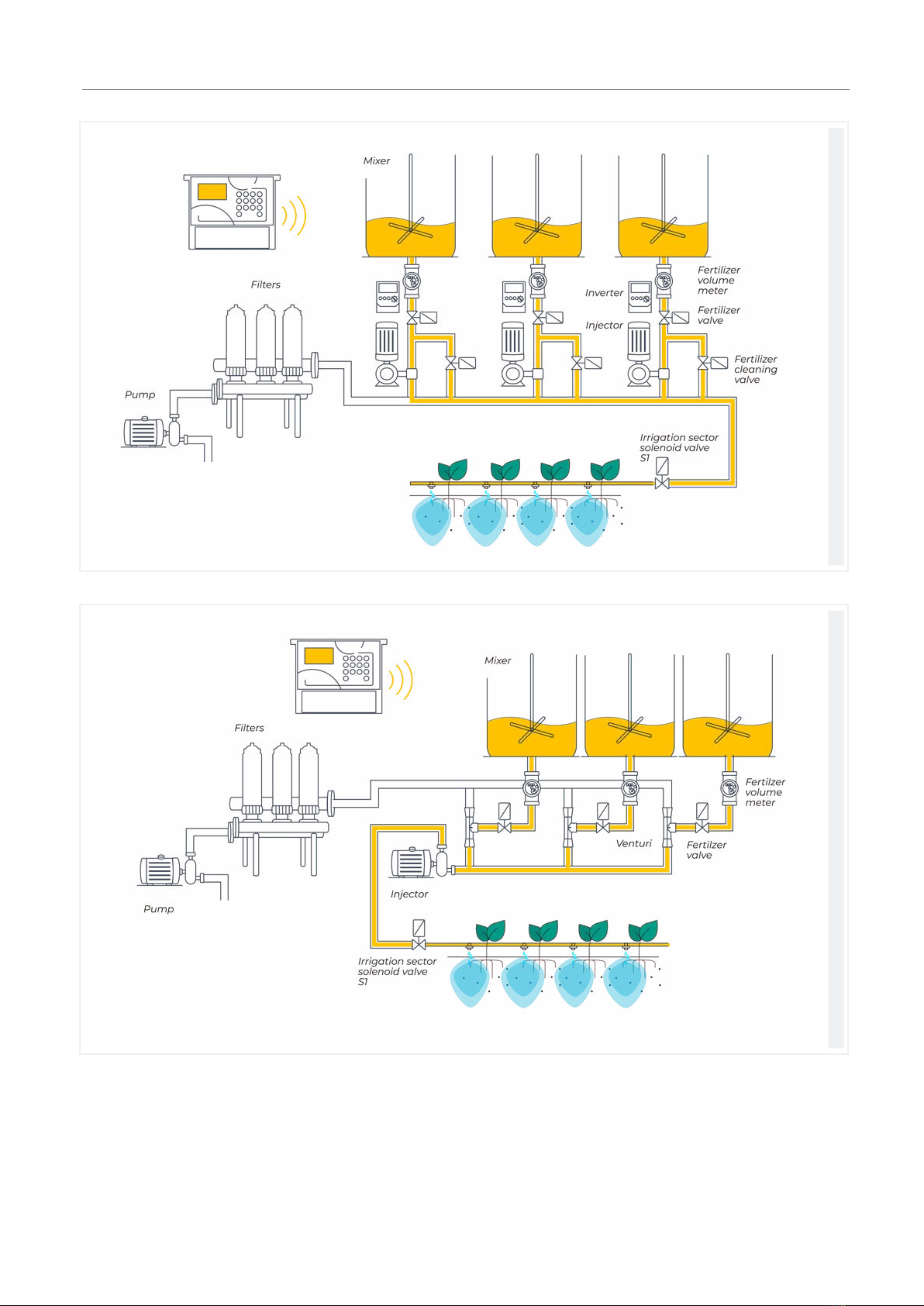
In the head, there can be fertilization with a hydraulic
pump injector, electric dosing machines or a venturis
system.
Reading of all types of sensors (analog, digital and
meters) connected to Agrónic and also remotely with
AgroBee-L radio modules.
The Agrónic 2500 has an internet connection, with
mobile telephony or WiFi, to connect to the VEGGA
platform or to the Agrónic APP application and
remotely manage the Agrónic.
For remote management, you can also connect to the
Agrónic PC Windows program. The connection can be
with direct USB to the computer, when it is next to the
unit, by radio modem, for medium distances, or by
Internet, with WiFi or mobile telephony.
All the features of the Agrónic are expanded in the
Plus version. If the Basic version does not meet your
requirements, see the Plus version.
To go from the Basic to the Plus version, just activate
an option from the unit.
5
User Manual | Agrónic 2500
Control up to 30 sectors using 50 irrigation programs.
Each program can activate 1 to 4 irrigation sectors si-
multaneously.
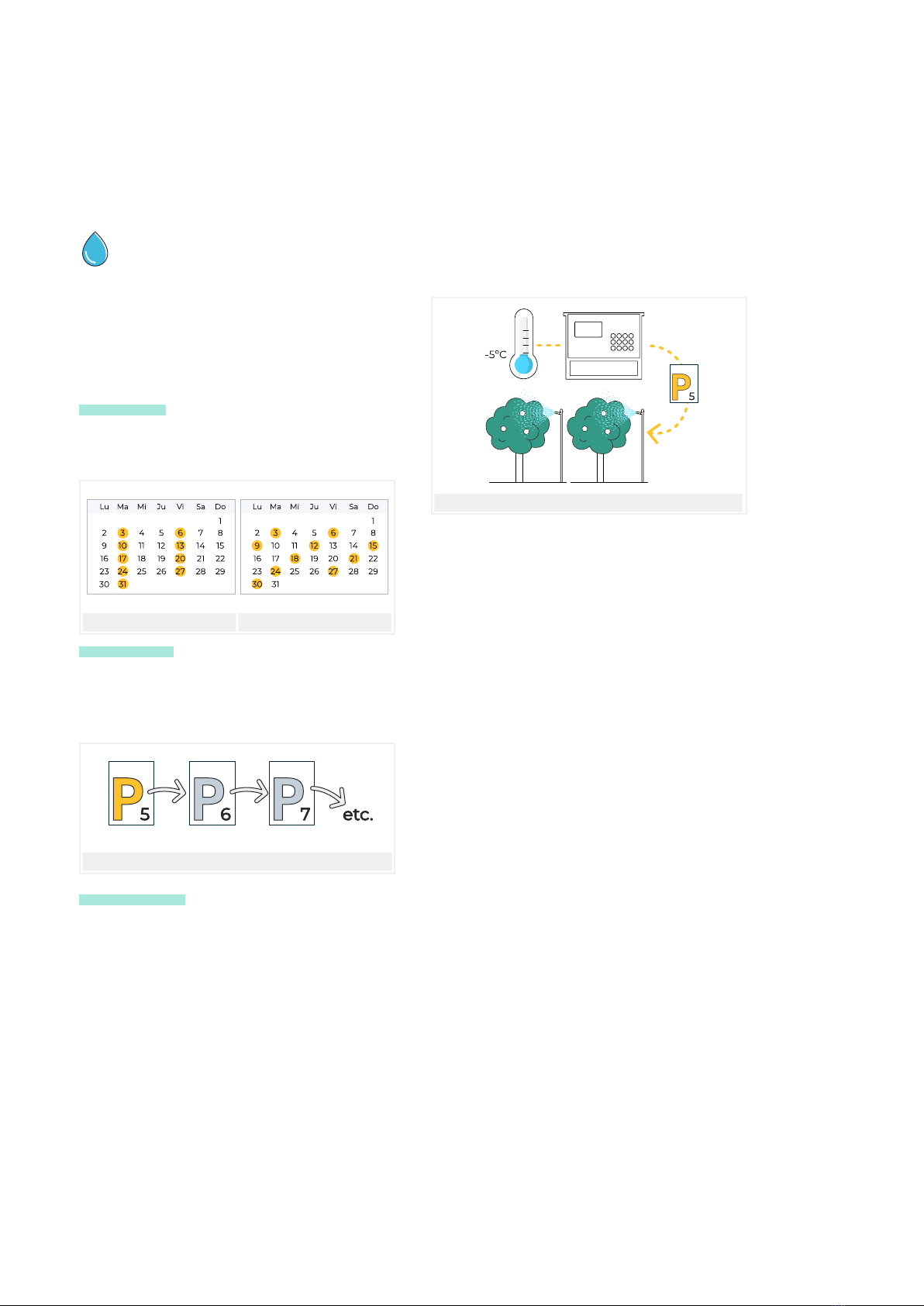
There are three ways to start a program:
Schedule start: at a specific time choosing the days
of the week or repeat the irrigation every few days
(frequency of days).
Days of the week Every 3 days
Sequential start: when another program has finished.
It is used to irrigate several sector groups one aer
another. The first program in the sequence must be
schedule start or conditional.
P6 sequential of P5 and P7 sequential of P6, etc.
Conditional start: when a determining factor is
activated.
The determining factor is related to any type of sensor
and can activate the program, for example, when
the temperature rises, when a buoy is deactivated
or when a flow rate drops below a certain level. An
active schedule and a safe schedule can be configured
between starts.
Conditional start due to frost
Once the program has started, there is an option to
repeat the irrigation every certain amount of time.
At the start, the amount of irrigation can be modified
using the determining factors. For example, increase
irrigation by % if there is a lot of radiation, decrease ir-
rigation by % if there is a lot of moisture in the soil, etc.
Irrigation units can be in time, hh:mm, mm:ss or
hh:mm/ha; or in volume, m3 or m3/ha (m3 per hectare).
A record is made of the irrigation time and volume for
each sector and in total.
When the program is active, irrigation can be stopped,
permanently or temporarily, using a determining
factor. For example, stopping when it is very windy,
stopping while the well level is low, stopping when the
flow in a sector is too high (broken pipe), etc.
2 FEATURES
The Agrónic 2500 is a controller for controlling irrigation, fertilization, pumping and filter cleaning.
It detects malfunctions and creates a chronological record of the events. Fully configurable, with
multiple possibilities for use, communication and expansion.
IRRIGATION
6User Manual | Agrónic 2500
Description of basic functions
PUMPING
It has 2 general irrigation outputs, or pumps.
One of the pumps can be a motor pump or generator
set. Each sector is assigned with the pumps associated
to it.
The pumps are activated together with the sector.
There are time delays to separate the pump from the
sector activation, during activation as well as stop, to
avoid water hammer.
Configurable from 0 to 4 fertilizers in separate tanks.
Separates pre- and post-irrigation values in each
program.
Fertilization units in time (hh:mm or mm:ss) or in
volume (L or L/ha).
Configured to use mixers, with pre-mixing and inter-
mittent or continuous mixing.
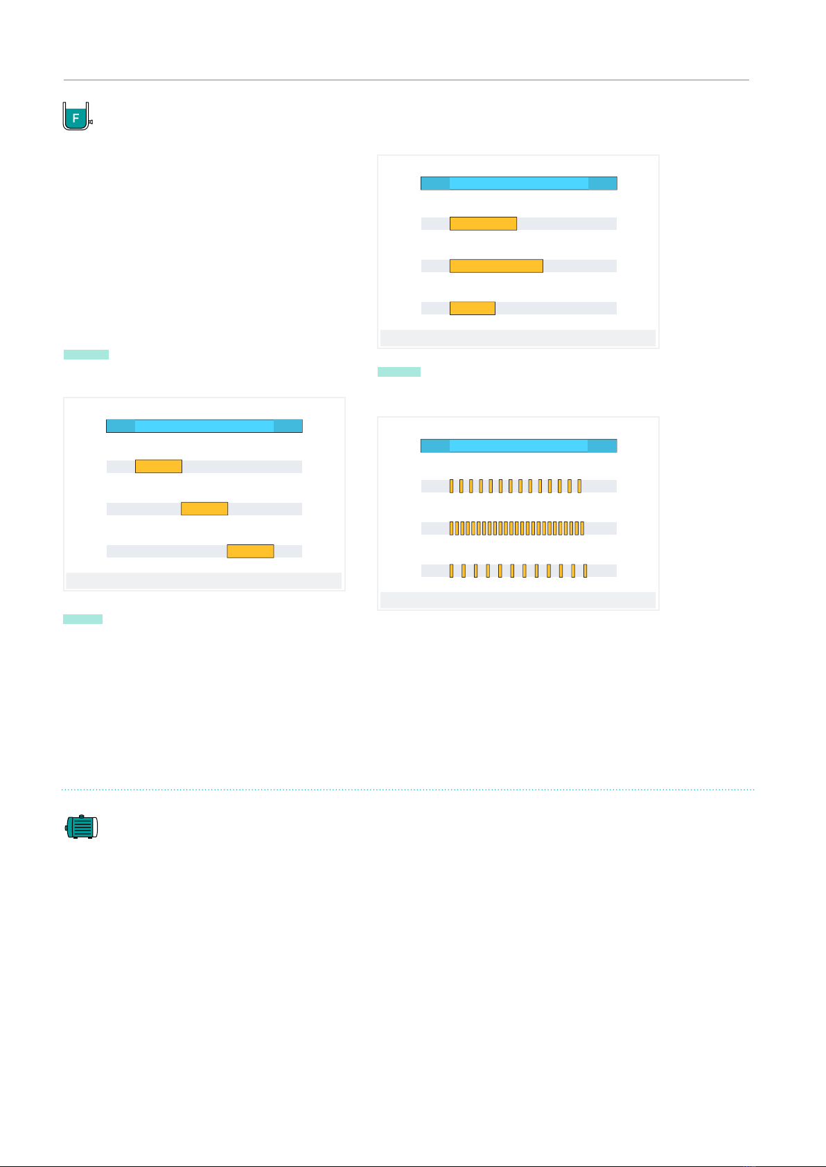
Fertilizers can be applied in three dierent ways:
in series: one type of fertilizer aer another from a
single injector
Series fertilization
IRRIGATION
FERTILIZER 1
20 L
30 L
12 L
FERTILIZER 2
FERTILIZER 3
Parallel: various fertilizers simultaneously with one
injector per type.
Parallel fertilization
FERTILIZER 1
IRRIGATION
FERTILIZER 2
FERTILIZER 3
20 L
30 L
12 L
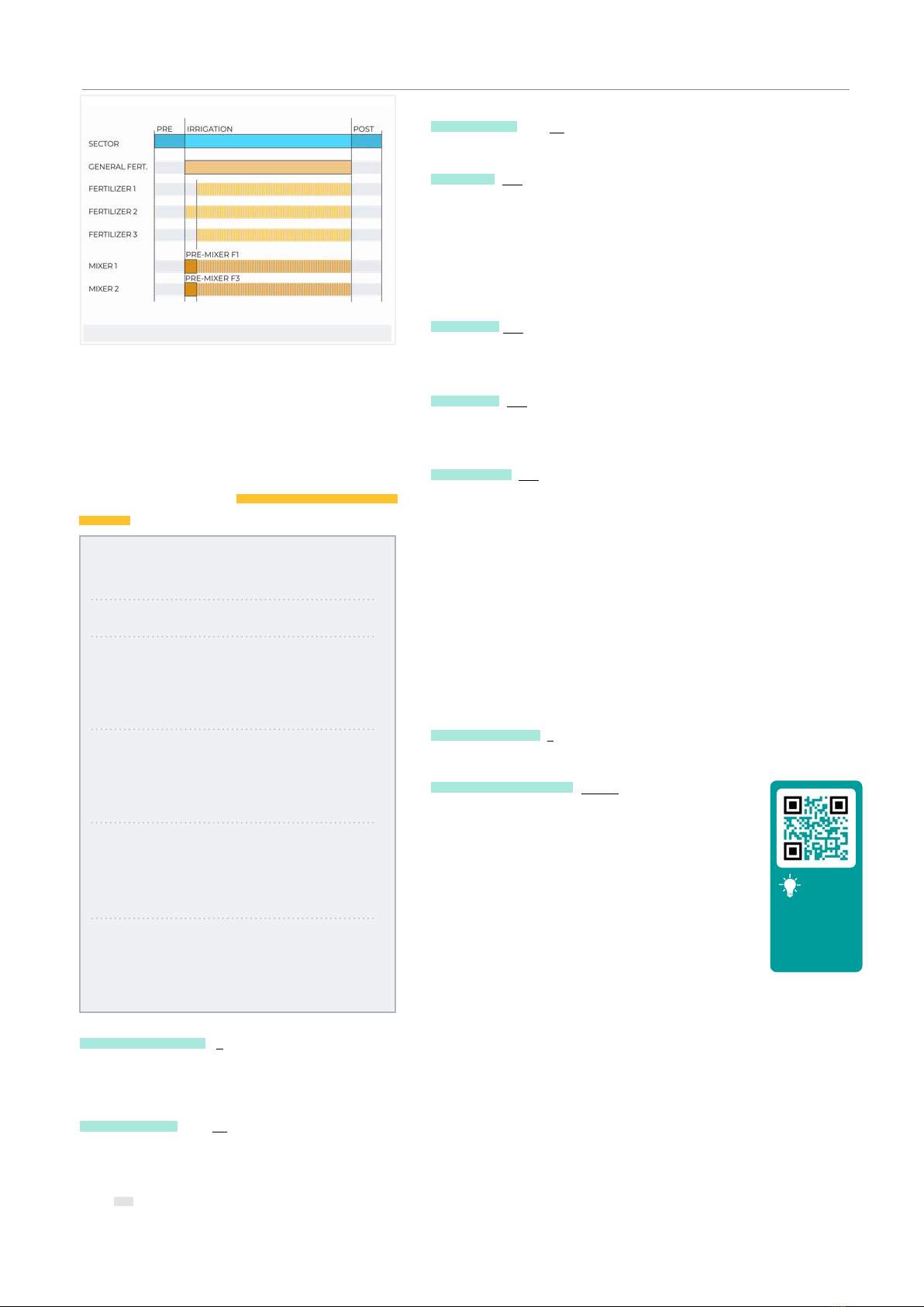
Uniform: applies and distributes the each type of fertil-
izer uniformly between pre- and post-irrigation.
Uniform fertilization
IRRIGATION
FERTILIZER 1
20 L
30 L
12 L
FERTILIZER 2
FERTILIZER 3
In volume fertilization, detect no pulses or leak. The
proportional distribution of each pulse made by the
meter is recorded into the totals and history according
to the planned flows in sectors being fertilized at the
same time. Parallel fertilization.
FERTILIZATION

7
Description of basic functions
User Manual | Agrónic 2500
FILTER CLEANING
Configured for 0 to 9 filters, with selectable cleaning
times. Programmable pause between filters.
Washing sequence may be started by the pressure dif-
ferential and/or according to the time or volume of the
water circulation.
Whether or not the irrigation sectors and fertilizers are
stopped while the filters are being cleaned is configu-
rable.
Control over malfunctions due to continuous cleanings.
Configurable general filter output.
DETERMINING FACTORS
The unit has a total or 30 completely configurable
determining factors to trigger actions that take into
account certain determining factors or values from
digital or analog sensors and meters.
There is a wide variety of actions possible, such as the
ability to make definitive, temporary or determined
stops that are applied to specific programs or all of
them, start and/or stop irrigation, send a warning,
adjust irrigation or fertilizer units when starting an ir-
rigation program according to an instantaneous value
from a sensor or the value recorded from a previous
irrigation, etc. Each determining factor can also be
configured to create a malfunction or send an SMS
message and an SMS message to another machine.
To give a few examples, it can be used to terminate ir-
rigation due to a broken pipe, postpone irrigation due
to the lack of water level or excessive wind, modify the
volume of each irrigation as to the value of the water
content in the soil or the solar radiation the plant
received since its previous irrigation or the evapotrans-
piration, terminate irrigation if a certain amount of
rain has fallen since the previous irrigation, or send a
warning to the owner for an attempted the, etc.
Information about
Digital sensors
Analog sensors
Meter sensors
Flow error
Communication
Programs
Types of determining factors.
Definitive stop
Temporary stop
Conditional stop
Start
Start / Stop
Warning
DETERMINING FACTORS
Modifying irrigation
Modifying fertilizer
End due to rain
Filter pressure gage
Diesel pressure gage
Stop fertilizer

8User Manual | Agrónic 2500
Description of basic functions
PIVOT CONTROL
Remote management of up to 4 circular and linear
pivots. Its features are:
• position reading by GPS.
• Speed and direction control.
• Deactivation of the jet and the wing according to
position.
• Control of diesel pumps or solar irrigation.
• Control of physical guards in sector pivots.
• Manual action such as start, stop, dry passes, etc.
• Sectorization and configuration of up to 8 irrigable
areas by pivot.
• Programming by time or by passes.
• Modify precipitation rate by area.
• Information on alarms, misalignment, slip and
pivot position.
Modify irrigation depending on the sensors (climate,
plant, soil).
Remote management through Agrónic APP, VEGGA
and Agrónic PC.
SOLAR IRRIGATION
Uses solar power to irrigate. It drives pumps using
solar panels connected to a solar radiation sensor and
a frequency drive.
It combines solar power and power from the electrical
grid or diesel pump in hybrid installations to ensure
irrigation on cloudy days or outside of sunlight hours.
Solar irrigation also allows irrigation at dierent
pressures, prioritizing sectors with higher pressure.
MANUAL
Through manual commands, the unit can:
• start, stop or place a program out of service
• Suspend a program for a few hours
• Leave the unit out of service or on general stop
• Start or stop filter cleaning
• Modify the time and date on the unit
• Terminate alarms and malfunctions
• Set the sectors to manual, stop or automatic
• Modify virtual sensors
• Activate outputs
• Erase totals
• Place the determining factors out of service

9
Description of basic functions
User Manual | Agrónic 2500
EXTERNAL MODULES
SDI12 UNITS
With the AgroBee-L Link option, the unit links with
AgroBee-L radio modules, expanding the possibilities
and the use of new features.
The dierent modules in the range activate valves and
other irrigation elements, as well as read digital and
analog sensors and meters.
The SDI-12 is a communications bus that enables
the units that use this bus to communicate with the
Agrónic. Currently, soil moisture sensors from the
The AgroBee-L radio modules work with LoRa radio
modulation, which operates in the free bands of 868
MHz / 433 MHz / 915 MHz, obtaining coverage radii of
up to 2500 m between two points (depending on the
orography).
Meter Group, AquaCheck and Decagon brands can be
connected.
READINGS
The unit stores all totals in memory that cannot be
erased and, optionally, the events history and records
with the anomalies of the previous days.
• General totals and totals by sector for irrigation
and fertilization units in time and volume starting
from an initial date.
• Anomalies with time and date of the incident and
related instructions.
• Detailed records of every event occurring in the
unit.
• Separate history per irrigation sector with the units
in time and the irrigation and fertilizer volumes
applied everyday.
• History of every analog sensor with average values,
with maximum and minimums in 10-minute
fractions.
• History of every meter sensor with the irrigation
or fertilization values plus leaks in 10-minute
fractions.

10 User Manual | Agrónic 2500
Description of basic functions
SUMMARY OF PLUS VERSION FEATURES
SUMMARY OF BASIC VERSION FEATURES
Head
Pumping
2 general pumps or valves, pump 1 can be a generator set or motor
pump
Solar pumping together with generator set or network
Filters 9 filters in a single group
Fertilization
4 fertilizers
Type: series or parallel (uniform or not)
Units: hh:mm, mm’ss’’, Liters, Liters/ha
Irrigation
Sectors 30
Maximum 27 in the base, the rest in AgroBee or AgroBee-L
Programs
50 programs
From 1 to 4 sectors per program
Start type: schedule, sequential and determining factor
Units: hh:mm, mm’ss’’, hh:mm/ha m3, m3/ha
5 determining factors
Solar irrigation 10 determining factors
Sensors
Digital
20 sensors
Start cleaning / Temporary malfunction / Definitive malfunction
Conditional stop / Program start / Alarm
Analog 40 sensors
Meters 10 sensors
Irrigation meter / Fertilizer meters 1 to 4
Determining factors 30 determining factors
Pivots
4 pivots
Areas (by pivot) 8 Irrigation areas
8 exterior areas (wing and/or jet)
External modules AgroBee 16 modules
AgroBee-L 20 modules
SDI-12 8 units
Davis station 1 Weather station
Head
Pumping 2 general pumps or valves, pump 1 can be a generator set or motor
pump
Filters 9 filters in a single group
Fertilization
4 fertilizers
Type: series or parallel
Units: hh:mm, Liters
Irrigation
Sectors 30
Maximum 27 in the base, the rest in AgroBee or AgroBee-L
Programs
50 programs
From 1 to 4 sectors per program
Start type: hourly, sequential and by input
Units: hh:mm, m3
Sensors (inputs)
Digital
6 sensors
Start cleaning / Temporary malfunction / Definitive malfunction
Conditional stop / Program start / Alarm
Meters 5 sensors
Irrigation meter / Fertilizer meters 1 to 4
External modules AgroBee-L 20 modules

11
User Manual | Agrónic 2500
3 FORMATS, VERSIONS, MODELS AND OPTIONS
Box format
Built-in format in Agrónic 2509 and 2518 (9 and 18
outputs)
Built-in format in Agrónic 2527 (27 outputs)
Formats
Basic version
Plus version For analog sensor management,
This version is required.
It is activated by code.
Versions Observations
The Agrónic 2500 has two formats:
• box format With plastic box and transparent door
to hang on the wall.
• Built-in format With metal box to be built-in on a
cabinet or desk.
The Agrónic 2500 has two versions, the Basic version
and the Plus version, which also has uniform fertil-
ization, more determining factors, analog sensors,
records, history, descriptive text in each element, more
than one irrigation meter, total per meter and, for ir-
rigation programs, operating by frequency of days, by
3.1. FORMATS
3.3. VERSIONS
Power
• Single 12 Vdc power supply model. It can be served
with an external power supply from 220 Vac to 12
Vdc (included with the 220/24 option).
Valve type:
• valves at 12 Vdc.
• Valves at 24 Vac. It can be served with an external
power supply from 220 Vac to 24 Vac (included with
the 220/24 option).
• Latch valves. Selectable 2- or 3-wire.
Number of outputs:
• models with 9, 18 and 27 outputs.
3.2. MODELS
Agrónic 2509 220/24 Vac Includes 220/12 Vdc 2 A power supply and 220/24 Vac 50 VA transformer
Agrónic 2509 12 Vdc
Agrónic 2509 latch 2-wire Includes solar regulator
Agrónic 2509 latch 3-wire Includes solar regulator and diode box
Agrónic 2509 12 Vdc dual voltage Includes 220/24 Vac 50 VA transformer and diesel pump control option
Agrónic 2509 12 Vdc with battery charger The Plus version and GPRS modem option are required
Agrónic 2518 220/24 Vac Includes 220/12 Vdc 2 A power supply and 220/24 Vac 50 VA transformer
Agrónic 2518 12 Vdc
Agrónic 2518 latch 2-wire Includes solar regulator
Agrónic 2518 latch 3-wire Includes solar regulator and diode box
Agrónic 2518 12 Vdc dual voltage Includes 220/24 V 50 VA transformer and diesel pump control option.
Agrónic 2518 12 Vdc with battery charger The Plus version and GPRS modem option are required
Agrónic 2527 220/24 Vac Includes 220/12 Vdc 2 A power supply and 220/24 Vac 50 VA transformer
Agrónic 2527 12 Vdc
Agrónic 2527 latch 2-wire Includes solar regulator
Agrónic 2527 latch 3-wire Includes solar regulator and diode box
Agrónic 2527 12 Vdc dual voltage Includes 220/24 Vac 50 VA transformer and diesel pump control option
Agrónic 2527 12 Vdc with battery charger The Plus version and GPRS modem option are required
9 Outputs18 Outputs
Models Observations
27 Outputs
activations, by schedule and active period.

12 User Manual | Agrónic 2500
Formats, versions, models and options | Options
3.4. OPTIONS
Remote management communicationRadio control
Sensor control
Cloud
“Web platform”
(Agrónic APP +
VEGGA)
License to connect the unit to the
cloud.
The GPRS or WiFi modem option are required.
To use the Agrónic APP or VEGGA, the unit must be registered in
the cloud and an annual fee paid.
It is activated by code.
Cloud + PC
“Agrónic PC
program”
(Agrónic PC +
Agrónic APP +
VEGGA)
GPRS and WiFi – License to connect up
to 3 PCs/Servers or to the cloud.
USB, RS485 and Radiolink – License to
connect 1 PC/Server.
The GPRS, WiFi, USB, RS485 or Radiolink modem option are
required.
To use the Agrónic APP or VEGGA, the unit must be registered in
the cloud and an annual fee paid.
It is activated by code.
Modem link / SMS
messages
Option to connect with Agrónic PC,
Agrónic APP and VEGGA via GPRS, and/
or receive SMS messages from the unit.
Includes GPRS modem with deactivated Movistar M2M SIM card.
Includes 5dBi quad-band antenna and 3 meters of cable.
Not compatible with the WiFi Link option.
WiFi link Option to connect with Agrónic PC,
Agrónic APP and VEGGA via WiFi router.
Not compatible with the GPRS Modem Link / SMS Messages
option.
Includes 7dBi directive antenna with six meters of cable and 3dBi
omni-directional antenna.
USB link Option to connect with Agrónic PC
via cable. Includes three meters of cable.
433 MHz radio link Option to connect with Agrónic PC
via radio.
An Agrónic Radiomodem 433 MHz must be connected to the PC
with the Agrónic PC program.
See Agrónic Radiomodem 433 MHz in the Accessories section.
RS 485 link for PC Serial port to connect with Agrónic PC
with RS485 Link box.
A 220/12 V 2 A power supply and an RS485 + USB link box are
required.
AgroBee-L Link
868 MHz / 915
MHz / 433MHz
Option to connect with external
AgroBee-L modules (Lora technology).
Only valid for units with version 3. Includes coordinator, omni-
directional antenna with 10 meters of cable, optionally 15 meters
of cable (check price). The Plus version must be activated in order
to activate general and read analog sensors.
AgroBee-L link
868 MHz / 915
MHz / 433MHz +
modem
Option to connect with external
AgroBee-L modules (Lora technology)
with GPRS modem included on the
same board.
Only valid for units with version 3. Includes deactivated
Movistar M2M SIM card and 5dBi quad-band antenna with 3
meters of cable for the GPRS modem. For the AgroBee-L modem,
coordinator, omni-directional antenna with 10 meters of cable,
optionally 15 meters of cable (check price). The Plus version must
be activated in order to activate general and read analog sensors.
RS 485 Modbus
link
Serial port to connect to Davis Vantage
Pro 2 weather station.
Only valid for units with version 3.
The “SDI-12 expansion and 4 analog inputs” option and the
“Gateway for Davis Vantage Pro” complement are required.
2 Analog inputs
Connector for 2 analog inputs.
For voltage and current measurement
(V/mA). The Plus version must be activated on the computer.
SDI-12 expansion
and 4 analog
inputs
Board to incorporate 8 sensors with
SDI-12 protocol + 4 analog 4-20 mA
sensors.
Only valid for units with version 3 and Plus version activated.
See Sensor section to see compatible SDI-12 models.
5 digital inputs Connector for 5 digital inputs. Only for relay models (not compatible with latch units).
Pivot control
Option to control position, movement
direction, speed, start, stop, etc. up to
a maximum of 4 pivots.
The Plus version must be activated on the computer.
It is activated by code.
Diesel pump
control
Option for automatic start of a motor
pump or generator set. It is activated by code.
Options Description Observations
Other
13
User Manual | Agrónic 2500
Voltage 12 Vdc +15% -10%
Frequency --
Power consumption Less than 12.5 W (0.3 W standby)
Fuse Input Thermal (PTC) 1.1 Amp. at 25°C, auto-resettable
General power supply
Voltage From 12 to 24 Vdc or Vac (maximum 30 V)
Fuse Input “R+” Thermal (PTC) 3.0 Amp. at 25°C, auto-resettable
Output power source
Memory No maintenance, 10 years for parameters and programs in FRAM memory and FLASH memory
records
Clock 48 hours without power
Memory and clock safeguard
Digital
Number 9, extendable to 18 and 27.
Type By relay contact, with 24 VAC potential (external transformer).
Limits 30 Vac / 30 Vdc, 1 Ampere, 50-60 Hz, CAT ll (per output)
All outputs have double isolation in respect to the power output.
Outputs
Temperature -5°C to 45°C
Humidity < 85%
Altitude 2000 m
Pollution Grade 2
Environment
Box model From 1.0 kg to 1.6 kg
Built-in model From 1.1 kg to 1.5 kg
Weight
This symbol indicates that electronic devices should not be disposed of along with household waste at the end of their
useful life. The product must be taken to the corresponding collection point for electric and electronic unit recycling and
correctly processed pursuant to Spanish legislation.
Digital sensors Number 6, expandable (option) to 11 on non-Latch models.
Type Coupling options, operate at 12 or 24 V
Analog
(option)
Number 2
Type 4-20 mA, 0-20 V. (on demand, with galvanized separation)
Number 4
Type 4-20 mA
Inputs
Complies with Directive 89/336/EEC for Electromagnetic Compatibility and Low Voltage Directive
73/23/EEC for Product Safety Compliance. Compliance with the following specifications was
demonstrated as indicated in the European Community Oicial Gazette.
Statement of compliance
4 TECHNICAL SPECIFICATIONS
Protective ground
terminal Antenna Ground terminal Double isolation
Symbols that may appear on the product

14 User Manual | Agrónic 2500
5.1. FERTILIZATION
5 PARAMETERS
To access the menu, press ‘Function’ on the keypad,
select 4. Parameters, ‘Enter’.
FUNCTION
1. PROGRAMS
2. MANUAL
3. READINGS
4. PARAMETERS
5. PIVOTS
It is divided into twelve sections. To enter one of them,
just press the corresponding index number or move to
the selection with the arrow keys and then press ‘Enter’.
PARAMETERS
1. Fertilization
2. Filters
3. General
4. Programs
5. Sectors
6. Communications
7. Determining factors
8. Sensors
9. Various
10. Installer
11. Solar irrigation
12. Pivot
If a menu has more than 5 lines, the ‘↓’ symbol will be
displayed to indicate that they do not fit on the screen, so
press the index number or move the ‘↓’ key to access them.
An example of how to interpret the questions and how
to modify the possible values to configure is explained:
Example
Type of fert. (series | parallel) YES FRI
• Indicates that there are several options to
modify.
N. of fertilizers (0 ... 4)
• Underlined value or number: indicates the
default value that is configured in the con-
troller.
Fertilizer general (yes | no) YES
• Indicates the option to respond with ‘yes’ or
‘no’.
Example of interpretation
N. of fertilizers: 0
Fertilizer general: no
Type of fert.: series
The Agrónic 2500 can work up to four fertilizers.
The Plus version has three types of application: series,
parallel and parallel with uniform distribution.
Series fertilization
(one behind the other)
To install and prepare the unit for operation, enter the ‘Parameters’ section and adapt them to
the needs of each installation.
Parallel fertilization
(all at the same time)
Video tutorial
available for
this section
An example of how to interpret the questions and how
to modify the possible values to configure is explained:
Watch video
15
Parameters | Fertilization
User Manual | Agrónic 2500
Parallel fertilization uniform distribution
It works in units of time or volume and has an indepen-
dent pre/post irrigation for each program.
For each fertilizer, there may be a mixer that stirs the
fertilizer tanks before and during irrigation.
The outputs where the fertilization elements can be
connected are assigned in ‘Function - 4. Parameters - 3.
Generals’.
FERTILIZATION PARAMETERS
No. fertilizers: 4
General fertilizer: yes
F1 mixer: no
F2 mixer: yes
F3 mixer: yes
F4 mixer: no
Pre-mixing: 015”
Mixing start: 030”
Mixing stop: 120 ”
End cleaning: 030”
F1 Meter: 01
F2 Meter: 02
F3 Meter: 03
F4 Meter: 04
Flow rate F1: 000.00 m3/h
Flow rate F2: 000.00 m3/h
Flow rate F3: 000.00 m3/h
Flow rate F4: 000.00 m3/h
Number of fertilizers (0 ... 4): enter in the unit the
number of fertilizers installed in the irrigation network.
Leave the value at 0 if there are none.
Fertilizer general (yes | no): is an output normally used
to connect the injector in series application and is only
activated when one of the fertilizers activates.
Enter yes if it is going to be used.
Fertilizer mixer (yes | no): each fertilizer can be assigned
a separate mixer. Indicate which fertilizers have a mixer.
Pre-mixing (000 ... 999”): time that the fertilizer will be
stirred before starting fertilization. Pre-mixing comes
in before the program starts. If it is less than 10 minutes
since the last irrigation, do not start the pre-mixing.
Mixing during fertilization can be continuous or with
pauses.
Mixing start(000 ... 999”): mixing time before a pause. If
continuous mixing is desired, set the mixing pause to 0
and any time here.
Mixing stop (000 ... 999”): time that the mixing will be
stopped aer a startning time. If continuous mixing is
desired, set this time to 0.
Final cleaning (000 ... 999”): when fertilization ends, the
general and fertilizer cleaning outputs are activated
during this time. If the fertilization is in series, it cleans
at the termination of each fertilizer. If it is in parallel,
when the last one ends.
Fertilizer meters
If fertilizer by volume, the meters must be assigned.
When fertilizer is parallel or uniform, a meter must be
assigned to each fertilizer; if it is series, the same meter
can be assigned to all fertilizers.
Meter F1, F2, F3, F4 (0 ... 10): meter sensor number asso-
ciated with the fertilizer.
Flow rate F1, F2, F3, F4 (000.00 ... 655.35): maximum
planned injection flow rate for these fertilizers. The
planned flow rate is used for uniform fertilization.
Uniform fertilization
With uniform fertilization, the fertilizer is distributed,
injecting small doses, throughout the irrigation. This
achieves better nutrient absorption, more homoge-
neous growth, drainage losses and sedimentation in
pipes.
It is applied using simple Venturi-type hydraulic
systems, reducing installation costs and can be done
in time and volume.
See further
information
about uniform
fertilization
See
instruction

16 User Manual | Agrónic 2500
Parameters | Fertilization
Series fertilizationParallel fertilization
17
Parameters | Fertilization
User Manual | Agrónic 2500
Uniform fertilizationUniform fertilization with Venturis

18 User Manual | Agrónic 2500
Parameters | Filters
The Agrónic can control the filter cleaning. Cleaning
can be started manually or automatically. It starts au-
tomatically by a dierential pressure gage or by a time
or volume of water having passed through the filters. It
will only start automatically if the general one assigned
to the filters is activated. In other words, when there
is a program irrigating. It can be started manually
whenever desired from ‘Function - 2. Manual - 4. Filters’.
FILTER PARAMETERS
No. of filters 3
Initial wait: 000”
Time of activation
by filter: 045”
Pause between filters: 04”
Units between cleanings
Volume: 0000 m3
Time: 0000 ‘
General of filters: no
Relation with P1: yes
Relation with P2: no
Max. number of continuous
cleanings: 0
Stop of sectors: no
Number of filters (0 ... 9): number of filters.
Initial wait (000 ... 999”): the waiting time between ac-
tivating the filter general and starting cleaning the first
filter.
Activation time per filter (000 ... 999”): time that the
water will pass through each filter to perform cleaning.
Pause between filters (00 ... 99”): waiting time between
closing the cleaning of one filter and activating the
next one.
5.2. FILTERS
Units between cleanings (0000 ... 9999): the irrigation
time or volume that must pass through the filters for
automatic cleaning to begin. Time in minutes and
volume in m3.
Filter general (yes | no): indicate ‘yes’ to activate an
output during the entire filter washing process.
Relation with P1, P2 (yes | no): it indicates the pump
from which the water that passes through the filters
comes from. It is used to count units between cleanings
and to start the cleaning.
Maximum number of consecutive cleanings (0 ... 9): if
cleaning is started by the dierential pressure gage
and is always activated, it will do the cleanings config-
ured here at most. It then goes into malfunction and
will not continue cleanings until it is manually recon-
figured. At 0, it never goes into malfunction. To restart
cleaning go to ‘Function - 2. Manual - 4. Filters’.
Stop sectors (yes | no): if cleaning takes place during
irrigation, select whether or not to postpone the irri-
gation while it does so. It is used when sectors must be
closed during cleaning to maintain pressure.
• Yes: programs that have sectors related to the
pump that use cleaning are postponed. When the
cleaning is finished, the programs continue where
they were.
• No: the programs remain active during cleaning
and the irrigation sectors are not closed.
Video tutorial
available for
this section
Watch video
19
Parameters | General
User Manual | Agrónic 2500
5.3. GENERAL
The pump, fertilizers, filter and diesel outputs are con-
figured in this section.
The outputs can be from the base of the Agrónic 2500, a
recommended option and from external modules such
as the AgroBee-L, an option not recommended due to
the activation and deactivation delays they may have.
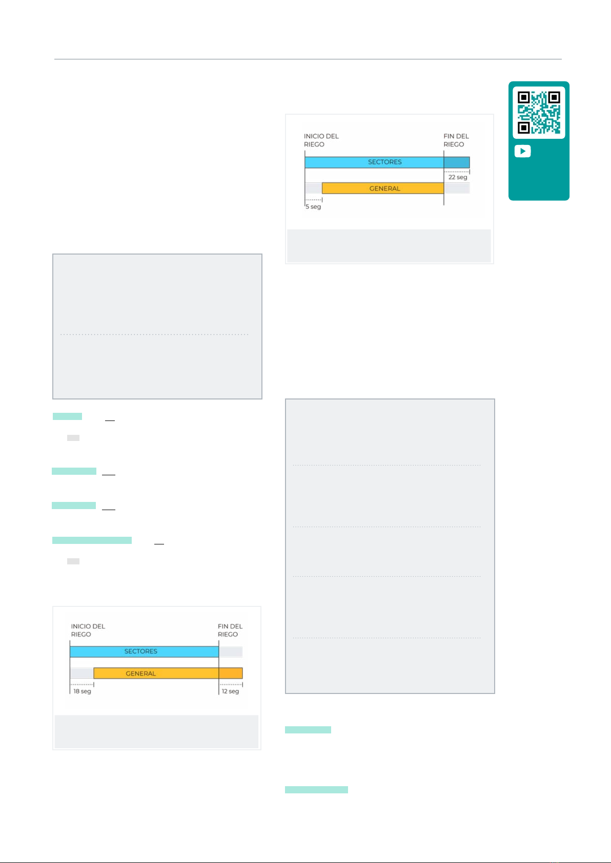
Pumps
Output connected to the drive pumps or general valves.
GENERAL PARAMETERS
Pump 1: yes
Temp. start: 018”
Temp. stop: 012”
Stopping the sectors: no
Pump 2: yes
Temp. start: 005”
Temp. stop: 022”
Stopping sectors: yes
Pump 1 (yes | no):
• Yes: i f pump 1 output is to be used. An output must
be assigned to the pump.
Temp. start (000 ... 250”): time delay in activating the
pump when starting an irrigation.
Temp. stop (000 ... 250”): time that the pump stop is
extended when stopping irrigation.
Stopping the sectors (yes | no):
• Yes: for the pump to stop when irrigation is finished
and for the sectors to remain open for a few more
seconds.
Start timing: 018
Stop timing: 012
Stop in the sectors: no
Start timing: 005
Stop timing: 022
Stop in sectors: yes
Outputs
At the base of the Agrónic 2500, there can be up to 27
digital outputs, identified as R1 to R27, to connect the
general outputs. It is recommended to start with the
unit’s last outputs and reserve the first ones for the
sectors.
GENERAL PARAMETERS
Assign outputs:
Pump 1: 00018
Pump 2: 00017
F1: 00015
F2: 00014
F3: 00013
F4: 00012
Fertilizer:
Pump: 00016
Cleaning: 00020
A1: 00000
A2: 00011
A3: 00000
A4: 00000
L1: 00010
L3: 00007
GL: 00000
Pumps
P1 and P2 : outputs connected to pumps or general
valves.
Fertilizers
F1, F2, F3, F4 : outputs connected to the fertilizer
injectors.
Video tutorial
available for
this section
Watch video

20 User Manual | Agrónic 2500
Parameters | Filters
MF: output connected to the pump or general fertilizer.
A1, A2, A3, A4: outputs connected to the mixers.
LF: output connected to the fertilizer cleaning valve.
Filter cleaning.
Before assigning the outputs, configure how many
filters there are in the installation. This is assigned in
‘Function - 4. Parameters - 2. Filters’.
L1: output assigned to the first filter.
Lx: output assigned to the last filter.
GL: output connected to the general filter cleaning
valve.
The outputs that occupy the filters between the first
and last are assigned automatically. If there is only one
filter, the last one is not asked.
Example
An installation with 4 filters, in which the assigned
outputs would be: l1 output 10, L2 output 9, L3
output 8 and L4 output 7.
The output number coding can be found in section ‘6
Input and output coding’ of this manual.
5.3.1 Diesel option
This option is used to start, stop and monitor diesel
pumps for malfunctions.
Operation
The diesel pump is related to pump 1. It starts when a
sector that uses pump 1 opens and stops when the last
sector that uses pump 1 closes.
First the sector is opened, the contact and preheating
output of the diesel pump is activated. When preheat-
ing is finished, the start output activates. If the pressure
gage input is activated, the diesel pump has already
started and irrigation begins. If it is not activated aer
the boot time, wait 30” and attempt another boot. If
the diesel pump cannot be started in 4 attempts, the
stop output is activated, it enters ‘Malfunction’ and
makes a record. The pump will attempt to start again
at the next irrigation start.
When irrigation is finished, it closes the sectors and
the pump, carrying out the water hammer timings and
once the end of pump time has transpired, it activates
the stop.
‘Consult - 1. General’ shows the status of the diesel
pump.
These screens only appear if the Diesel Option is
activated.
Pressure gage
A pressure gage is used to detect that the pump is
startning. Its purpose is twofold: to detect start-up
when attempting to start and, once finished, to detect
insuicient oil pressure. In the Agrónic Basic version,
the pressure gage must be connected to digital input 6
(D6). This input cannot be used for any other function.
If you have a generator on which there is no need to
control the pressure gage input, set the start and stop
times to 0.
GENERAL PARAMETERS
Preheating: 08”
Start-up: 04”
Stop: 060”
Pump input: 085”
Pump end: 0120”
Assign outputs:
ar Pa Co Pr
18 17 16 15
Preheating (00 ... 99”): time that the preheating output
(Pr) is activated before starting the diesel pump.
Start (00 ... 99”): time that the start output (Ar) is
activated to start the diesel pump.
Other manuals for AGRONIC 2500
3
Table of contents
Other Progres Farm Equipment manuals


Popular Farm Equipment manuals by other brands

Monosem
Monosem MECA V4 Assembly, Adjustment and Maintenance Instructions

sitrex
sitrex BR 2030/6 Operator's manual

Clarke
Clarke STRONG-ARM CST6 Assembly & user instructions

Alice's Garden
Alice's Garden CHABO CKC912BN manual

Land Pride
Land Pride CB1072 Operator's manual

Raven
Raven AutoBoom installation manual


