System Equine TRC-6 User manual

System Equine
14321 Fifth Line Nassagaweya • Rockwood, ON • N0B 2K0
1 (800) 461-3362 • Sales@SystemEquine.com
SystemEquine.com

ID PART # DESCRIPTION QTY 6’ QTY 8’
1 TRC8-1 Tine Assembly with Points (6.5”) 10 12
2 TRC-HB Adjuster Bar 1 1
3 TRC-SB Straight Bar 1 1
4 TRC-SBB S-Bar 2 2
5 TRC-BP Blade Post 1 1
6 TRC-AF A-Frame 1 1
7 Assembly Manual 1 1
8 TRC-TB5 Tine Bar 5’ 1 1
8.1 TRC-TB7 Tine Bar 7’
9 TRCBLADE6 Blade 6’ 1 1
9.1 TRCBLADE8 Blade 8’
ID PART # DESCRIPTION QTY 6’ QTY 8’
A TRC-P3/4 3/4”x 4 1/4”Hitch Pin for Blade Angle Adjustment 2 2
B TRC-P3/4 3/4”x 4 1/4”Hitch Pin for 3 Point Hitch 1 1
C TRC LIFT PIN Lift Arm Pin Cat I 7/8”x 5 1/2” 2 2
D TRC-P1/2 Pin 1/2 with Clip 1 1
E 02-2137 Hex Bolt 1/2”x 4”Hot Dipped Galv G5 with Lock... 1 1
F 02-2125 Hex Bolt 1/2”x 1 1/2”Hot Dipped Galv G5 with... 2 2
G TRC-S1 Spacer 1” 2 2
H 02-2157 Hex Bolt 3/4”4 1/2”Hot Dipped Galv G5 1 1
I 02-2158 Hex Bolt 3/4”x 5”Zinc G5 with Lock Nut 1 1
J 02-2111 Hex Bolt 3/8”x 1 1/2”Hot Dipped Galv G5 with... 10 12
K 02-2147 Hex Bolt 5/8”2”Zinc G5 with Lock Nut 3 3
L TRCTINE Tine Brackets 10 12

BLADE POST & BLADE
A-frame
STEP 2
Blade
Blade
Post
Blade
Post
Guides
TRACK & RING CONDITIONER ASSEMBLY INSTRUCTIONS
TRACK & RING CONDITIONER ASSEMBLY INSTRUCTIONS FOR MODELS: TRC-6 / TRC-8 / TRC-PULL-BEHIND-6 & 8
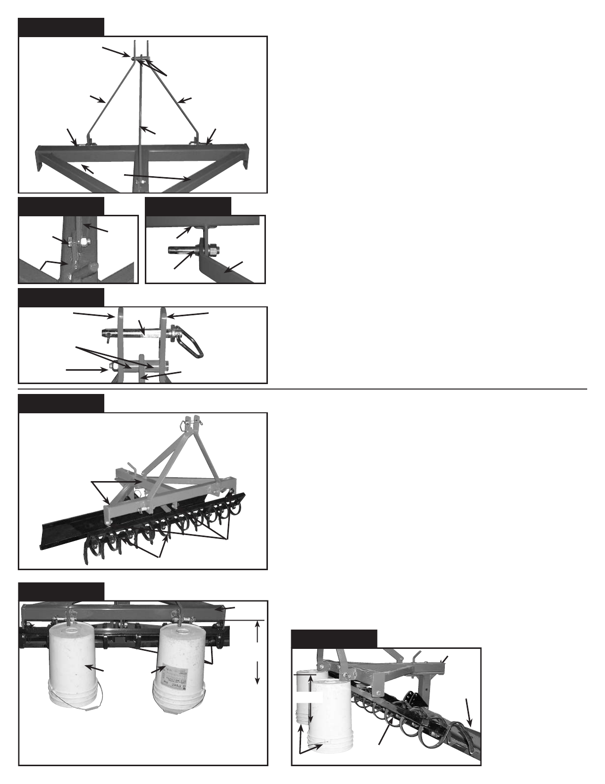
STEP 1
INSTALLING TINES ON TINE BAR
See fig. STEP 1 photo before proceeding.
1. Place tine bar between two supports as shown in STEP 1 photo (we used
the top and bottom of the shipping boxes anything that will give you at least
8” clearance will do.)
2. Place first tine on tine bar as shown in FIG 1A & FIG 1B. Attach and tighten
using 3/8” x 1 1/2” bolts and lock nuts. Repeat process until all tines are in
place.
NOTE: Tines should be spaced approximately 6” apart on center for the TRC-6
and 7” for a TRC-8.
THIS FINISHED SECTION WILL BE CALLED THE TINE BAR ASSEMBLY.
STEP 2
ATTACHING THE BLADE POST AND BLADE TO THE A-FRAME
See STEP 2 photo before proceeding
1. Position the blade post in the guides on the rear of the A-frame with blade
angle adjustment holes facing towards the front of the A-frame as shown
FIG 2A.
2. Using a 3/4” x 4 1/2” bolt put flat washer on bolt and put bolt through A-
Frame hole sliding into top of centre Blade Post hole. Tighten using 1 1/8”
wrench or ratchet & socket. NOTE: There is a nut is welded on to bottom
side of Blade Post Plate. (Make sure that the front hitch pin is in front hole
so Blade Post does not turn.)
3. Tighten the bolt and nut completely and then back off 1/4 turn to allow for
movement of the blade post.
4. Then drop in the 3/4” drop pin through the A-frame into a blade post adjust-
ment hole. Next position the blade face down and lift the blade post and
A-frame placing it into the slot on the back of the blade, and attach using the
3/4” x 5” bolt and lock nut FIG 2B. Again tighten completely and back off 1/4
turn to allow for movement. NOTE: leave blade assembly unfinished at this
time this will make the unit more stable for the rest of the assembly.
Tine
Clamp
FIG 1A
Tine
Clamp Bolt
FIG 1B
Box top & bottom used as supports
TINE BAR ASSEMBLY
Tine bar assembly mounting brackets
Tines at spaced at 6” for TRC-6 or 7” for TRC-8
Tine Bar
STEP 1
Blade post guides
FIG 2A
Blade
FIG 2B

STEP 3
ATTACHING THE 3 POINT HITCH
See STEP 3 photo before proceeding
1. First fasten the straight bar to the A-frame with a 1/2"x 1 1/2" bolt & lock
nut FIG 3A.
2. Then locate and fasten the two S-shape hitch bars to the A-frame with
the lift pins as shown FIG 3B.
3. Now take the unfastened ends of the S-shaped bar and straight bar and
using the 1/2” X 4” bolt & nut with the 1" spacers on either side of the
straight bar join the 3 ends as shown in FIG 3C.
4. Tighten these bolts now before proceeding.
5. Then install the hitch pin and fasten with the cotter pin.
NOTE: There will be approximately 1/4” of play around the hitch pin this
is normal.
STEP 4
ATTACHING THE TINE BAR ASSEMBLY TO THE A-FRAME
See STEP 4 photo before proceeding
1. Support the front of the A-frame at an approximate height of 14” to
16” (we used two 5 gallon buckets) place the buckets or whatever you
choose under the 3 point hitch brackets at the front of the A-frame FIG
4A.
NOTE: Keep supports clear of A-frame. IMPORTANT: make sure A-frame is
supported securely.
2. Now slide the tine bar assembly into position under the A-frame with the
tines pointing down and towards the blade at the back. FIG 4B
3. With help attach the tine bar assembly with the 5/8” x 2” bolts & lock
nuts to the 3 mounting brackets on the under side of the A-frame.
4. Tighten the bolts and back off 1/4 turn to allow tine bar assembly to
move freeely.
3 POINT HITCH ASSEMBLY
1” spacers
1/2” x 4” bolt and nut
A-frame
Straight
bar
S-shaped bar
Lift pinLift pin
S-shaped bar
STEP 3
1” spacers
Straight bar
Hitch pin
1/2” x 4”
bolt and nut
S-shaped bar
S-shaped bar
FIG 3C
A-frame
FIG 3A
Lift pin
FIG 3B
TINE BAR TO A-FRAME
A-frame
Tine bar
Assembly
brackets
Tine bar Assembly
STEP 4
A-frame
FIG 4A
14”
16”
A-frame
FIG 4B
Tine Bar
Assembly
Blade
14”-16”
5 gal.buckets
Tine Bar
Assembly
connection
points
NOTE: Tine bar needs to swing freely from A-frame connection points.
Tighten the bolts and back off each bolt 1/4 turn or until tine bar
assembly moves freely.
5 gal.buckets
1/2” x 1
1/2” bolt
and nut Straight
bar A-frame
S-Shaped
bar

STEP 5
ATTACHING THE TINE HEIGHT ADJUSTMENT BAR
See STEP 5 photo before proceeding
1. Locate the tine height adjustment bar and fasten to the center support
of the tine bar assembly using the 1/2” x 1 1/2” bolt & lock nut STEP 5
photo.
2. Lift and attach the other end to the center hole of the tine height adjust-
ment bracket attached to the under side of the A-frame using one of the
5/8” x 4 1/2” hitch pins
and secure in place with the cotter pin.
STEP 6
FINALIZING BLADE POSITION
See STEP 6 photo before proceeding
1. Lift the blade from either side until the center blade pitch angle adjust-
ment hole is lined up with the hole in the blade post. Then secure in
position with the remaining
5/8” x 4 1/2” hitch pin
.
ATTACHING THE TRACK AND RING CONDITIONER USING THE 3 POINT
HITCH ASSEMBLY
STEP 6
ATTACHING TO THE TRACTOR
1. Backup your tractor with a 3 point hitch to the Track Conditioner. Make
sure the area is clear of people and animals.
2. Position the tractor so the lift arms line up with the lift pins on the con-
ditioner.
3. Slide the lift arms over the lift pins and put on the clip pins.
4. Attach the top link supplied with your tractor to top of the three point
hitch with the hitch pin supplied.
5. Adjust to the top link until the "A" Frame of the conditioner is level.
See operation instructions on last page for proper use of your Track and
Ring Conditioner.
TINE HEIGHT ADJUSTMENT
A-frame
L-shaped
draw pin
Center sup-
port tine bar
assembly
Tine height
adjustment
bar
Tine height adjustment
bracket
STEP 5
BLADE POSITION
Blade pitch angle
adjustment holes
5/8” x 4 1/2”
hitch pin
3/4” x 5” bolt
and nut
1/4” angle iron
for strength
and durability
Blade
Blade angle
adjustment pin Blade post
STEP 6

OPTIONAL PULL-BEHIND ATTACHMENT ASSEMBLY
STEP 8 (Optional Pull-behind Model Only)
ASSEMBLY OF THE PULL-BEHIND TOW HITCH
See STEP 8 photo before proceeding
1. The first step with the help of an assistant, is to remove the nuts and
lock washers from the lift pins where the S-shaped hitch brackets attach
to the A-frame.
2. Then carefully slide them out until they are flush with the inside of the
S-brackets.
3. At this time place the hitch arm between the S-brackets and replace the
nuts.
4. Next attach the top link to the top of the 3 point hitch FIG 8A.
5. Now lift the hitch arm up and connect it to the other end of the top link
with the hitch pin FIG 8B.
6. In order to adjust the top link you need to insert the adjusting pin in the
hole in the center of the top link and firmly tap it through with a ham-
mer.
7. Now adjust the top link until the hitch arm is parallel to the A-frame.
8. Finally using the 1/2” x 4 1/2” bolt and lock nut attach the adjustable
tow arm to the end of the hitch arm at the required height for your tow
vehicle.
PULL-BEHIND ATTACHMENT
Hitch arm
Tow arm
Hitch pin
Lift pin nut
and lock
washer
Lift pin nut
and lock
washer
Hitch pin
Top link
adjustment
pin
Top link
STEP 8
Hitch pin
1/2” x 3” bolt
and lock nut
Hitch arm
Tow arm
Top
Link
PULL-BEHIND HITCH PARTS
Hitch
pin
S-shape
bars
Top link
FIG 8A
Cotter
pin
Hitch pin
Cotter
pin
Top
link
Hitch arm
FIG 8B

STEP 9 (Optional Pull-behind Model Only)
ASSEMBLY AND MOUNTING OF WHEEL ASSEMBLY
See STEP 9 photo before proceeding
The final step is to assemble and mount the wheel assembly. Mount the
wheels on the axles with grease nipples to the outside and tighten the
nuts.
NOTE: Remember to grease the wheels periodically. Next attach the wheel
assembly to the mounting bracket that is welded to the end of the
A-frame with the two 1/2” x 1 1/2” bolts and lock nuts.
NOTE: The wheel assembly is used to raise the blade off the ground to
prevent damage to the blade when traveling to and from your track
or ring or anytime you are travelling over rough ground.
NOTE: If using the wheel kit on an existing Track & Ring Conditioner posi-
tion and clamp the wheel assembly securely in place and drill a 1/2”
hole through the mounting bracket hole and A-frame at 3” from the
back of the A-frame.
OPTIONAL PULL-BEHIND ATTACHMENT ASSEMBLY (CONTINUED)
Swivel crank handle
Tubeless
Rubber Tires
STEP 9
Wheel assembly
Blade height adjustment handle
Tubeless tire
PULL-BEHIND WHEEL ASSEMBLY

This manual suits for next models
3
Table of contents
Other System Equine Farm Equipment manuals
Popular Farm Equipment manuals by other brands

Tiger
Tiger JD6M MY20 Mounting and operating instructions

PRONAR
PRONAR ZKP460T Operator's manual

Rauch
Rauch QUANTRON-I Quick reference guide

SKY Agriculture
SKY Agriculture Maxi Drill W4000 FERTISEM Original instructions

Amazone
Amazone UX 4201 Super operating manual

horsch
horsch Maestro RV operating instructions