Progres AGRONIC 2500 User manual

Sections in the manual:
‒ Functional description
‒ Features
‒ Formats, versions, models and options
‒ Technical specifications
‒ Parameters
‒ Input and output coding
‒ Practical examples
‒ Troubleshooting
‒ Technical support
The Communications Parameters section is detailed in
the Communications Manual.
The sections on Programming, Manual Actions and
Consultation are detailed in the User Manual.
INSTALLER USER MANUAL
Basic version | V3
AGRÓNIC 2500
Welcome to the Agrónic 2500 manual.
We are pleased to count on your experience and skills to
install the Agrónic 2500.
This document will guide you through the process,
providing details on the controller’s features and
parameters.
Your experience is essential to teach the customer how to
eectively use the Agrónic 2500.
Remember that there are two versions: basic and Plus,
adapted to the specific needs of each installation.
Thank you for your work!

Index
1 Description of basic functions............................................................................ 4
2 Features ............................................................................................................... 5
3 Formats, versions, models and options............................................................. 9
3.1. Formats...................................................................................................... 9
3.3. Versions...................................................................................................... 9
3.2. Models........................................................................................................ 9
3.4. Options..................................................................................................... 10
4 Technical specifications.................................................................................... 11
5 Parameters ........................................................................................................ 12
5.1. Fertilization.............................................................................................. 12
5.2. Filters........................................................................................................ 14
5.3. General..................................................................................................... 15
5.3.1 Diesel option................................................................................. 17
5.4. Programs.................................................................................................. 18
5.5. Sectors ..................................................................................................... 19
5.6. Various ..................................................................................................... 20
5.7. Installer .................................................................................................... 21
5.6.1 Erasure.......................................................................................... 21
5.6.2 Events .......................................................................................... 21
5.6.3 Access codes ................................................................................ 21
5.6.4 Activate options........................................................................... 21
5.6.5 Various ......................................................................................... 21
5.6.6 Communications ......................................................................... 22
5.6.7 Language ..................................................................................... 22
5.6.8 Update soware .......................................................................... 22
5.6.9 Backup parameters ..................................................................... 22
6 Input and output coding................................................................................... 23
7 Practical examples............................................................................................ 24
8 Troubleshooting................................................................................................ 25
9 Technical support.............................................................................................. 26
10 Function screen................................................................................................. 28
11 Parameters screen............................................................................................. 29
4User Manual | Agrónic 2500
1 DESCRIPTION OF BASIC FUNCTIONS
The Agrónic 2500 is designed for automating irrigation on small and medium-sized farms
(maximum 30 irrigation sectors) where there is a need to open/close sector and master valves,
fertilizing control and filters.
The farm may have a pressurized water intake or need
a drive pump (electric or motor pump). There may be
an irrigation water meter.
The head can have 12 Vdc power supply (with solar
panel and battery, or battery only) or at 220 Vac (mains
or generator set).
The valves can be 12 Vdc, 24 Vac or latch and can be
close to the head and controlled by microtube or cable,
or at distances of up to 2 km connected to AgroBee-L
radio modules.
In the head, there can be fertilization with a hydraulic
pump injector, electric dosing machines or a venturis
system.
The Agrónic 2500 has an internet connection, with
mobile telephony or WiFi, to connect to the VEGGA
platform or to the Agrónic APP application and
remotely manage the Agrónic.
For remote management, you can also connect to the
‘Agrónic PC’ Windows program. The connection can
be with direct USB to the computer, when it is next to
the unit, by radio modem, for medium distances, or by
Internet, with WiFi or mobile telephony.
All the features of the Agrónic are expanded in the
Plus version. If the Basic version does not meet your
requirements, see the Plus version.
To go from the Basic to the Plus version, just activate
an option from the unit.

5
User Manual | Agrónic 2500
FERTILIZATION
Configurabe from 0 to 4 fertilizers in separate tanks.
Separates pre- and post-irrigation values in each
program. Cleaning the injectors aer fertilizing. Fer-
tilization units in time (hh:mm), in volume (L). Config-
ured to use mixers, with pre-mixing and intermittent or
continuous mixing.
Fertilizers can be applied in two ways:
Control up to 30 sectors using 50 irrigation programs.
Each program can activate 1 to 4 irrigation sectors si-
multaneously.
There are three ways to start a program:
schedule start: at a specific time choosing the days of
the week.
Days of the week
Sequential start: when another program has finished.
It is used to irrigate several sector groups one aer
another. The first program in the sequence must be
schedule start or conditional.
P6 sequential of P5 and P7 sequential of P6, etc.
Conditional start: when the contact closes the program
start input (CS).
Conditional start due to frost
The programs can be stopped, before the irrigation
ends, by three digital malfunction inputs.
Temporary malfunction (TM): stops the current irriga-
tion but allows the next one to start.
Definitive malfunction (DM): for all programs and must
be reset manually.
Conditional stop (CS): stops the program while the
contact is closed, when it is opened the program
resumes at the last point where it was.
Irrigation units can be in time (hh:mm) or volume (m3).
A record is made of the irrigation time and volume for
each sector and in total.
2 FEATURES
The Agrónic 2500 is a controller for controlling irrigation, fertilization, pumping and filter cleaning.
It detects malfunctions and creates a chronological record of the events. Fully configurable, with
multiple possibilities for use, communication and expansion.
IRRIGATION

6User Manual | Agrónic 2500
Description of basic functions
PUMPING
It has 2 general irrigation outputs, or pumps.
One of the pumps can be a motor pump or generator
set. Each sector is assigned with the pumps associated
to it.
The pumps are activated together with the sector.
There are time delays to separate the activation of the
pump from that of the sector during activation as well
as in stop.
in series: one type of fertilizing aer another from a
single injector
Series fertilization
IRRIGATION
FERTILIZER 1
20 L
30 L
12 L
FERTILIZER 2
FERTILIZER 3
FILTER CLEANING
Configured for 0 to 9 filters, with selectable cleaning
times. Programmable pause between filters.
Washing sequence may be started by the pressure dif-
ferential and/or according to the time or volume of the
water circulation.
Whether or not the irrigation sectors and fertilizers are
stopped while the filters are being cleaned is configu-
rable.
Control over malfunctions due to continuous cleanings.
A general filter output can be configured.
Parallel: various fertilizers simultaneously with one
injector per type
Parallel fertilization
IRRIGATION
FERTILIZER 1
FERTILIZER 2
FERTILIZER 3
MANUAL
Through manual commands, the unit can:
• Start or stop a program
• Leave the unit out of service or on general stop
• Start or stop filter cleaning
• Terminate alarms and malfunctions
• Set the sectors to manual start, manual stop or
automatic
• Erase totals
• Activate the outputs

7
Description of basic functions
User Manual | Agrónic 2500
READINGS
The unit saves the totals and event logs with the
anomalies over the last days.
• General totals and totals by sector for irrigation
and fertilization units in time and volume starting
from an initial date.
• Anomalies with time and date of the incident and
related instructions.
Plus, also oers:
• detailed records of every event occurring in the
unit.
• Separate history per irrigation sector with the units
in time and the irrigation and fertilizing volumes
applied everyday.
• History of every analog sensor with average values,
with maximum and minimums in 10-minute
fractions.
• History of every meter sensor with the irrigation
or fertilization values plus leaks in 10-minute
fractions.
EXTERNAL MODULES
With the AgroBee-L Link option, the unit links with
AgroBee-L radio modules, expanding the possibilities
and the use of new features.
The dierent modules in the range activate valves and
other irrigation elements, as well as read digital and
analog sensors and meters.
The AgroBee-L radio modules work with LoRa radio
modulation, which operates in the free bands of 868
MHz / 433 MHz / 915 MHz, obtaining coverage radio of
up to 2500 m between two points (depending on the
orography).
SUMMARY OF BASIC VERSION FEATURES
Head
Pumping 2 general pumps or valves, pump 1 can be a generator set or motor
pump
Filters 9 filters in a single group
Fertilization
4 fertilizers
Type: series or parallel
Units: hh:mm, Liters
Irrigation
Sectors 30
Maximum 27 in the base, the rest in AgroBee or AgroBee-L
Programs
50 programs
From 1 to 4 sectors per program
Start type: hourly, sequential and by input
Units: hh:mm, m3
Sensors (inputs)
Digital
6 sensors
Start cleaning / Temporary malfunction / Definitive malfunction
Conditional stop / Program start / Alarm
Meters 5 sensors
Irrigation meter / Fertilizing meters 1 to 4
External modules AgroBee-L 20 modules

8User Manual | Agrónic 2500
Description of basic functions
SUMMARY OF PLUS VERSION FEATURES
The Agrónic 2500 with the Plus option oers a notable
increase in features as per the basic version, which may
come from the factory with the options pre-activated
or be done so at any time during its operable lifespan
to meet any new demands that arise in the facility.
• In the Programs function, in addition to the classic
irrigation operation based on days of the week,
there is a day frequency function, allowing irriga-
tions to be repeated every certain amount of days,
for example, every two days, one day on, one day
o, etc.
• Programs with several activations separated by an
amount of time in hours and minutes, thus irrigat-
ing by pulses.
• Programs with active schedules to limit the irri-
gation application within a schedule; useful when
starting irrigation by sensor.
• Programs with active periods to limit the operation
of each program to specific dates.
• Programs with safety times (hh:mm) between irri-
gation periods to prevent continuous commands;
useful when commands are sensor activated and
an incident occurs.
• Uniform fertilization. Uniform application is added
in parallel and by volume for the most homoge-
neous fertilizer distribution possible within the ir-
rigation units.
• New format in the irrigation and fertilization pro-
gramming, in cubic meters per hectare (m3/ha)
and liters per hectare (L/ha), respectively, where
the unit makes the calculations for the units to be
applied at the start of every irrigation.
• In Determining factors, the number of operating
determining factors has been increased from 5 to
30. They can also aect all the unit or be assigned
to specific irrigation programs; digital, analog or
meter sensors can be used, or the data integrated
from a previous irrigation; they can result in just
a record being created or an anomaly and send a
warning SMS message.
Operatives:
‒ Definitive stop.
‒ Temporary stop.
‒ Conditioned stop.
‒ Start and stop irrigation programs.
‒ Warning.
‒ Modify irrigation.
‒ Modify fertilizing.
‒ End due to rain.
‒ Filter pressure gage.
‒ Diesel pressure gage
‒ Stop fertilizing
• Text descriptions for programs, sectors, sensors
and determining factors.
• Possibility for 10 meters (up to 4 for fertilizing and
the rest for irrigation) plus 40 analog sensors and
20 digital sensors.
• Manual commands so programs can be placed out
of service, suspended for a certain number of hours
or modified to change the day frequency meter
or pending actions. As for determining factors,
these may be deactivated or a definitive stop can
be terminated. As for sectors, these can be le
in automatic or manual start mode or in manual
stop mode. As for sensors, the manual commands
permit values to be entered on a virtual sensor.
• In Readings, there are new record and history
sections. Chronological and detailed records are
made of each event occurring in the unit. The
history of the irrigation and fertilizing totals is
based on the time and volume applied per sector,
grouped in days on the unit and in 10-minute
fractions from Agrónic APP/VEGGA/Agrónic PC.
History for each analog sensor, with the average,
maximum and minimum value, of the day on the
unit and in 10-minute fractions on the Agrónic APP/
VEGGA/Agrónic PC. History of each meter sensor,
with the irrigation or fertilizing value plus the leak
value in daily values or in 10-minute fractions on
the Agrónic APP/VEGGA/Agrónic PC.

9
User Manual | Agrónic 2500
3 FORMATS, VERSIONS, MODELS AND OPTIONS
Box format
Built-in format in Agrónic 2509 and 2518 (9 and 18
outputs)
Built-in format in Agrónic 2527 (27 outputs)
Formats
Basic version
Plus version For analog sensor management,
This version is required.
It is activated by code.
Versions Observations
The Agrónic 2500 has two formats:
• box format With plastic box and transparent door
to hang on the wall.
• Built-in format With metal box to be built-in on a
cabinet or desk.
The Agrónic 2500 has two versions, the Basic version
and the Plus version, which also has uniform fertil-
ization, more determining factors, analog sensors,
records, history, descriptive text in each element, more
than one irrigation meter, total per meter and, for ir-
rigation programs, operating by frequency of days, by
3.1. FORMATS
3.3. VERSIONS
Power:
• Single 12 Vdc power supply model. It can be served
with an external power supply from 220 Vac to 12
Vdc (included with the 220/24 option).
Valve type:
• Valves at 12 Vdc.
• Valves at 24 Vac. It can be served with an external
power supply from 220 Vac to 24 Vac (included with
the 220/24 option).
• Latch valves. Selectable 2- or 3-wire.
Number of outputs:
• Models with 9, 18 and 27 outputs.
3.2. MODELS
Agrónic 2509 220/24 Vac Includes 220/12 Vdc 2 A power supply and 220/24 Vac 50 VA transformer
Agrónic 2509 12 Vdc
Agrónic 2509 latch 2-wire Includes solar regulator
Agrónic 2509 latch 3-wire Includes solar regulator and diode box
Agrónic 2509 12 Vdc dual voltage Includes 220/24 Vac 50 VA transformer and diesel pump control option
Agrónic 2509 12 Vdc with battery charger The Plus version and GPRS modem option are required
Agrónic 2518 220/24 Vac Includes 220/12 Vdc 2 A power supply and 220/24 Vac 50 VA transformer
Agrónic 2518 12 Vdc
Agrónic 2518 latch 2-wire Includes solar regulator
Agrónic 2518 latch 3-wire Includes solar regulator and diode box
Agrónic 2518 12 Vdc dual voltage Includes 220/24 V 50 VA transformer and diesel pump control option.
Agrónic 2518 12 Vdc with battery charger The Plus version and GPRS modem option are required
Agrónic 2527 220/24 Vac Includes 220/12 Vdc 2 A power supply and 220/24 Vac 50 VA transformer
Agrónic 2527 12 Vdc
Agrónic 2527 latch 2-wire Includes solar regulator
Agrónic 2527 latch 3-wire Includes solar regulator and diode box
Agrónic 2527 12 Vdc dual voltage Includes 220/24 Vac 50 VA transformer and diesel pump control option
Agrónic 2527 12 Vdc with battery charger The Plus version and GPRS modem option are required
9 Outputs18 Outputs
Models Observations
27 Outputs
activations, by schedule and active period.

10 User Manual | Agrónic 2500
Formats, versions, models and options | Options
3.4. OPTIONS
Remote management communicationRadio control
Sensor control
Cloud
“Web platform”
(Agrónic APP +
VEGGA)
License to connect the unit to the
cloud.
The GPRS or WiFi modem option are required.
To use the Agrónic APP or VEGGA, the unit must be registered in
the cloud and an annual fee paid.
It is activated by code.
Cloud + PC
“Agrónic PC
program”
(Agrónic PC +
Agrónic APP +
VEGGA)
GPRS and WiFi – License to connect up
to 3 PCs/Servers or to the cloud.
USB, RS485 and Radiolink – License to
connect 1 PC/Server.
The GPRS, WiFi, USB, RS485 or Radiolink modem option are
required.
To use the Agrónic APP or VEGGA, the unit must be registered in
the cloud and an annual fee paid.
It is activated by code.
Modem link / SMS
messages
Option to connect with Agrónic PC,
Agrónic APP and VEGGA via GPRS, and/
or receive SMS messages from the unit.
Includes GPRS modem with deactivated Movistar M2M SIM card.
Includes 5dBi quad-band antenna and 3 meters of cable.
Not compatible with the WiFi Link option.
WiFi link Option to connect with Agrónic PC,
Agrónic APP and VEGGA via WiFi router.
Not compatible with the GPRS Modem Link / SMS Messages
option.
Includes 7dBi directive antenna with six meters of cable and 3dBi
omni-directional antenna.
USB link Option to connect with Agrónic PC
via cable. Includes three meters of cable.
433 MHz radio link Option to connect with Agrónic PC
via radio.
An Agrónic Radiomodem 433 MHz must be connected to the PC
with the Agrónic PC program.
See Agrónic Radiomodem 433 MHz in the Accessories section.
RS 485 link for PC Serial port to connect with Agrónic PC
with RS485 Link box.
A 220/12 V 2 A power supply and an RS485 + USB link box are
required.
AgroBee-L Link
868 MHz / 915
MHz / 433MHz
Option to connect with external
AgroBee-L modules (Lora technology).
Only valid for units with version 3. Includes coordinator, omni-
directional antenna with 10 meters of cable, optionally 15 meters
of cable (check price). The Plus version must be activated in order
to activate general and read analog sensors.
AgroBee-L link
868 MHz / 915
MHz / 433MHz +
modem
Option to connect with external
AgroBee-L modules (Lora technology)
with GPRS modem included on the
same board.
Only valid for units with version 3. Includes deactivated
Movistar M2M SIM card and 5dBi quad-band antenna with 3
meters of cable for the GPRS modem. For the AgroBee-L modem,
coordinator, omni-directional antenna with 10 meters of cable,
optionally 15 meters of cable (check price). The Plus version must
be activated in order to activate general and read analog sensors.
RS 485 Modbus
link
Serial port to connect to Davis Vantage
Pro 2 weather station.
Only valid for units with version 3.
The “SDI-12 expansion and 4 analog inputs” option and the
“Gateway for Davis Vantage Pro” complement are required.
2 Analog inputs
Connector for 2 analog inputs.
For voltage and current measurement
(V/mA). The Plus version must be activated on the computer.
SDI-12 expansion
and 4 analog
inputs
Board to incorporate 8 sensors with
SDI-12 protocol + 4 analog 4-20 mA
sensors.
Only valid for units with version 3 and Plus version activated.
See Sensor section to see compatible SDI-12 models.
5 digital inputs Connector for 5 digital inputs. Only for relay models (not compatible with latch units).
Pivot control
Option to control position, movement
direction, speed, start, stop, etc. up to
a maximum of 4 pivots.
The Plus version must be activated on the computer.
It is activated by code.
Diesel pump
control
Option for automatic start of a motor
pump or generator set. It is activated by code.
Options Description Observations
Other

11
User Manual | Agrónic 2500
Voltage 12 Vdc +15% -10%
Frequency --
Power consumption Less than 12.5 W (0.3 W standby)
Fuse Input Thermal (PTC) 1.1 Amp. at 25°C, auto-resettable
General power supply
Voltage From 12 to 24 Vdc or Vac (maximum 30 V)
Fuse Input “R+” Thermal (PTC) 3.0 Amp. at 25°C, auto-resettable
Output power source
Memory No maintenance, 10 years for parameters and programs in FRAM memory and FLASH memory
records
Clock 48 hours without power
Memory and clock safeguard
Digital
Number 9, extendable to 18 and 27.
Type By relay contact, with 24 VAC potential (external transformer).
Limits 30 Vac / 30 Vdc, 1 Ampere, 50-60 Hz, CAT ll (per output)
All outputs have double isolation in respect to the power output.
Outputs
Temperature -5°C to 45°C
Humidity < 85%
Altitude 2000 m
Pollution Grade 2
Environment
Box model From 1.0 kg to 1.6 kg
Built-in model From 1.1 kg to 1.5 kg
Weight
This symbol indicates that electronic devices should not be disposed of along with household waste at the end of their
useful life. The product must be taken to the corresponding collection point for electric and electronic unit recycling and
correctly processed pursuant to Spanish legislation.
Digital sensors Number 6, expandable (option) to 9 on non-Latch models.
Type Coupling options, operate at 12 or 24 V
Analog
(option)
Number 2
Type 4-20 mA, 0-20 V. (on demand, with galvanized separation)
Number 4
Type 4-20 mA
Inputs
Complies with Directive 89/336/EEC for Electromagnetic Compatibility and Low Voltage Directive
73/23/EEC for Product Safety Compliance. Compliance with the following specifications was
demonstrated as indicated in the European Community Oicial Gazette.
Statement of compliance
4 TECHNICAL SPECIFICATIONS
Protective ground
terminal Antenna Ground terminal Double isolation
Symbols that may appear on the product
12 User Manual | Agrónic 2500
5.1. FERTILIZATION
5 PARAMETERS
To access the menu, press ‘Function - 4. Parameters’ on
the keyboard .
FUNCTION
1. PROGRAMS
2. MANUAL
3. READINGS
4. PARAMETERS
It is divided into eight sections. To enter one of them,
just press the corresponding index number or move
to the selection with the arrow keys and then press
‘Enter’ .
PARAMETERS
1. Fertilization
2. Filters
3. General
4. Programs
5. Sectors
6. Communications
7. Various
8. Installer
If a menu has more than 5 lines, the ‘↓’ symbol will be
displayed to indicate that they do not fit on the screen,
so press the index number or move the key ‘↓’ to
access them.
An example of how to interpret the questions and how
to modify the possible values to configure is explained:
Example
N. of fertilizers (0 ... 4)
• Underlined value or number: indicates the
default value that is configured in the controller.
Fertilizer general (yes | no) YES
• Indicates the option to respond with ‘yes’ or
‘no’.
Type of fert. (series | parallel) YES FRI
• Indicates that there are several options to
modify.
Example of interpretation
N. of fertilizers: 0
Fertilizer general: no
Type of fert.: series
The Agrónic 2500 can operate with a maximum of four
fertilizers that are applied in series (one aer another),
in parallel (all at once), in units of time or volume and
separate pre/post irrigation for each program.
For each fertilizing, there may be a mixer that stirs the
fertilizing tanks before and during irrigation.
The outputs where the fertilization elements can be
connected are assigned in ‘Function - 4. Parameters – 3.
General’.
To install and prepare the unit for operation, enter the Parameters section and adapt them to the
needs of each installation.
Video tutorial
available for
this section
Watch video
13
Parameters | Fertilization
User Manual | Agrónic 2500
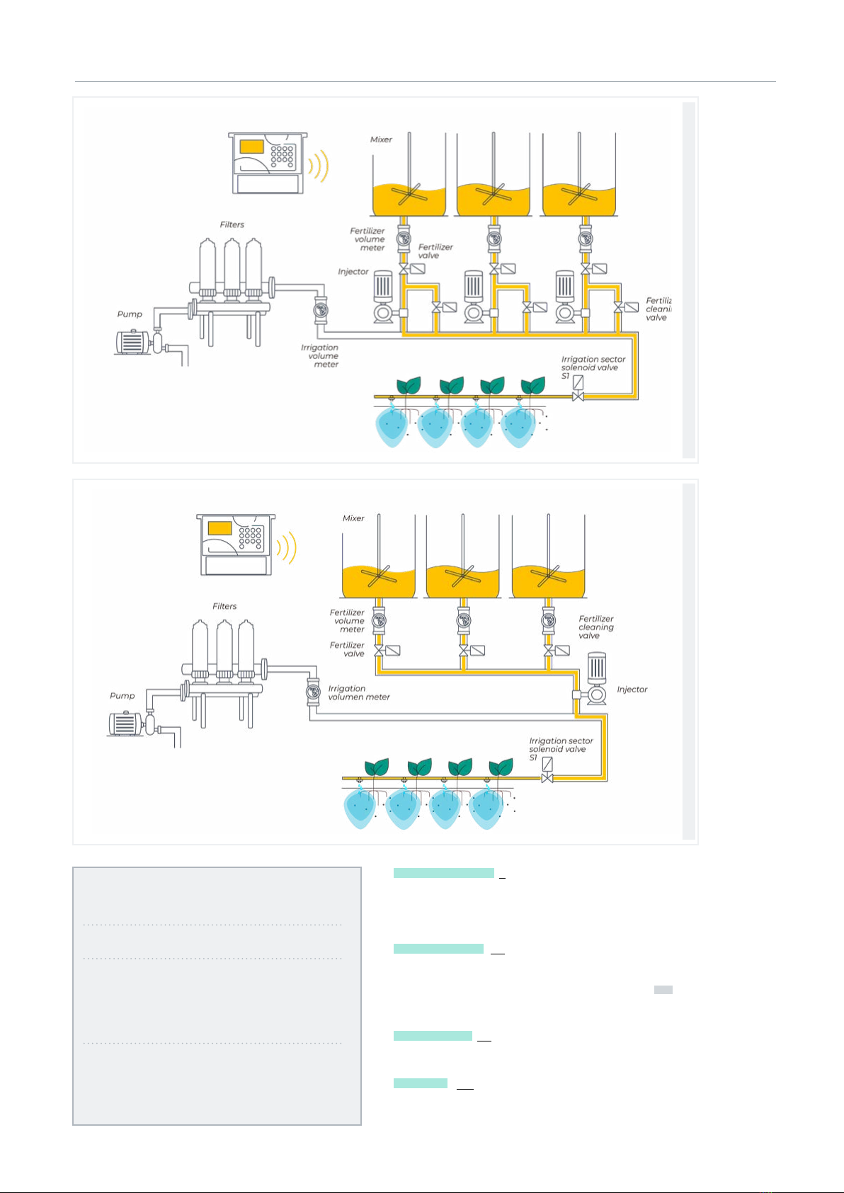
Parallel fertilization
Series fertilization
FERTILIZATION PARAMETERS
N. fertilizers: 4
Fertilizer general: yes
Mixer F1: no
Mixer F2: yes
Mixer F3: yes
Mixer F4: no
Pre-mixing: 015”
Mixing start: 030”
Mixing stop: 120 ”
Last cleaning: 030”
Number of fertilizers (0... 4): enter in the unit the number of
fertilizers installed in the irrigation network.
Leave the value at 0 if there are none.
Fertilizing general (No | Yes): is an output normally used
to connect the injector in series application and is only
activated when one of the fertilizers activates. Enter ‘Yes’ if
it is going to be used.
Fertilizing mixer (No | Yes): each fertilizing can be assigned a
separate mixer. Indicate which fertilizers have a mixer.
Pre-mixing (000 ... 999”): time that the fertilizer will be
stirred before starting fertilization. Pre-mixing comes in
14 User Manual | Agrónic 2500
Parameters | Filters
The Agrónic can control the filter cleaning. Cleaning
can be started manually or automatically.
It starts automatically by a dierential pressure gage
or by an amount of time or a volume of water having
passed through the filters. It will only start automati-
cally if the general one (P1 or P2) assigned to the filters
is activated. In other words, when there is a program
irrigating. It can be started manually whenever desired
from ‘Function - 2. Manual - 4. Filters’.
FILTER PARAMETERS
N. of filters: 5
Initial wait: 000”
Time of activation
by filter: 045”
Pause between filters: 04”
Units between cleanings
Volume: 0000 m3
Time: 0000 ‘
General filter: no
Relationship with P1: yes
Relationship with P2: no
Max. number of continuous
cleanings: 0
Sector stop: no
Number of filters (0 ... 9): number of filters.
Initial wait (000 ... 999”): the waiting time between ac-
tivating the filter general and starting cleaning the first
filter.
5.2. FILTERS
Time of activation by filter (000 ... 999”): time that the
water will pass through each filter to perform cleaning.
Pause between filters (00 ... 99”): waiting time between
closing the cleaning of one filter and activating the
next one.
Units between cleanings (0000 ... 9999): the irrigation
time or volume that must pass through the filters for
automatic cleaning to begin. Time in minutes and
volume in m3.
General of filters (No | Yes): indicate ‘Yes’ to activate an
output during the entire filter washing process.
Relation with P1, P2 (No | Yes): it indicates the pump
from which the water that passes through the filters
comes from. It is used to count units between cleanings
and to run the cleaning.
Maximum number of consecutive cleanings (0 ... 9): if
cleaning is started by the dierential pressure gage
and is always activated, it will do the cleanings config-
ured here at most. It then goes into malfunction and
will not continue cleanings until it is manually recon-
figured. At 0, it never goes into malfunction.
To restart cleaning go to ‘Function - 2. Manual - 4.
Filters’.
Stop of sectors (No | Yes): if cleaning takes place during
irrigation, select whether or not to postpone the irriga-
tion while it does so. It is used when sectors must be
closed during cleaning to maintain pressure.
• Yes: programs that have sectors related to the
pump that use cleaning are postponed. When the
cleaning is finished, the programs continue where
they were.
• No: the programs remain active during cleaning
and the irrigation sectors are not closed.
Video tutorial
available for
this section
before the program starts. If it is less than 10 minutes since
the last irrigation, do not run the pre-mixing.
Mixing during fertilization can be continuous or with
pauses.
Mixing start (000 ... 999”): mixing time before a pause. If con-
tinuous mixing is desired, set the mixing pause to 0 and any
time here.
Mixing stop (000 ... 999”): time that the mixing will be
stopped aer a running time. If continuous mixing is
desired, set this time to 0.
Last cleaning (000 ... 999”): when fertilization ends, the
general and fertilizing cleaning outputs are activated
during this time. If the fertilization is in series, it cleans at
the termination of each fertilizing. If it is in parallel, when
the last one ends.
Watch video
15
Parameters | General
User Manual | Agrónic 2500
5.3. GENERAL
The meter and alarm inputs and the pump, fertilizing,
filter, etc. outputs are configured in this section.
These inputs and outputs must be from the base of
the Agrónic 2500, they cannot be on external modules
such as the AgroBee-L.
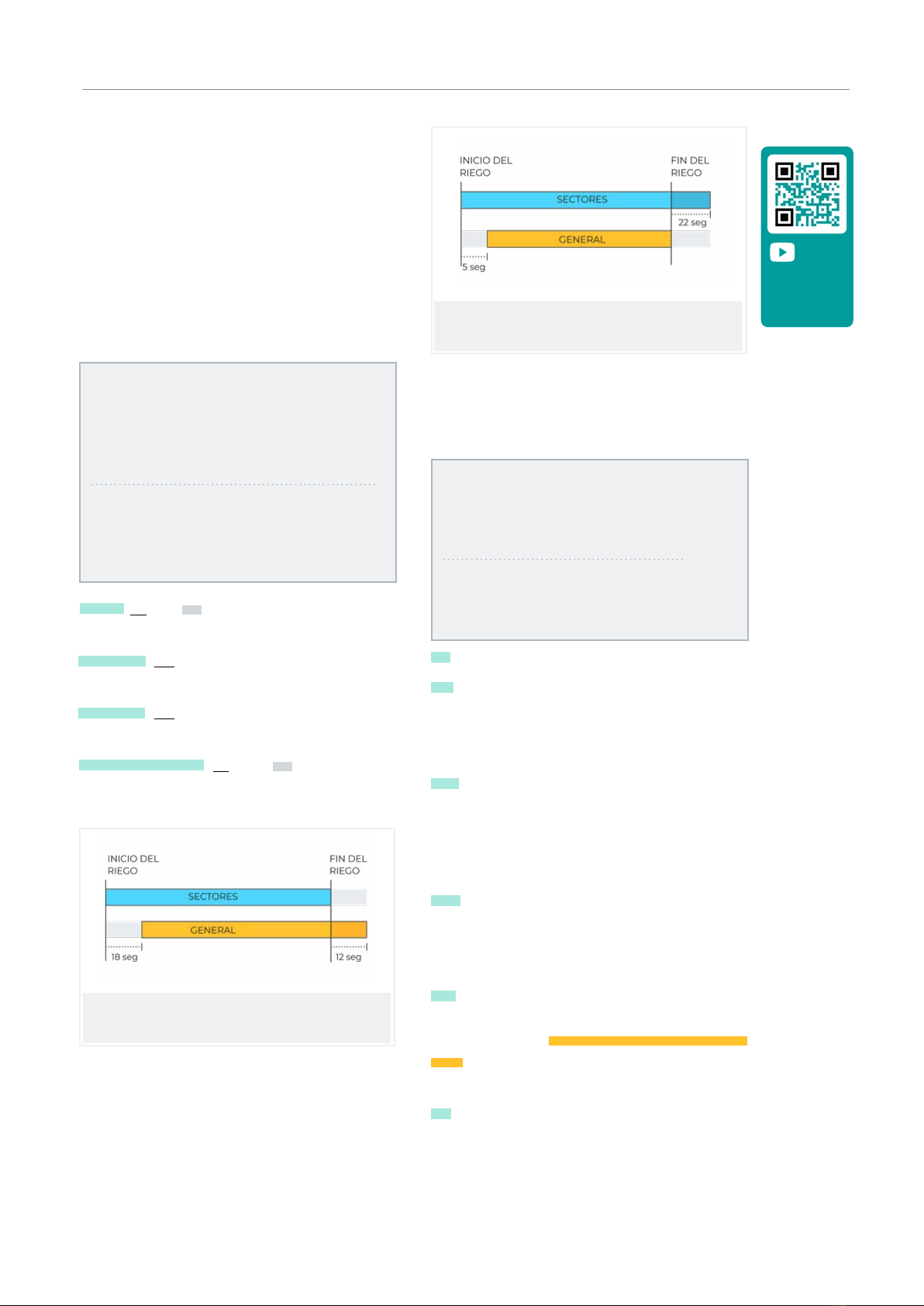
Pumps
Output connected to the drive pumps or general valves.
GENERAL PARAMETERS
Pump 1: yes
Temp. start: 018”
Temp. stop: 012”
Stop in the sectors: no
Pump 2: yes
Temp. start: 005”
Temp. stop: 022”
Stopping the sectors: yes
Pump 1 (No | Yes): yes if pump 1 output is to be used. An
output must be assigned to the pump.
Temp. start (000 ... 250”): time delay in activating the
pump when starting an irrigation.
Temp. stop (000 ... 250”): time that the pump stop is
extended when stopping irrigation.
Stopping the sectors (No | Yes): yes for the pump to
stop when irrigation is finished and for the sectors to
remain open for a few more seconds.
Run timing: 018
Stop timing: 012
Stop in the sectors: no
Run timing: 005
Stop timing: 022
Stop in sectors: yes
Inputs
At the base of the Agrónic 2500 there are 6 digital inputs,
identified as D1 to D6, to connect the following sensors.
GENERAL PARAMETERS
Assign inputs:
IM FM
1 2
Assign inputs:
SC TM DM CS PS AL
4 0 0 5 0 0
IM Irrigation meter.
FM Fertilizing meter 1 to 4, when fertilizing is in series
format, there is only one common meter for all CF fer-
tilizers. For parallel fertilization there will be 4 meters:
cF1 to CF4.
SC Start cleaning. Used to connect a dierential
pressure gage and make cleanings by increasing the
pressure between the inputs and outputs for a group
of filters. The IL input is only taken into account if there
is an irrigation program.
TM Temporary malfunction, it stops the irrigation
program in progress but allows the next sequence
or start to continue. The AT input is only taken into
account if there is an irrigation program.
DM Definitive malfunction, is what causes a total and
definitive stop of the system until it is manually reacti-
vated by the user in ‘Function - 2. Manual - 6. Terminate
stops’. The AD input is only taken into account if there
is an irrigation program.
CS Conditional stop, when activated, all the programs
under way stop completely with their remaining units
intact. Once the stop is over, irrigation resumes at the
same point. While in a conditional stop, programs may
begin and be placed on standby.
Video tutorial
available for
this section
Watch video

16 User Manual | Agrónic 2500
Parameters | Filters
PS Start programs, a digital sensor will begin the ir-
rigation of one or more programs. The input will no
longer be accepted if the programs or their sequences
have not terminated.
AL Alarm, a normally closed digital sensor will send an
SMS when the contact is opened.
GENERAL PARAMETERS
Irrigation meter:
value per pulse: 00100.00 L
Delay without pulse: 010’
Fertilizing meter:
pulse per value: 00001.00 L
Delay without pulse: 010’
Detection delay
Input SC: 030”
Delay, detection
Input TM: 180”
Irrigation meter
The input allows a maximum of 5 pulses per seconds.
Pulse value (00000 ... 90000 L): volume measured by
each pulse.
Delay with no pulse (000 ... 255’): time in minutes that
must transpire without receiving pulses from the meter
for a definitive malfunction to occur and irrigation to
stop (At 0 there is no meter error control).
Fertilizing meter
If the fertilization is in parallel and there are several
meters, they are all are assigned the same values. The
input allows a maximum of 5 pulses per seconds.
Pulse value (00000 ... 90000 L): volume measured by
each pulse.
Delay with no pulse (000 ... 255’): time in minutes that
must transpire without receiving pulses from the
meter to stop fertilization (At 0 there is no meter error
control).
Sensors SC, TM, DM, CS, PS, AL.
Only for sensors that have an input assigned.
Detection delay (000 ... 999”): time in seconds that
the input must be active in order for it to perform the
function.
Outputs
At the base of the Agrónic 2500, there can be up to 27
digital outputs, identified as R1 to R27, to connect the
general outputs. Start with the unit’s last outputs and
reserve the first ones for the sectors.
GENERAL PARAMETERS
Assign outputs:
m1 M2
18 17
Assign outputs:
f1 F2 FG
15 14 16
Assign outputs:
m1 M2 FC
13 12 20
Assign outputs:
c1 C4 GC
10 7 11
Pumps
P1 and P2: outputs connected to pumps or general
valves.
Fertilizers
F1, F2, F3, F4: outputs connected to the fertilizing
injectors.
FG: output connected to the pump or general fertiliz-
ing.
M1, M2, M3, M4: outputs connected to the mixers.
FC: output connected to the fertilizing cleaning valve.
Filter cleaning.
Before assigning the outputs, configure how many
filters there are in the installation. This is assigned in
‘Function - 4. Parameters - 2. Filters’.
C1: output assigned to the first filter.
Cx: output assigned to the last filter.
GC: output connected to the general filter cleaning
valve.
The outputs that occupy the filters between the first
and last are assigned automatically. If there is only one
filter, the last one is not asked.
17
Parameters | Filters
User Manual | Agrónic 2500
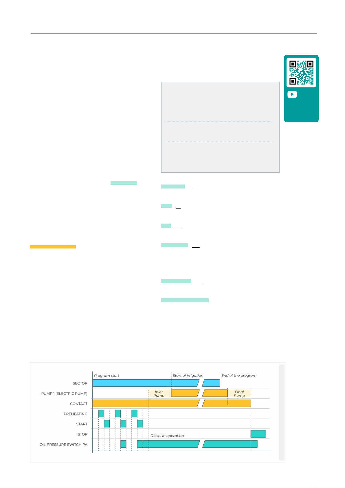
5.3.1 Diesel option
This option is used to start, stop and monitor diesel
pumps for malfunctions.
Operation
The diesel pump is related to pump 1. It starts when a
sector that uses pump 1 opens and stops when the last
sector that uses pump 1 closes.
First the sector is opened, the contact and preheating
output of the diesel pump is activated. When preheat-
ing is finished, the start output activates. If the pressure
gage input is activated, the diesel pump has already
started and irrigation begins. If it is not activated aer
the boot time, wait 30” and attempt another boot. If
the diesel pump cannot be started in 4 attempts, the
stop output is activated, it enters Malfunction and
makes a record. The pump will attempt to start again
at the next irrigation start.
When irrigation is finished, it closes the sectors and
the pump, carrying out the water hammer timings and
once the end of pump time has transpired, it activates
the stop.
‘Consult – 1. General’ shows the status of the diesel
pump.
These screens only appear if the Diesel Option is
activated.
Pressure gage
A pressure gage is used to detect that the pump is
running. Its purpose is twofold: to detect start-up
when attempting to start and, once finished, to detect
insuicient oil pressure. In the Agrónic Basic version,
the pressure gage must be connected to digital input 6
(D6). This input cannot be used for any other function.
If you have a generator on which there is no need to
control the pressure gage input, set the start and stop
times to 0.
GENERAL PARAMETERS
Preheating: 08”
Start-up: 04”
Stop: 060”
Pump input: 085”
Pump end: 0120”
Assign outputs:
ar Pa Co Pr
18 17 16 15
Preheating (00 ... 99”): time that the preheating output
(Pr) is activated before starting the diesel pump.
Start (00 ... 99”): time that the start output (Ar) is
activated to start the diesel pump.
Stop (000 ... 999”): time that the stop output is activated
(Pa) to stop the diesel pump.
Pump input (000 ... 999”): time between when the
diesel pump is running and when the pump 1 output
is activated. It is used to bring the generator set into
operation before starting the pump.
End of pump (000 ... 999”): time between when the
output of pump 1 stops and the diesel pump stops.
Outputs Ar, Pa, Co, Pr: corresponds to the Start, Stop,
Contact and Preheating outputs. If the Agrónic is dual
voltage, these outputs are assigned automatically to
the last four of the unit.
Start/Stop a generator set
Video tutorial
available for
this section
Watch video

18 User Manual | Agrónic 2500
Parameters | Programs
The programs are those that manage crop irrigation
and fertilization. They control the opening and closing
of sectors and fertilization. The Agrónic 2500 has 50
programs.
PROGRAM PARAMETERS
Program: 12
Type of start: [ schedule ]
[ sequential ]
[ input ]
Units of irrigation: [ hh:mm ]
[ m3 ]
Program 12
Pre-irrigation: 00:00
Post-irrigation: 00:00
Program (00 ... 50): program number to be configured.
Start-up type (schedule | sequential | input): determines
how the program is to be started.
• Schedule: starts at a certain time.
• Sequential: starts when another program ends.
• Input: starts when the IP input is activated.
5.4. PROGRAMS
If the Sequential with 99:00 option is activated in
‘Function - 4. Parameters - 8. Installer - 5. Various’,
changing the start schedule to sequential can be
entered in the program. There is no need to do it from
parameters.
Irrigation Units (hh:mm | m3): determines which units
the program will use for irrigation. When the units are
volume (m3), the irrigation meter must be configured.
• hh:mm: hours and minutes.
• m3: cubic meters.
Pre-irrigation (00:00 ... 99:59): time or volume that
must transpire before starting fertilization. The units
and format are the same as irrigation. At 0, fertilization
begins the same as irrigation.
Post-irrigation (00:00 ... 99:59): time or volume that
must transpire between fertilizing termination and
the program termination. The units and format are
the same as irrigation. If fertilizing has not yet finished
when it arrives at post-irrigation, it stops and anomaly
26 is recorded. If irrigating and fertilizing by time and
the fertilization is series or parallel, there is no need to
run pre-irrigation. It is automatically calculated based
on the post-irrigation and fertilization time.
Video tutorial
available for
this section
Watch video

19
Parameters | Sectors
User Manual | Agrónic 2500
The sectors are the outputs where the irrigation valves
are connected. They are related to pumps and the ir-
rigation meter. The history stores the irrigation and
fertilizing that each sector totals. The Agrónic 2500 can
manage up to 30 sectors.
SECTOR PARAMETERS
Sector: 01
Sector: 01
Pump 1: yes
Pump 2: no
Sector: 01
Waterhammer
temporization: +028 “
Meter: yes
Planned flow: 015.50 m3/h
Sector (00 ... 30): sector number to be configured. The
output of the sector is linked to the sector number,
sector 1 with R1, sector 2 with R2, etc. There is an
exception when the Agrónic has AgroBee-L.
5.5. SECTORS
Pump 1 and 2 (No | Yes): yes if the sector requires pump
1 and/or 2 to be activated to irrigate.
Waterhammer timing (-127 ... 000 ... +127”): time in
seconds of delay between the opening and closing of
consecutive and general sectors.
• With positive values, the valve opens immediate-
ly when irrigation starts and stays open for the
number of seconds programmed when it ends.
• With negative values, the opening is delayed for
the number of seconds programmed and when ir-
rigation ends, it closes immediately. There may be
an exception if the sector is the last of an irrigation
sequence and the pump stopping timer is applied.
Meter (No | Yes): yes if the sector will use the irrigation
meter.
Planned flow (000.00 ... 655.00 m3/h): it is the flow
consumed by the sector through drip emitters, sprin-
klers, etc. It is used to distribute the irrigation and
fertilizing volumes in the histories and totals of the
sectors that irrigate at the same time.
Start/Stop a generator set
AgroBee or AgroBee-L option
With this option, the sector valves can communicate
remotely via radio, so that you can configure in the
sector which output the valve will be connected to.
It also enables an auxiliary output that can be common
with other sectors. Activated whenever any of the
sectors that have it configured are activated.
SECTOR PARAMETERS
Sector: 01
N. of output: 00000
N. of output: 00000
The first question about output number corresponds
to the sector and the second to the auxiliary output.
To configure AgroBee or AgroBee-L outputs, see the
table in section ‘6. Input and output coding’.
Video tutorial
available for
this section
Watch video
20 User Manual | Agrónic 2500
Parameters | Various
VARIOUS PARAMETERS
Screen:
automatic shut-o: yes
Illumination: yes
Contrast: 5
Keyboard:
sound level: 2
PIN Security
PIN code: 0000
Screen
Automatic shut-o (No | Yes):
• yes: the screen turns o aer 5’ of not touching any
key.
• No: the screen is always on.
Ilumination (No | Yes):
• yes: the screen has lighting activated.
• No: the screen lighting is stopped.
Contrast (00 ... 05 ... 10): screen contrast level.
5.6. VARIOUS
Keyboard.
Sound level (0 ... 2... 5): duration of the sound when
pressing a key.
PIN security.
Like mobile phones, the Agrónic can be protected with
a PIN code so that it cannot be used if it is stolen. If
the Agrónic is without power for more than 10 minutes,
the PIN code will be requested when it is powered
again. If the correct code is not entered three times,
the Agrónic is blocked and the deactivation code (PUK)
is requested. To get the code, please contact Progrés.
Even if the Agrónic is blocked, the programs continue
to run normally and it will operate normally if there is a
connection to Agrónic APP/VEGGA/Agrónic PC.
To change the PIN code, first enter the current PIN,
otherwise it cannot be changed.
PIN code (0000 ... 9999): security code. At 0 PIN protec-
tion will not be used.
Video tutorial
available for
this section
Video tutorial
available for
this section
The Communications Query
section is detailed in the
Communications Manual r1850
Watch video
Watch video
See Communications Manual
Other manuals for AGRONIC 2500
3
Table of contents
Other Progres Farm Equipment manuals


