Progres AgroBee-L User manual
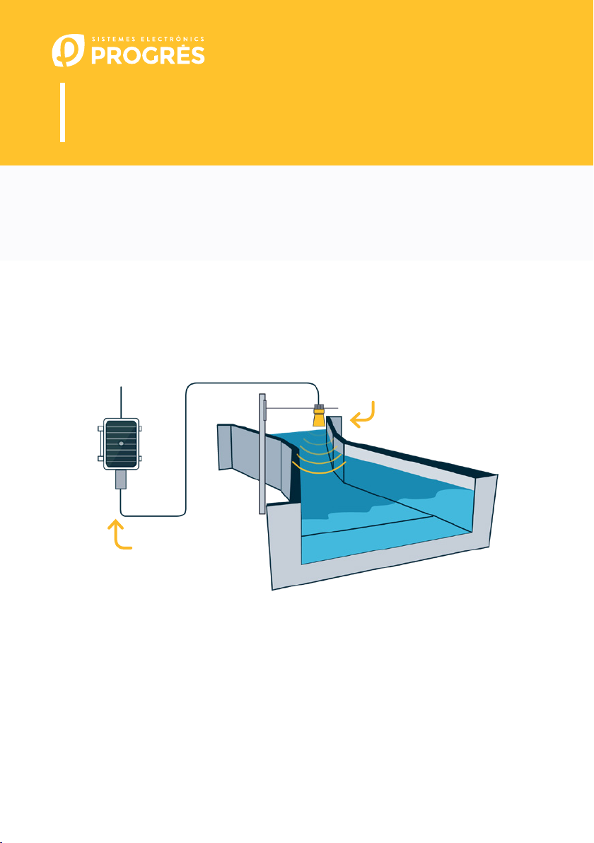
AgroBee-L Parshall System
AgroBee-L Manual
Very low consumption radio modules and integrated parts of the
AgroBee-L system for open canal flows based on Parshall gauges
through an ultrasonic sensor that forms part of the controller.
The AgroBee-L Parshall model oers the following, according to the available format:
• 1 ultrasonic sensor:
‒ 1 sensor with TTL output for measurements up to 9 metres with 1mm precision
N P K
AgroBee-L
Parshall
Ultrasonic sensor
The Parshall canal is a standardized Venturi canal. Parshall gauges are calibrated instruments
for measuring flows in open canals. It is technically described as a critical depth gauge. Its main
advantages are that there is only a small pressure drop through the gauge, which allows for the
easy passage of sediment or debris, without needing special access conditions or a buer well or
even corrections for up to 60% submergence. Consequently, it is suitable for measuring the flow
in irrigation canals or natural currents with a gentle slope.
The meter consists of a section convergent with the bottom level, a funnel section with a des-
cending slope on the bottom, and a divergent section with an ascending slope at the bottom.
Thanks to this, the water drains at a critical speed through the funnel.

2· User’s manual | AgroBee-L
b[“] b[m] C n F[m]
sensor position
1 0.0254 0.001352 1.548 0.242
2 0.0508 0.002702 1.548 0.276
3 0.0762 0.003965 1.548 0.311
6 0.1524 0.006937 1.574 0.414
9 0.2286 0.013762 1.528 0.587
12 0.3048 0.69 1.519 0.914
18 0.4572 1.06 1.538 0.965
24 0.6096 1.43 1.550 1.016
30 0.7620 1.81 1.558 1.067
36 0.9144 2.18 1.566 1.118
48 1.2192 2.95 1.578 1.219
60 1.5240 3.73 1.587 1.321
72 1.8288 4.52 1.595 1.422
84 2.1336 5.31 1.601 1.524
96 2.4384 6.11 1.607 1.626
120 3.0480 7.46 1.600 1.829
144 3.6576 8.86 1.600 2.032
180 4.5720 10.96 1.600 2.337
240 6.0960 14.45 1.600 2.845
300 7.6200 17.94 1.600 3.353
360 9.1440 21.44 1.600 3.861
480 12.1920 28.43 1.600 4.877
600 15.2400 35.41 1.600 5.893
The meter’s control section is located near the end of the converging section. The Parshall
gauges are calibrated for a piezometric height ha, measured at a defined place in the converging
section.
Parshall gauges are constructed in very dierent sizes and classified according to the width,
b, in the funnel section. For each of them, a pair of constants is defined which, along with the
measured water height, allow you to determine the flow of water through the gauge:
The AgroBee-L Parshall model’s ultrasonic sensor directly measures the distance between
the sensor and the surface of the water. The measurement of water flow through the canal in
question is obtained through this process and from the configuration parameters entered into
the associated controller.
The sensor must be installed at 2/3 of the total convergence section, as indicated in the
following figure (distance F shown in the previous table):
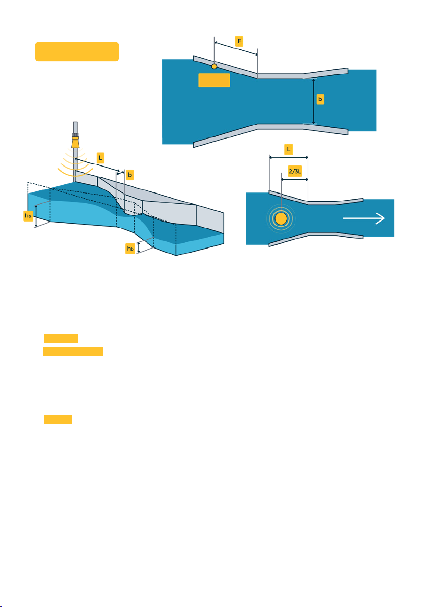
User’s manual | AgroBee-L · 3
Q = C x han
This module is powered by a 1.05 W solar panel + supercapacitors, already incorporated into
the controller (no need to replace batteries).
For the sensor, the following parameters must be entered in the controller, which will let you
determine the water flow of the canal in question:
• Width [”]: dimensions of the Parshall canal, in inches, and according to the previous table.
• Total height [m]: distance from the sensor at level 0.
Example: with the sensor located at the top of a canal to measure its water level, the total
height will be the distance from the sensor to the bottom of the canal.
The water flow can be calculated from this information along with the measurement from the
sensor.
• Format: presentation format of the measured flow data: in m3/h, m3/s, l/s, or gpm. For each
of these formats, you can also choose the given resolution. You can choose one resolution or
another depending on the units chosen and the maximum value of the flow to be measured
in the system in question. It is important to keep the maximum possible value for the
formats in mind, which is also indicated below:
‒ 00000 (max. 32767)
‒ 0000.0 (max. 3267.7)
‒ 000.00 (max. 327.67)
These sensors’ reading rates can be selected from 3 dierent values: 5, 10, or 20 minutes, with
the default value being 5 minutes.
Material supplied along with the purchase of the AgroBee-L Parshall: Sensor, 7 metres of wiring,
and support for the sensor.
MEASURE
POINT
4· User’s manual | AgroBee-L
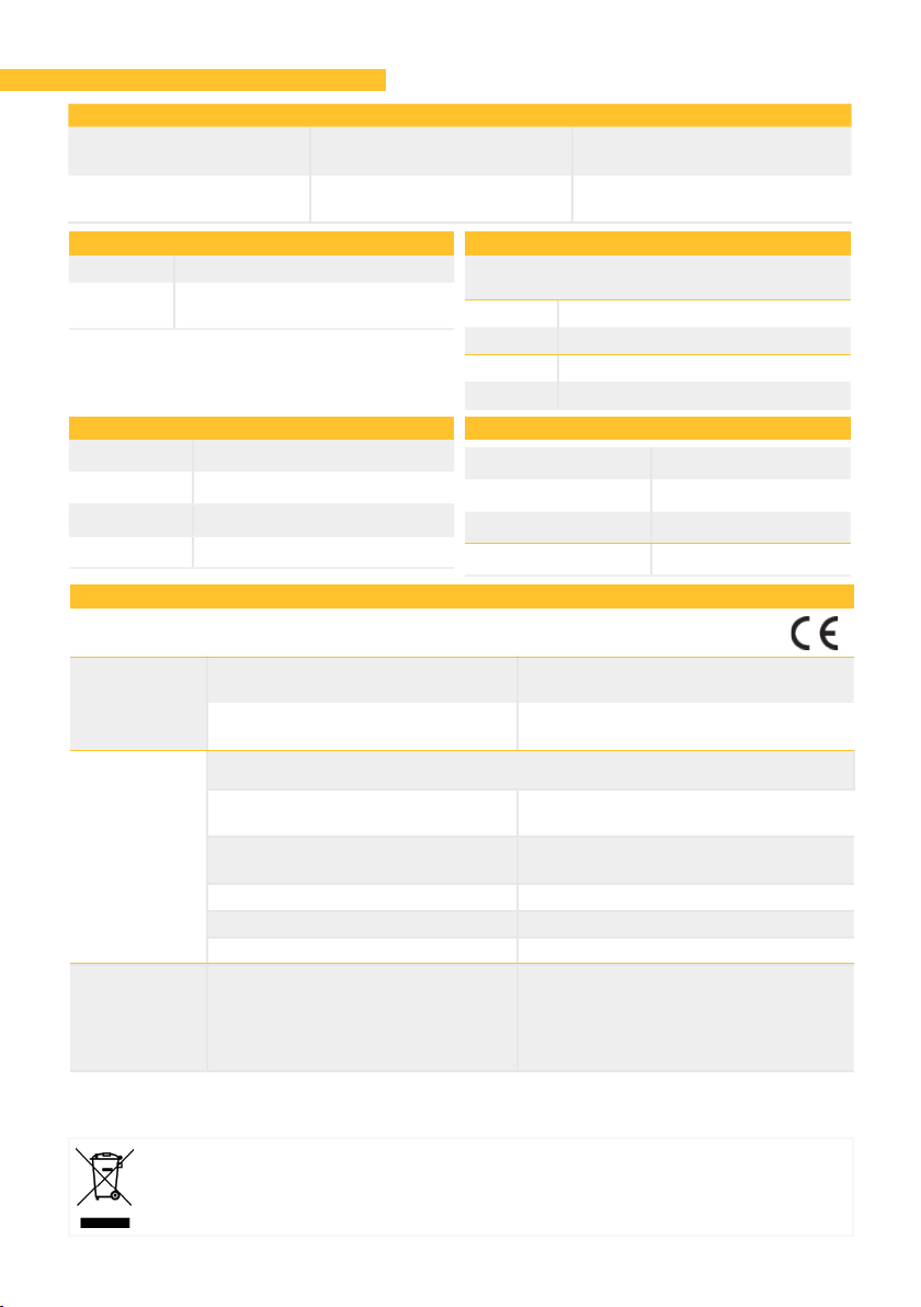
Technical characteristics
Power supply: Parshall: Solar: 5V /
1,05W → 3,3V Panel plus high capacity
supercapacitors
Energy consumption:
Parshall Average consumption:
0,90 mW
Power supply
Number 1
Type 5 Vcc (Sensor power supply)
Maximum current: 50 mA
Outputs
Temperature -10 °C a +60 °C
Moisture < 95 %
Altitude 2000 m
Pollution Grade II
Environment
Height 150 mm
Width 100 mm
Depth 70 mm
Weight (approx.) 0,4 Kg
Box dimensions Parshall
Maximum distance betweeen sensor and
AgroBee-L: 50m
Number 1
Type For potential-free contacts
Number 1
Type Digital (TTL)
Inputs
This symbol indicates that electrical and electronic controller must not be disposed of along
with household waste at the end of its useful life. The product must be taken to the correspon-
ding collection point for the recycling and proper treatment of electrical and electronic contro-
ller in accordance with national legislation.
This system conforms with the regulations and other
regulatory documents in the following list:
Electrical
safety
UNE EN 60950-1:2007+ CORR:2007 Information technology controller.
Safety. Part I: General requirements
UNE EN 60215:1995 + A2:1995 Safety requirements for
radiotransmission controller
EMC
ETSI EN 301 489-17 v1.3.2 based on ETSI EN 301 489-1 v.1.7.1:
UNE-EN 55016-2-3:2007 Radiated radio frequency
emissions (30-1000MHz). Class B
UNE-EN 61000-4-2:1997
+ A1:1999 + A2:2001 Electrostatic discharge
UNE-EN 61000-4-3:2007 + A1:2008 Electromagnetic field immunity
UNE-EN 61000-4-4:2005 Transient/burst immunity
UNE-EN 61000-4-6:2008 Current injection: 150KHz-80MHz
Radio
spectrum
protection
ETSI EN 300 328 v1.7.1
(Decision ERC/DEC/(01)07
and Recommendation
CEPT ERC/REC 70-03)
Spurious issuer emissions Coordinator
and Module Parshall. Eective
radiated power Coordinator and
Module Parshall. Frequency dri
Coordinator and Module Parshall.
Declaration of conformity

User’s manual | AgroBee-L · 5
Inputs
The AgroBee-L radio modules are used for the activation of valves and other irrigation elements,
as well as the reading of sensors and meters. It is very low consumption and follows the LoRa
radio modulation, which operates in the 868MHz, 433 MHz and 915 MHz, free bands, obtaining
radio coverage of up to 2500 m between two points (depending on the orography).
AgroBee-L System Operation
Currently, they can be incorporated into the Agrónic
2500, Agrónic 5500 and Agrónic Bit Con fertirrigation con-
trollers.
The AgroBee-L system consists of a coordinator device
(located in the Agrónic 2500, Agrónic 5500 or Agrónic
Bit Con controllers) and by field elements with dierent
functions, depending on the model in question. This
system does not include the use of repeater elements,
so all modules must connect directly with their coor-
dinator. The field modules manage their consumption
by activating the communication in the precise time of
the exchange; the rest of the time, they are asleep or
attending to irrigation control.
Its low consumption allows it to operate with a solar panel integrated into the module and
supercapacitors or battery (depending on the model). The solar panel stores the energy in the
supercapacitors/battery, oering a long operational life. It is only necessary to replace batteries
in models that include batteries instead of supercapacitors.
The maximum number of modules that an Agrónic controller can manage is 20 units in standard
mode, which can be configured as modules of any of the available types. There is also a priority
mode, which makes it possible for the modules to communicate more oen: in this case, the
number of modules (10) is halved.
To use AgroBee-L modules, it is necessary to assign their outputs to the sectors or generals of
the controller in question, and their inputs to the digital, analog, or counters sensors.
The AgroBee-L system has the following features, among others:
• Operation in 868 MHz, 433 MHz and 915 MHz free bands.
• Availability of 13 communication channels plus 18 transmission modes, which allow for the
operation of more than one network in the same area working on the same channel.
• Availability of network code, which allows for filtering the information of several networks
configured with the same parameters.
• Self-adjustable communication rate according to the chosen transmission mode and the
timing mode:
‒ Timing in standard mode (60 –200”). Up to 20 modules.
‒ Timing in priority mode (30 –100”). Up to 10 modules.
6· User’s manual | AgroBee-L
Installation
For the supply of radio controller, it is essential to have a
coverage study. This study verifies the viability of the system
according to the profile of the terrain, the location of the points
to be controlled, and the distance between them. The study is
delivered along with the controller oer.
AgroBee 868 MHz
ESTUDIO DE COBERTURA RADIO
SISTEMES ELECTRÒNICS PROGRÉS, S.A.
El resultado del estudio es
VIABLE
Referencia FINCA RIO GRANDE
Número de estudio
2017 - 001
Instalador AGUAS DEL NORTE
Fecha de creación
05/12/2017
Distribución
instalación
Indicaciones para su correcta instalación
Coordinador altura mínima 6m - cable subministrado 10 m
Otros módulos altura mínima 4.5m - cable subministrado 10 m
Módulo Repetidor altura mínima 6m - sin cable
Garantizar visión directa entre antenas
Comunicación indirecta del coordinador a los módulos, comunicación mediante repetidor
Coordenadas Módulos RPT-EXTERNO 38°50’42.57”N - 6°19’4.14”O
Altura
Visibilidad
Distribución directa entre antenas
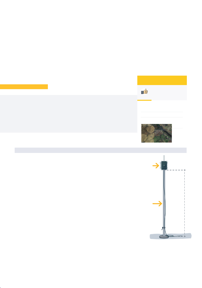
The AgroBee-L modules have the antenna integrated into the
module, so they are installed on top of a post.
For good radio communication, it is very important to place the
modules in areas free of vegetation, walls, and metal structures.
The minimum recommended height to place the module is 4.5
metres from the ground. If there are tall crops (corn, trees, ...) this
minimum height of the module must be increased by 2 metres
above the height of the crop. In all cases, it must always have
direct visibility with the controller’s antenna that sends the in-
formation (coordinator located in Agrónic). The 7 metres of cable
supplied already include these assembly recommendations.
To increase the coverage, and if necessary, the best system is
made by raising the module as high as the length of the cable allows.
The modules with solar panels must be placed orienting the panel to the South (Northern he-
misphere) or North (Southern hemisphere) to obtain the best solar coverage.
min. 4,5 m
Post
Module
INSTALLATION MÓDULOS
• Distances of up to 2500 metres between any module and its coordinator (depending on the
orography).
• Manual actions, consultations, and configuration of the network number, channel,
transmission mode, and communication timing (standard/priority):
‒ In-situ: Through the Module Reader
‒ From a distance: Through the Agrónic
• Battery/charge level reading and solar panel (if any).
• Reading SNR level (signal-to-noise ratio) reception in the module and coordinator (in [%]).
• Reading the status of the last 16 communications and remaining time indicator until the
next communication.

User’s manual | AgroBee-L · 7
min. 2 m
Flange Folding posts
To keep it watertight, it is necessary to always
leave the lid closed.
The modules can be fixed on a 35 to 45mm post by
means of the support and flange, incorporated in
such a way that the cable output passes through the
inside of the post.
It is recommended to install it on folding or exten-
dible posts for easy access to the module.
Ultrasound sensors should always be installed at a
distance greater than 50 cm from the nearest surface
to be measured. In the case of the Parshall canal,
the sensor must be placed at least 50 cm above the
maximum level at which it can be.
IMPORTANT
The sensor must be well-fixed in its location by
means of the mount provided. It is important that it
be well-secured and not move at all, since this would
alter the result of the measurements.
There must be no object between the sensor and
the surface to be measured.
INSTALLATION SENSORS DE ULTRASONIDOS
Do not place the sensor next to a wall
or any other surface that is parallel to
the sensor’s central axis. The minimum
distance that a sensor must be with
respect to any surface parallel to its axis is
defined by the supplied mount.
Minimum radius
Maximum
level
Minimum
distance
Level
sensor
min. 50 cm
min. 50 cm min. 50 cm
Minimum
radius
min. 50 cm

8· User’s manual | AgroBee-L
Inputs and Outputs
Parshall
Wire colour Function (digital input)
Brown Common Digital Input
Blue Digital Input 1
There is 1 digital input in an
AgroBee-L Parshall module, which
can function either as a digital input
or a counter/rain gauge input.
When the input is connected to
DIGITAL INPUTS DIGITAL SENSOR
a counter, the minimum time between pulses must be 0.1 seconds and an anti-bounce filter
may be enabled in order to avoid accumulating undesired pulses. Maximum allowed distance
between AgroBee-L module and a digital sensor or meter is 50m.
The said input’s connection must be set according to the following table. The digital input’s
wire connection is coloured Blue. The common input is the Brown wire.
Settings
For any AgroBee-L module to enter the correct operating mode, you must have an Agrónic
controller (Agrónic 2500, Agrónic 5500 and Agrónic Bit Con) with the AgroBee-L option installed,
which includes the internal coordinator and an antenna with 10 metres of cable. This can be
verified by doing the following in the controller:
Consulta Comunicación AgroBee-L Status: Correct
In the same way, a module must be configured to communicate with the Agrónic with which
you want to associate it. To do this (if the module is not already configured at the factory) you
must use the Module Reader (or Agronic Radio Reader, LAR) consisting of a screen and four keys,
that is connected to the AgroBee-L module through the only connector visible on the inside.
A wireless module reader is also available that allows you to perform functions without the
need for a cable. Consult the wireless AgroBee Reader manual to learn about the steps to link it
to the controller.
The sensor is supplied with a 7 metre hose that is already connected to the AgroBee-L Parshall,
so it is not necessary to make any additional connection. A mount is also provided to facilitate
the sensor’s installation.
CONNECTED SENSOR
This model has 1 input for reading an ultrasonic sensor. The module is supplied with 1 sensor:
• 1 sensor with TTL output for measurements up to 9 metres with 1mm precision
For this module, no action must be taken to connect the inputs, since the Parshall model is
already supplied with 1 connected sensor.
DIGITALTTL INPUTS ULTRASOUND SENSORS

User’s manual | AgroBee-L · 9
Once the AgroBee-L module is linked with an Agrónic, all the consultations and
parameters are accessible through the Agrónic.
NOTE
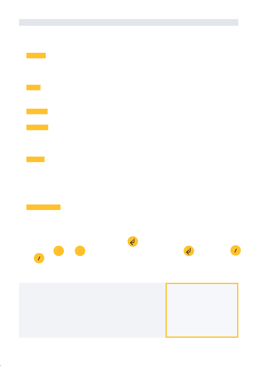
Press the key to enter the main menu. Use the and
keys to change the options within the menu. Use the key to
enter the selected menu option. Use the key to return to the
previous hierarchy’s menu.
You will see the following options in the main menu:
• Consult controller
• Consult communications
• Consult digital and analog inputs
• Communication parameters
• Input-Output parameters
• Various parameters
+
-
cc
General query menu of the module, where the following parameters are displayed:
• Module and serial number:
‒ Module: It refers to the module number (1 to 20) according to the established
communication parameters. There can only be one same module number for each
Agrónic.
‒ Serial number: Information regarding the controller. It comes from the factory.
• Battery voltage and solar panel:
‒ Vbat: Battery voltage:
∙ Panel+Supercapacitors: Maximum value: 3.4V; Minimum value: 2.2V
∙ Panel+Battery: Maximum value: 4.2V; Minimum value 3.4V
‒ Vsol: Voltage of the solar panel
These same data can be viewed in the Agrónic by accessing “Consult - Communications -
AgroBee,” as you will see in the next section.
CONTROLLER QUERY OF AN AGROBEEL MODULE
Communication consultation menu of the module, where the following parameters are
displayed:
• Transceiver: Type of emitter installed in the module. It tells you if the module works at
868MHz/433MHz or 915MHz
CONSULT COMMUNICATIONS IN AN AGROBEEL MODULE

10 · User’s manual | AgroBee-L
‒ RN2483 (868MHz/433MHz)
‒ RN2903 (915MHz)
• Band and transmission mode:
‒ Band: 868MHz, 433MHz, 915MHz
‒ Transmission Mode: 1 to 18 (mode 5 will be set by default)
• Consult parameters of the communication type:
‒ Channel: 1 to 13
‒ Network code: It is usually the associated Agrónic serial number
‒ BW: Bandwidth of the radio modulation (125KHz, 250KHz, 500KHz). It is set according to
the transmission mode chosen in the communication parameters.
‒ Radio modulation factor: SF7, SF8,…, SF12. It is set according to the transmission mode
chosen in the communication parameters.
‒ Communication status:
∙ Status message:
- Correct Communication
- Network error
- Communication error
- Model error
- Does not communicate
∙ Signal-Noise ratio of the last received message: Reliable communication if >40%.
‒ Time until next radio emission: time in [s]
‒ Status of the last 16 communications (the previous communications appear on the right
side of the screen):
∙ 1: It indicates that the emission has been made and the correct information received in
the last communication
∙ 0: Indicates that the radio emission has been made, but the correct data has not been
received or no data has been received
Part of this information is available through the Agrónic by accessing “Consultation | Commu-
nications | AgroBee”, where you can also see the query regarding the controller and the parame-
ters of the communication.
CONSULT COMMUNICATIONS
AgroBee-L 868
Status: Correct
Timing: 60”
Channel: 01 TX Mode: 05
Network code: 00001
CONSULT COMMUNICATIONS
M01 (ns. 236) V1.00
Status: Correct (40”)
Level: 80% / 82%
Vbat: 04.0 V Vsol: 05.8 V
1111111111111111

User’s manual | AgroBee-L · 11
AgroBee-L 02 Parshall
EA: 963
Vsen: 5125
Error: 0
ED: 1
Menu to check the status of digital inputs, counters, and Parshall inputs.
The information shown on the dierent screens is as follows:
• Check digital inputs: For each of the digital inputs available to the module in question, its
status is shown either as ‘0’ (open contact) or ‘1’ (closed contact).
• See accumulated counter sensors: The total number of pulses detected will be displayed for
each digital input configured as a counter sensor. If this entry is not configured as a counter,
the text ‘N-A’ (Not-Activated) will appear.
• See instant flow rate (time between pulses): The time in [ms] between the last 2 pulses
detected will be displayed for each digital input that is configured as a counter sensor. If this
entry is not configured as a counter, the text ‘N-A’ (Not-Activated) will appear.
• Consult flow rate given by ultrasonic sensor: Measured value of the flow according to the
established presentation format.
• Check the supply voltage of the analog sensors: The value of the supply voltage sent to the
active analog ultrasonic sensors is displayed in [mV].
From the Agrónic, press the ‘1’ key in the module’s consultation screen on the Agrónic to view
the analog/digital inputs.
Nomenclature used in these queries:
• EA Analog input values in millivolts. Refers to the direct value of the flow measured in the
CONSULT THE AGROBEEL MODULE DIGITAL AND ANALOGUE INPUTS
Parshall canal.
• ED status of digital inputs. With a ‘1’ indicating that the contact is closed and a ‘0,’ that it is
open.
• Vsen value of the voltage in mV supplied to the sensors.
• Error sensor reading status. With a ‘1’ indicating that there has been an error in the reading
of ultrasonic sensors.
12 · User’s manual | AgroBee-L
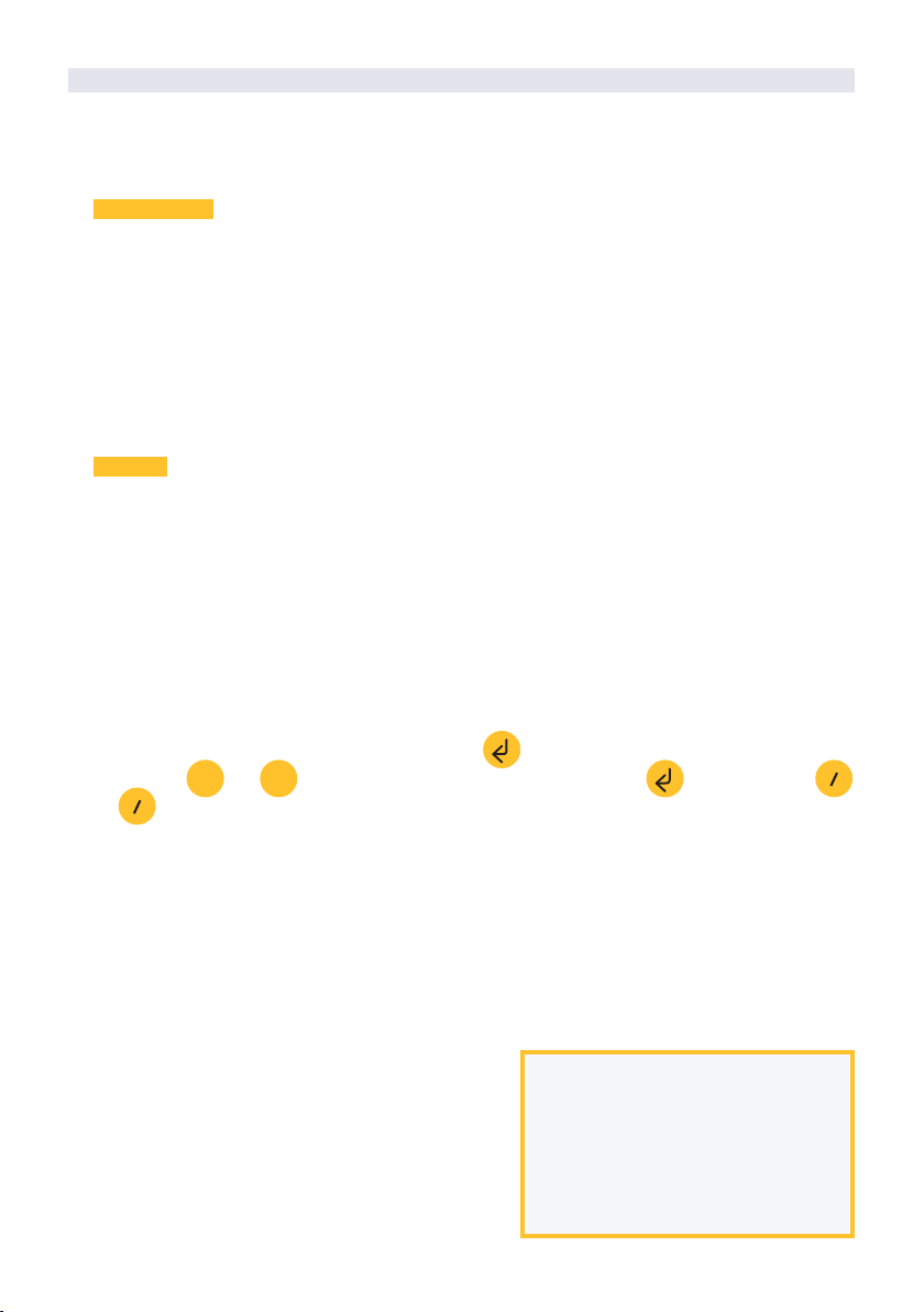
To modify any of the sub-menu’s fields, press . The screen will display that you are in edit
mode. Use the and keys to set the desired value. Confirm with or dismiss with .
Press to exit the menu and access the previous hierarchy’s menu, which will change the para-
meters and let them take eect.
For an AgroBee-L module to establish communication
with a certain Agrónic, you must set, through the reader,
the parameters that have just been described, according
to those established in the Agrónic in question. In the
Agrónic, you can modify these parameters in ‘Parameters
| Installer | Communications | AgroBee | Coordinator’:
AgroBee-L
Channel: 01
Network code: 00001
Timing: standard
Band: 868MHz
TX Mode: 05
The following parameters are in the Communication Parameters menu of the Module Reader,
which allow you to establish the communication of a certain AgroBee-L module with a controller:
• Module Module number in the network. It is used to distinguish all modules that may be
associated with an Agrónic. The module number cannot be repeated in the same Agrónic:
‒ 1 to 20 (timing in normal mode)
‒ 1 to 10 (timing in priority mode)
• Band Frequency Band:
‒ 868MHz or 915MHz (default value, depending on the model)
‒ 433MHz (only available in models that also support 868MHz band)
• Channel Frequency channel number:
‒ 1 to 13 (independent from the band used)
• TX Mode Transmission method. Set the radio’s transmission and reception parameters.
‒ 1 to 18 (mode 5 set by default):
∙ Mode 1: The shortest coverage length permitting the lowest lag time
∙ Mode 18: The greatest coverage length, but with the most lag time
• Timing 2 timing modes:
‒ Normal mode (recommended): It is automatically set according to the chosen
transmission mode, but always includes the communication of up to 20 modules. Value
between 60” and 200”.
‒ Priority mode: It is automatically set according to the chosen transmission mode and
includes the communication of up to 10 modules. Value between 30” and 100”.
• Network code It dierentiates the information from several controllers with the same
communication parameters (band, channel, and transmission mode). The Agrónic serial
number is assigned by default.
COMMUNICATION PARAMETERS OF AN AGROBEEL MODULE
+
-cc
cc
User’s manual | AgroBee-L · 13
AgroBee-L 01
Timing: 05’
Width: 1”
Total height: 0001 mm
Format: 000.00 m3/h
IMPORTANT
The detailed input/output parameters can also be entered in the Agrónic. In this case, the
module will receive the parameters upon communicating with it. If not, and these parameters
have been changed through the Module Reader in the same module, the Agrónic will receive and
update said parameters.
To modify these parameters from the Agrónic,
you must access “Parameters – Installer – Commu-
nications – AgroBee – Module.” Specify the module
number in the Agrónic network in question, aer
which you will see the following screens to modify
the detailed parameters (see the Agrónic manual
in question for more details).
INPUTOUTPUT PARAMETERS OF AN AGROBEEL MODULE
In the Input-Output Parameters menu of the Module Reader, you can set the parameters
of the AgroBee-L module’s different inputs and outputs, available through the following
sub-menu:
• Digital Inputs Configuration of digital sensors or counters.
‒ Configuration of functions of each of the available digital inputs:
∙ Digital input
∙ Counter
‒ Anti-bounce filter: only applicable when digital input is setup as counter. A filter time
between 0.0” and 10.0” can be fixed, and it represents the minimum time that a contact
must be closed to count a new pulse. Same time is considered for all the inputs of the
module. This filter time can only be setup by using the Module Reader (it cannot be setup
from the programmer to which this module is linked).
• Sensors Configuration of ultrasonic sensors. You will have the following options:
‒ Parshall: Width of the Parshall canal. From 1” to 600”.
‒ Format for showing the flow reading:
‒ Total height in [mm]
‒ Reading rate: 5min (default), 10min, 20min
To modify a field of any of the parameters, press . The screen indicates that you are in edit
mode. Use the and keys to set the desired value. Confirm with or dismiss with .
Press to exit the menu and access the previous hierarchy’s menu, which will change the
parameters and let them take eect.
“000.00 m3/h”
“000.00 m3/s”
“000.00 l/s”
“000.00 GPM”
“0000.0 m3/h”
“0000.0 m3/s”
“0000.0 l/s”
“0000.0 GPM”
“0000 m3/h”
“0000 m3/s”
“0000 l/s”
“0000 GPM”
+
-
cc
cc

14 · User’s manual | AgroBee-L
• Width Width of the Parshall gauge. From 1” to 600”.
• Total height height Value, in metres, of the distance between the sensor and the farthest
limit of measurement. In a Parshall canal, the total height is the distance between the
sensor and the bottom of the canal.
• Surface Format of the flow rate consultation reading.
These parameters are not used directly by the Parshall module. It is the Agrónic which, based
on these parameters and the reading provided by the Parshall module, calculates the water
height and remaining volume.
FORMATS OF THE MODULE SENSORS:
The AgroBee-L Parshall module comes with 1 physical ultrasonic sensor. Now, the value of the
flow measured through a Parshall canal is obtained by means of the “width”, “total height”, and
“format” data that are entered.
The notation of the inputs and outputs of the dierent Progrés controllers follows a standard
format. As an example, the coding of the analog inputs corresponding to a Parshall module in an
Agrónic 2500 is as follows (see section “Parameters - Analog sensors” in the User Manual with the
additional A-2500 / R-1751 option):
Parshall analog inputs notation
Input Codes Parameter
30101 Direct measurement of the flow according to the established format
As you can see, the numbers of entries are encoded in five digits: the most significant indicates
the device: in this case, AgroBee-L; the next two digits are used to identify the dierent AgroBee-L
modules of an Agrónic; and the last ones are the entry number. In the previous table, the sensor
refers to the AgroBee 1 module.
VARIOUS PARAMETERS OF AN AGROBEEL MODULE
In the Various Parameters menu of the Module Reader, you can select the language among
Spanish, Catalan, English, French, Italian, and Portuguese.
From this menu, you can also can completely erase the module’s data, restoring it to factory
settings, maintaining the serial number and the model.
Consultation Communications AgroBee-L
(down and up arrow to go through the dierent modules)

You have already seen how to consult the dierent parameters of an AgroBee-L module through
the Module Reader. In the Agronic to which the AgroBee-L module is associated, it also shows the
battery information and radio link performance of said module.
The information provided is:
• Module number, serial number, and firmware version
• Signal level received by the Agrónic and the module. It is displayed in % and indicates the
level of the signal-to-noise ratio.
• Advisable/recommended value > 40%
• Vbat: Battery level in mV:
‒ Module with panel + supercapacitors: VBat max = 3.4 V; VBat min = 2.2 V.
• VSol: Voltage level delivered by the solar panel.
Battery levels and radio signal/quality
Consultation Communications AgroBee-L
(down and up arrow to go through the dierent modules)
(1): The duration of the battery with its maximum charge and without recharging. This case can occur when the solar panel
does not recharge the battery (with clouds or fog).
Battery life with standard communication rate mode 5: 60 seconds
Type Parshall
Panel + Supercapacitors(1) < 3 days
Estimated battery life
If a module does not find the Agronic with which it communicates, said module will follow its
own course, and will send data every certain time, according to the established timing. However,
in order to avoid possible collisions and/or interferences, the module will slightly oset the
pre-established communication time. The consumption of an AgroBee-L module is practically
unchanged due to the fact that it is not connected to any Agrónic.
TURNING OFF THE CONTROLLER
Battery life is approximate since there are several factors that can aect consumption. Frequent
reading of digital sensors (when counters are configured) shortens the duration. Likewise, if a
priority mode rate is set, the battery life will decrease.
Conversely, for the Parshall model, if a higher sensor reading rate is selected, the battery life
will increase.
Battery replacement you do not need to replace any battery in any case, since the power
supply of the modules is based on a system of supercapacitors.

Updating the AgroBee-L module software
Whenever there is a new soware version for an AgroBee-L module, the user can update it. To
do this, you must perform the following steps:
• Have a computer with an Internet connection and a
USB to miniUSB cable.
• Download the program “AgronicUpg” + “drivers”
+ update file (dfu) by typing this address bit.ly/
actualizaragronic into the computer’s browser.
• Select and download the AgroBee-L folder.
• Go to the module and turn it o using the switch.
• Place the other switch inside the module in the
recording position (by default, it is in the ‘Normal’
position).
• Connect the USB to the computer and the miniUSB
to the module.
• Start up the module using the ON/OFF switch.
• On the computer, run the program “AgronicUpg”.
If you do not see the “Internal Flash” line on the
screen as seen in the image, you must install the
Mini USB
Normal Record
Switch
ON
OFF
“xxx.dfu”. Once loaded, press the “Update” button and wait for the process to finish.
• Once the process is finished, the module is updated.
• To finish, turn o the module, disconnect the miniUSB cable, and place the second switch in
the ‘Normal’ position.
• Finally, the module can be started up again.
drivers. If you already have the drivers installed, skip
to the next step.
• To install the drivers, go to the files you have
downloaded and select the folder that corresponds
to your Windows version. Run the file “dpinst_” and
follow the steps. If you use Windows XP, call Progrés
to help you with the installation.
• Press the “Choose file” button and select the file
R-2174-2
Polígon Industrial, C/ de la Coma, 2 | 25243 El Palau d’Anglesola | Lleida | España
Tel. +34 973 32 04 29 | info@progres.es | www.progres.es
Sistemes Electrònics Progrés, S.A.
Other manuals for AgroBee-L
1
Table of contents
Other Progres Farm Equipment manuals


Popular Farm Equipment manuals by other brands

HAUL MASTER
HAUL MASTER 68895 Owner's manual & safety instructions

Unverferth
Unverferth NutriMax 1800 Operator's manual

Amazone
Amazone CatrosXL 4003-2TS Original operating manual

Degelman
Degelman STRAWMASTER 7000 quick start guide

Hillside Cultivator
Hillside Cultivator Blueberry Cultivator operating instructions

Farmet
Farmet EXCELENT PREMIUM 6 Instructions for use


