Progressive Dynamics PD1600 Series Operating instructions

Installation and Operation Guide for
PD1600 Series Pure Sine Wave Inverters
© 2019 Progressive Dynamics Enterprises, LLC. All rights reserved.
The PD1600 Series Inverters are 120 VAC, 60 Hz, pure sine wave inverters with integrated transfer switch. Available in 1000W, 1800W,
and 2000W models, the PD1600 Series Inverters have been robustly designed with safety and protection features for installation in recrea-
tional and commercial vehicles. With a built in transfer switch this inverter can switch seamlessly between inverter power and external
shore power without any power interruptions. It has been UL458 certified in both the US and Canada so you can feel comfortable knowing
that your inverter is safe.
With the recreational and commercial vehicle industry in mind, the PD1600 Series Inverter was designed to be compact and light-weight to
fit the strict size and weight constraints often found within vehicles. The improved thermal design reduces the ventilation space required,
which contributes to a even smaller space requirement for your inverter.
Progressive Dynamics, Inc. has a complete line of power products for your commercial and recreational vehicle needs. PDI has existing
product lines of Power Converters, Automatic Transfer Switches, AC Distribution Panels, and DC Distribution Panels. These product lines
along with the newly introduced inverters make Progressive Dynamics the only part supplier you need to build a complete power system
for your recreational or commercial vehicle. Our experienced sales and service department are available to help determine which power
solutions are best suited to your needs.
701580 Rev. B
Member

2
Table of Contents
Introduction ................................................................................................... 3
Key Features .................................................................................................. 5
RV Power System .......................................................................................... 6
Installation Instructions ................................................................................. 8
Display and User Interface ............................................................................ 12
Troubleshooting ............................................................................................. 14
Technical Specifications ................................................................................ 15
RV-C Connectivity Specification .................................................................. 16
LIMITED WARRANTY
I. LIMITED WARRANTY: Progressive Dynamics Warrants its power inverters to be free from defects in material or workmanship under normal use and ser-
vice; and limits the remedies to repair or replacement.
II. DURATION: This warranty shall extend for a period of two years from the original date of purchase, and is valid only within the continental limits of the
United States and Canada.
III. WARRANTY EXCLUSIONS: This warranty does not apply to:
A. Any product which has been repaired or altered in any way by an unauthorized person or service station
B. Damage caused by excessive input voltage, misuse, negligence, or accident; or an external force
C. Any product which has been connected, installed, or adjusted or used other than in accordance with the instructions furnished, or has had the serial number
altered, defaced, or removed
D. Cost of all services performed in removing and reinstalling the power inverter
E. ANY LOST PROFITS, LOST SAVINGS, LOSS OF USE OF ENJOYMENT OR OTHER INCIDENTAL DAMAGES ARISING OUT OF THE USE OF,
OR INABILITY TO USE, THE PRODUCT. THIS INCLUDES DAMAGES TO PROPERTY AND, TO THE EXTENT PERMITTED BY LAW, DAM-
AGES FOR PERSONAL INJURY. THIS WARRANTY IN IN LIEU OF ALL OTHER WARRANTIES, INCLUDING WARRANTIES OF MER-
CHANTABILITY AND FITNESS FOR A PARTICULAR PURPOSES.
IV. PROOF OF PURCHASE: A warranty claim must be accompanied by proof of the date of purchase.
V. CLAIM PROCEDURE: Upon discovery of a defect, Progressive Dynamics shall be supplied the following information a the address listed below:
A. Name and address of claimant
B. Name, model, and serial number of the product
C. Application in which product was installed. (Includes manufacturer, model, and model year where applicable).
D. Date of purchase
E. Complete description of the claimed defect
Upon determination that a warranty claim exists (a defect in material or workmanship occurring under normal use and service) the inverter shall be shipped postage
prepaid to Progressive Dynamics together with proof of purchase. The product will be repaired or replaced and returned postage prepaid.
Mail Returns to: Progressive Dynamics
507 Industrial Road
Marshall, MI 49068
For Warranty Service: serv[email protected]m

3
NOTE: If any of the items are missing, contact Progressive Dynamics for replacement.
PD1600 Series Components
PD1610*
1000W Inverter PD1618*
1800W Inverter
PD1620*
2000W Inverter
PD1601-25
25’ Remote Display
(Included with unit)
PD1601-50
50’ Remote Display
(Sold Separately)
All products include a quick reference guide with specifications and installation instructions
Figure 1 PD1600 Series Inverter Components
*Inverter units available with
optional input power cord in-
stalled

4
Introduction
Descriptions
1 DC Input Port (negative): Used to connect to battery (-)
2 Ventilation Input: Ensure ventilation input is not blocked for proper operation
3 DC Input Port (positive): Used to connect to battery (+)
4 AC Input Knockout: Knockout to be removed when connecting transfer switch to external AC power
5 AC Output Knockout: Knockout to be removed when connecting to hardwired AC Output
6 AC/DC Access Panel: Remove access panel to wire install AC and DC wiring
7 Equipment Ground Lug: Connect case to earth ground to ensure proper, safe operation
8 On-Board Display: Display monitors all relevant parameters of the PD1600 Series Inverter
Figure 2 PD1600 Series Inverter (AC/DC End View)
Figure 3 PD1600 Series Inverter (Fan End View)
Figure 4 PD1600 Series Inverter (Isometric View)
8
7
2 2
1 3 6 4 5

5
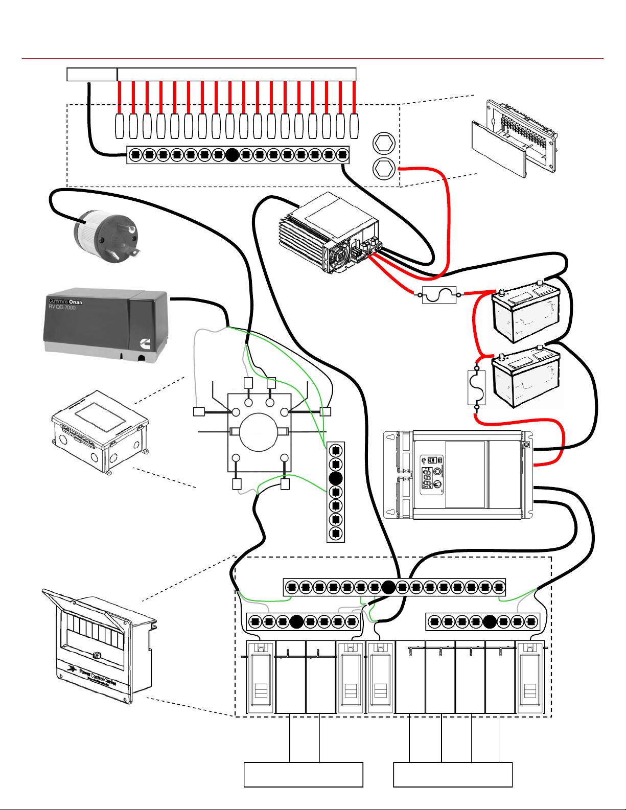
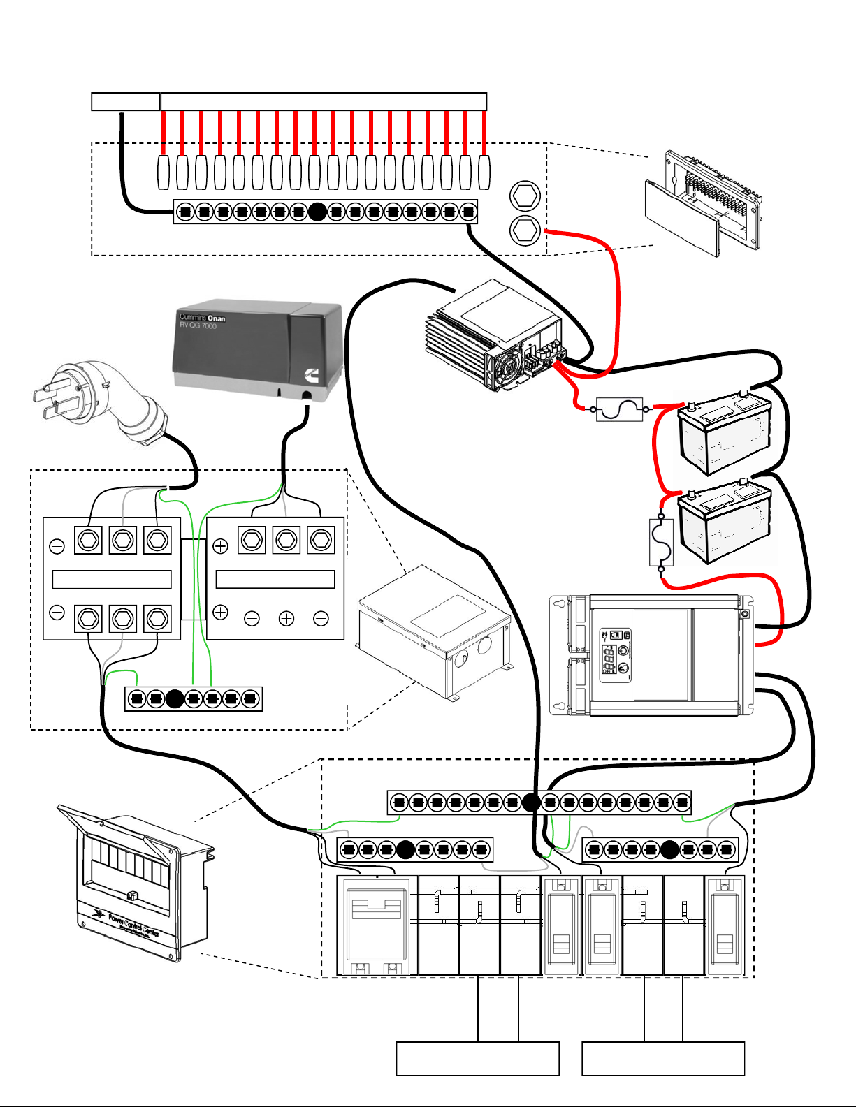
Integrated Automatic Transfer Switch
Built into the PD1600 Series Inverter is an automatic transfer switch
that engages whenever power is detected at the AC input port. In
recreational vehicles this is often used to switch over to shore or gen-
erator power when it is available, reserving the battery power for
later use. The transfer switch transition times are fast enough that
transitioning from one source to another will not impede operation
for most electrical loads.
Reverse Battery Protection
Reverse battery protection has been added to the inverter to protect
the equipment in the event that the positive and negative terminals of
the battery are incorrectly connected to the inverter. Unlike some
other inverters on the market, there is not a time delay associated
with the reverse battery protection. In the event that the inverter is
reverse wired it will not turn on.
Over-Load Protection
In order to protect the inverter from over-load conditions the power
draw is continually measured and should it exceed the rated output
power the inverter will automatically shutdown and display the error
code corresponding to an over-load error. This is a required feature
in all UL safety certified inverters.
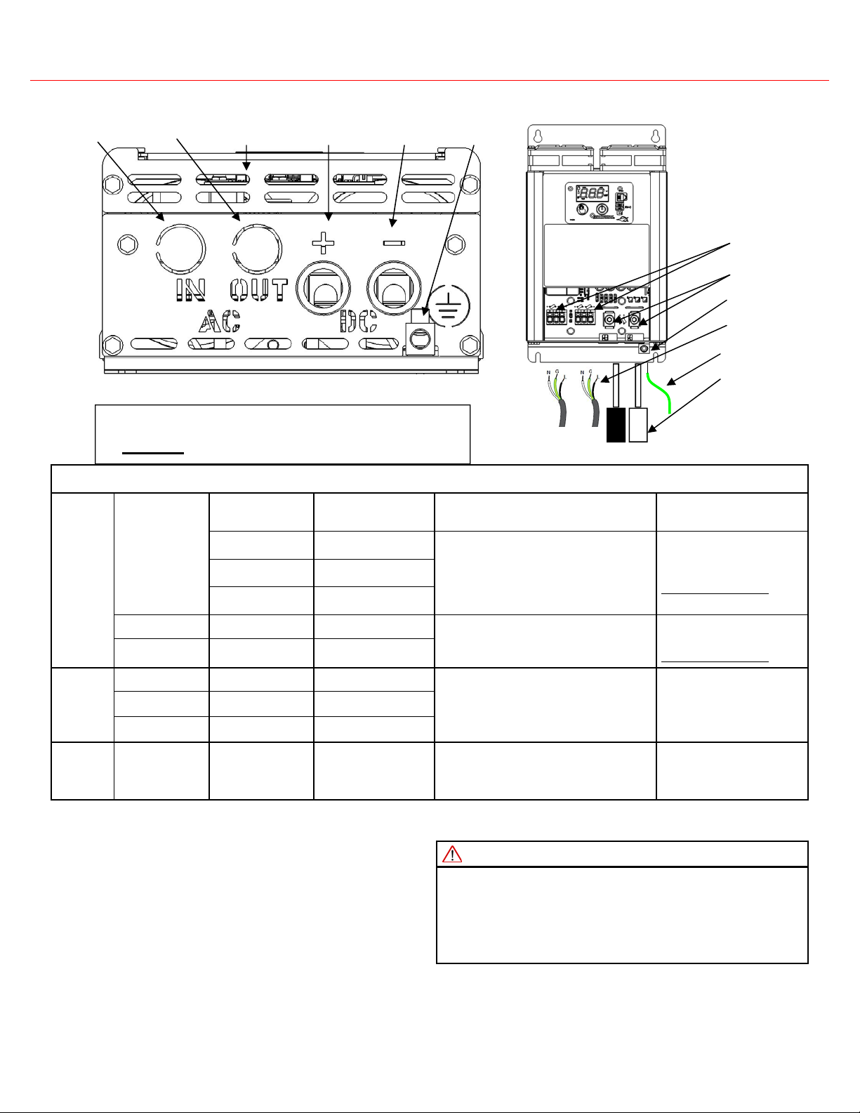
Easy Installation
When designing the PD1600 Series Inverter special attention was
paid to making it easy to install. The AC connection points are color
co-ordinate push-in terminals. When hard-wiring your new inverter
the installer can pull out the knockouts by hand, insert the Romex
cable, then push each conductor into place. The DC connections are
made directly to lugs instead of using large, expensive ring terminals.
The only tool required is a 5/32” hex key.
Short Circuit Protection
In any power system, a sustained short circuit can cause hazardous
conditions potentially resulting in over-heating and fire. To avoid
these conditions the inverter has been designed with short circuit
protection. It will detect any large current spikes caused by a short
circuit and shutdown immediately to avoid damaging the inverter and
output wiring.
2X Peak Power Rating
When starting inductive loads like compressors (found in common
household refrigerators) there is a large surge in power draw during
the initial startup. To supply this initial start up power the PD1600
Series Inverter has been designed to supply a peak power that is 2X
its rated power.
Under/Over Voltage Protection
To protect both the inverter and the battery bank the PD1600 Series In-
verter has been designed with integral under voltage and over voltage
protection. These voltage limits are designed to operate with a Lead-
Acid battery bank without damaging the batteries. The inverter may also
be used with a 12V lithium ion battery pack (LiFePO4) with a properly
configured BMS. See Specifications on page 16 for voltage limits.
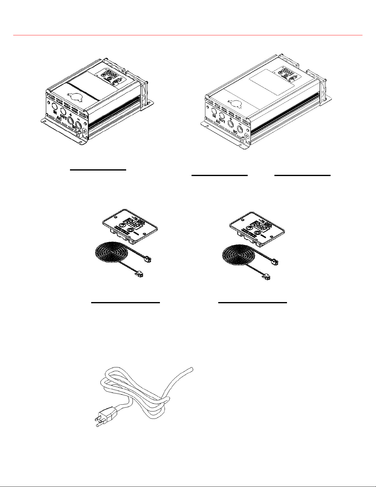
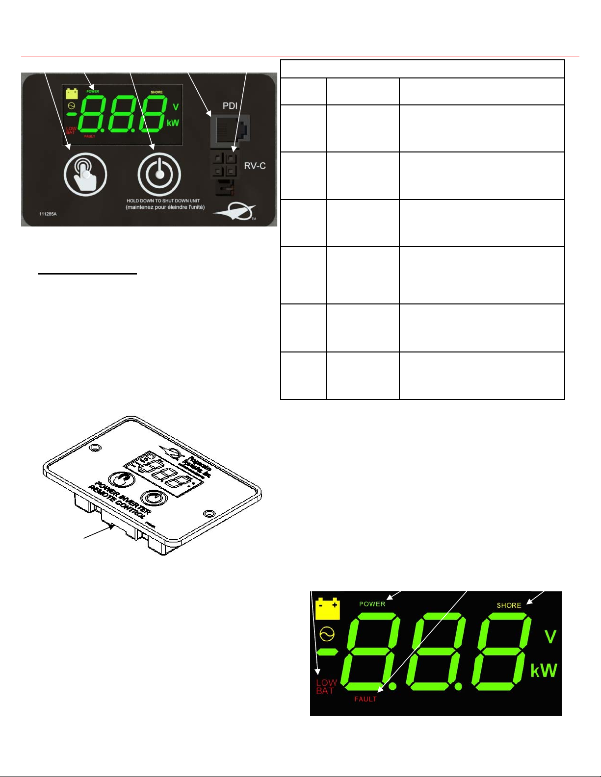
Fully Functional Remote Display (Optional)
When purchasing your inverter an optional addition is the remote
display. The PD1600 Series Inverter has an optional remote display
that is fully functional at up to 50 feet away. This includes turning on
and off the inverter and monitoring battery voltage and power con-
sumption.
Hardwired AC Output
The PD1600 Series Inverter is designed to be being used with a hard-
wired output. If a GFCI output on the inverter is required in your
application investigate the PD1600 Series Inverters offered by Pro-
gressive Dynamics.
Over Temperature Protection
A required feature for all UL safety certified inverters, over tempera-
ture protection is designed into every PD1600 Series inverter. When
the internal temperature of the inverter gets too high due to poor ven-
tilation or high ambient temperature the inverter will shutdown. The
output will automatically turn back on when the internal temperature
returns to safe operating temperatures.
Thermally-Controlled Variable Speed Fan
Using technology that is found in all Progressive Dynamics Convert-
ers, the PD1600 Series Inverter employs a thermally-controlled vari-
able speed fan. This fan will only turn on when the inverter is operat-
ing at a warmer than normal temperatures. Furthermore, when it does
turn on, the speed of the fan is smoothly controlled to only run as fast
as necessary to keep the inverter within safe operating temperatures.
This is designed to minimize disruptive audible noise
Pure Sine Wave Output
The output of the PD1600 Series inverter is a 120 VAC, 60 Hz, pure
sine wave. Unlike a modified sine wave, a pure sine wave is ideally
suited to drive all types of loads including refrigerators, motors,
power tools, and common household electronics.
Automatic Restart After DC Disconnect
The PD1600 Series Inverter will detect when the battery input con-
nections have been removed. When the DC disconnect switch is re-
engaged the inverter will automatically restart. Similar to a DC dis-
connect switch, this automatic restart also kicks in when the user
replaces the batteries. To avoid an automatic restart, simply turn off
the inverter prior to disconnecting the batteries.
Key Features
Neutral Bonding
In an RV the neutral should be tied to ground at the source of the
power. To safely accomplish this the PD1600 Series inverter ties the
neutral to ground only if the inverter is supplying the power. When
the transfer switch is engaged to pass AC Input power, the ground
connection is passed from AC input to AC output with the assump-
tion that the neutral is properly grounded wherever the power is be-
ing generated (generator or campground electrical post).

6
The PD1600 Series Inverter in a 30A RV Power System
MAIN NEUTRAL SUB NEUTRAL
12V BATTERY
BANK
PD9200 SERIES
CONVERTER
PD60 SERIES
DC DISTRIBUTION PANEL
MAIN SUB
PD51 SERIES
TRANSFER SWITCH
PD55 SERIES
AC DISTRIBUTION PANEL
GROUND
GROUND
TO DC LOADS DC GROUND
GROUND
TO AC LOADS (HOT)
(SHORE/GENERATOR ONLY)
30A 20A
TO AC LOADS (HOT)
(SHORE/GENERATOR/INVERTER)
15A 20A
GENERATOR
SHORE CONNECTION
PD1600 SERIES
INVERTER
AC IN
AC OUT
DC+
DC-
SHORE
NEU
PANEL
HOT
PANEL
NEU
GEN
NEU GEN
HOT
NOTE:
REFER TO WIRING DIAGRAM INCLUDED
WITH PD51 SERIES TRANSFER SWITCH
SHORE
HOT

7
The PD1600 Series Inverter in a 50A RV Power System
PD52 SERIES
TRANSFER SWITCH
MAIN NEUTRAL SUB NEUTRAL
12V
Battery Bank
PD60 SERIES
DC DISTRIBUTION PANEL
MAIN SUB
PD55B006
AC DISTRIBUTION PANEL
GROUND
GROUND
TO DC LOADS DC GROUND
GROUND
TO AC LOADS (HOT)
(SHORE/GENERATOR ONLY)
TO AC LOADS (HOT)
(SHORE/GENERATOR/INVERTER)
20A 20A
50A
15A
GENERATOR
PD9200
SERIES
CONVERTER
SHORE
CONNECTION
PD1600 SERIES
INVERTER
AC IN
AC OUT
DC+
DC-

8
Installation Location Requirements
The PD1600 Series Inverter should only be installed in locations that meet the following requirements:
Dry: The inverter should be installed in a compartment separated from the outside environment to avoid exposure to rain, drips, and
splashes that may damage the unit. The compartment should not be contain water or other fluids.
Cool: Air temperature of the inverter compartment should be between 4 degrees Fahrenheit and 104 degrees Fahrenheit (-20 degrees
Celsius and 40 degrees Celsius). Higher temperatures will result in a reduction of performance.
Ventilated: Do not block the opening for the fan. Do not allow the ventilation openings on the ends of the unit to be come ob-
structed. The inverter compartment should not be used for storage of any kind to maximize ventilation space. Inverter should be located
in a well ventilated compartment. Minimum compartment dimensions provide 2” of space above the inverter display and open on the
electrical connection side. Operation in high ambient temperatures require additional ventilation space.
Separated from Batteries and Flammable Materials: The PD1600 Series Inverter is not ignition protected. Do not mount
the inverter in the liquid propane gas compartment, battery compartment, or any other compartment that may contain sparks or flamma-
ble materials.
Adjacent to the Battery Compartment: It is required that the battery compartment is separate from the inverter compartment,
but the compartments should be adjacent to one another. Do not place the battery compartment directly above the inverter compartment
to avoid the potential for battery acid drips. In order to reduce cable losses and maximize system performance the DC input wires
should be kept as short as possible. See Page 10 for recommended DC input wire sizes and lengths.
Orientated Properly: It is recommended that the PD1600 series inverter is mounted horizontally (with the display facing up). The
PD1600 series inverter may also be mounted vertically (with the AC/DC access panel facing down). In vertical installation care should
be taken to avoid debris from falling into the inverter. For vertical installations it is recommended that a debris shield is installed 3
inches above the fan panel to block debris from falling into the inverter while allowing adequate air flow.
Choosing a Location For Your Inverter
WARNING: FIRE, SHOCK, OR ENERGY HAZARD
Inverter should only be installed by an electrician or a certified RV
technician.
Inverter is NOT ignition protected. Do not mount in the LP gas or bat-
tery compartments
Inverter should be mounted in a dry, well ventilated space with ade-
quate air flow
Failure to follow these instructions may result in serious injury or
death. Failure to follow these instructions may also damage the unit
and/or equipment.
RECOMMENDED GFCI’s FOR USE PD1600 SERIES INVERTER.
The PD1600 series inverters have been tested and are compatible with the following Ground-Fault-Circuit-Interrupter (GFCI) receptacles. It
is recommended that the PD1600 series inverter be used in conjunction with those listed below, for best performance. Other types may fail
to operate properly when connected to this inverter.
Recommended GFCI for use with inverter:
Leviton GFTR2, Eaton SGF20, Bestten USP-20A-20-PKB, Hongki TST20

9
Figure 5 Vertical Mounting Configuration
Mounting Instructions
1. Remove the PD1600 Series Inverter from its packaging, verify that all components are present, and record the inverter serial number in
the quick reference guide contained within.
2. Select an appropriate mounting location and orientation (See Page 8 for additional details regarding acceptable installation practices).
3. Use the inverter as a drill guide by placing it flush against the mounting surface and marking the appropriate hole locations in the
mounting surface (see Figure 4). Horizontal mounting of the PD1600 Series Inverter is recommended (see Figure 6), although it can be
mounted in a vertical position that provides unobstructed ventilation to the fan and vent holes.
4. If mounting vertically, mount the PD1600 Series Inverter that the wiring compartment is facing down (see Figure 5). This will ensure
that the display will be oriented correctly. It is best to ensure that PD1600 series inverter is placed in an area that keep dust & debris
from entering the fan area. Debris may cause unexpected performance issues in your inverter.
5. Pilot-drill the mounting holes in the marked locations
6. Secure the PD1600 Series Inverter firmly to the mounting surface using standard fasteners
Figure 6 Horizontal Mounting Configuration Figure 7 Inverter Mounting Hole Pattern
Debris Shield (recommended)
WARNING: FIRE, SHOCK, AND ENERGY HAZARD
Inverter should only be installed by an electrician or a certified RV
technician.
Inverter is NOT ignition protected. Do not mount in the LP gas or bat-
tery compartments
Inverter should be mounted in a dry, well ventilated space with ade-
quate air flow
Failure to follow these instructions may result in serious injury or
death. Failure to follow these instructions may also damage the unit
and/or equipment.
Wiring Access Panel
/PD1618

10
Electrical Connection Instructions
ELECTRICAL CONNECTION INFORMATION
DC
WIRING
PD1610(1kW)
WIRE LENGTH MIN. WIRE SIZE STRIP LENGTH CONNECTION INFO
0-5 ft. #2 AWG
Strip 3/4” (19 mm) insulation from each
cable prior to installation. Do not leave
excess copper exposed.
Tighten lugs to a torque of
100 in-lbs (11.3 N-m).
Do not over tighten.
5-10 ft. #1 AWG
10-15 ft. #1/0 AWG
PD1618(1.8kW) 0-10 ft. #2/0 AWG Strip 3/4” (19 mm) insulation from each
cable prior to installation. Do not leave
excess copper exposed.
Tighten lugs to a torque of
200 in-lbs (22.6 N-m).
Do not over tighten.
PD1620(2kW) 0-10 ft. #2/0 AWG
PD1610(1kW) 0-100 ft. #14 AWG Solid Strip 0.6” (15 mm) insulation from each
wire prior to installation. Do not leave
excess copper exposed.
Standard 3/8” trade strain
relief . No torque wrench
required
PD1618(1.8kW) 0-100 ft. #14 AWG Solid
PD1620(2kW) 0-100 ft. #12 AWG Solid
GND
WIRING PD1600 Series Any #8 AWG
Strip 0.5” (13 mm) insulation from each
wire prior to installation. Do not leave
excess copper exposed.
Torque ground lug to 30-
50 in-lbs.
AC
WIRING
NOTE: To ensure optimum performance all input wires should be as short as possible. Failure to meet minimum recommended wire
size will result in reduced performance
WARNING: FIRE, SHOCK, AND ENERGY HAZARD
Make sure wiring is disconnected from all electrical sources before
handling. All wiring must be done in accordance with local and na-
tional electrical wiring codes.
Failure to follow these instructions may result in serious injury or
death.
Electrical Connection Instructions
1. Ensure all power sources are disconnected from the inverter
2. Remove the Wiring Cover
3. Remove AC Input knockouts and AC Output knockouts
4. Install 3/8” strain relief in AC Input and AC Output ports
5. Connect AC Out terminal block (Ground, Neutral, and Line)
6. Connect AC In terminal block (Ground, Neutral, and Line)
7. Tighten strain relief (if applicable)
8. Connect DC terminals (positive and negative) to battery with properly sized wires using a 5/32” hex key
9. When connecting DC wires a small spark may occur. This is normal charging of the inverter’s internal capacitors
10. Provide external strain relief for DC wires
11. Connect equipment ground stud to a grounding point (typically the vehicle’s chassis ) using a 5/32” hex key
12. Re-install the Wiring Cover
Figure 9 Electrical Connections Top View
Figure 8 Electrical Connections Side View
PD1600 series Inverters are compatible with
BOTH Lithium and Lead Acid batteries.
AC Input Wiring
Cover
AC Output Negative DC
Connection
Positive DC
Connection
Equipment
Ground
AC Wiring
DC Wiring
DC Lugs
Ground Lug
AC Terminal
Blocks
Ground Wiring

11
Types of AC Strain Reliefs
Push-In Style
The PD1600 Series Inverter includes knockouts for use with a standard 3/8” trade size strain relief. Use of a strain relief is required when
hard wiring your inverter. Neglecting to use a strain relief may cause undue stress and fatigue to the wiring connections on your unit. PDI
lists examples of some commonly utilized types of strain relief. Strain reliefs are not provided with purchase of the inverter, and must be
provided by installer at the time of installation.
Halex #27510 or equivalent
3/8” trade size push–in connector-
Material: Plastic
Installation Instructions
1. Insert strain relief into 3/8” trade size opening
2. Push wire into slotted opening the desired distance
3. Push stripped wires into terminals blocks
4. Install wiring into terminal blocks
Metal Clamp Style
Halex #20570 or equivalent
3/8” trade size clamp combination connector
Material: Zinc plated metal
Installation Instructions
1. Insert strain relief into 3/8” trade size opening
2. Slide wire through central opening
3. Push stripped wires into terminals blocks
4. Tighten the strain relief using screws on the side
The type of 3/8” trade size strain relief used is ultimately at the discretion of the installer. PDI can only recommend
types of strain relief for end use, and is not responsible for any misuse or absence of strain relief at installation.
Plastic Clamp Style
Halex #27515 or equivalent
3/8” trade size clamp combination connector
Material: Plastic
Installation Instructions
1. Insert strain relief into 3/8” trade size opening
2. Slide wire through central opening
3. Push stripped wires into terminals blocks
4. Tighten the strain relief by sliding retention clip into the slot
Figure 10 Recommend Strain Relief

12
Figure 14 Display Indicators
Display Interface
Error
Code
Condition Description
E-1
Low battery volt-
age detected
Input voltage has dropped beneath 10.5V for
several seconds. The PD1600 Series inverter
will automatically restart when the input
voltage reaches 12.0V.
E-2
High battery volt-
age shutdown
Input voltage has surpassed 15.5V. The
PD1600 Series inverter will automatically
restart when the input voltage falls below
15.0V.
E-3
AC output over-
load shutdown
Output power has surpassed the continuous
power limit or the peak power limit. The
PD1600 Series inverter will not automati-
cally restart. A manual restart is necessary
E-4
Over-temperature
shutdown
Internal temperature of the inverter has ex-
ceeded its safe operating limit. The PD1600
Series inverter will automatically restart
when internal temperatures return to safe
operating conditions.
ERROR CODES
E-5
Internal Error An internal error has been detected. The
PD1600 Series inverter will not automati-
cally restart. A manual restart is necessary
E-6
Short Circuit A short circuit has been detected on the AC
output of the inverter. The inverter will not
restart. A manual restart is necessary.
Display Features
Power Button: Press to turn on; hold to turn off
Select Button: Cycles between display states:
Input Voltage, Output Voltage, Output
Power, Sleep, Error Code (if applicable)
Power Indicator: Lights up green when the inverter is on
Fault Indicator: Flashes red when an error has occurred
Shore Indicator: Lights up yellow when AC input is detected
Low Bat Warning Indicator: Lights up red when the battery
is nearing the end of its charge
Sleep: Lights automatically dim after 30 seconds
Remote port for externally mounted display
Figure 13 Error Code Descriptions
Figure 12 PD1601 Remote Display
Rear Remote Connection
NOTE: For troubleshooting error codes, consult page 14
NOTE: Remote display operates exactly the same as the dis-
play mounted to the inverter
Power Indicator Shore Power Indicator Low Bat Warning Indicator Fault Indicator
Figure 11 Display Panel
Select Button Display Power Button PDI Comm Port RV-C Comm Port

13
Display Operation
Figure 15 Display States
DC Input Voltage
Battery indicator is illuminated
Volts indicator is illuminated
DC Input Voltage measurement is always available
DC Input Voltage measurement is the default display state on start up
AC Output Voltage
AC indicator is illuminated
Volts indicator is illuminated
AC Output Voltage measurement is available only when the inverter is
supplying power (not when the inverter is in shore power mode)
AC Output Power
AC indicator is illuminated
kW indicator is illuminated
AC Output Power measurement is available only when the inverter is sup-
plying power (not when the inverter is in shore power mode)
Sleep
Only indicators that may be illuminated are: Power, Shore, Fault, and Low
Battery
Indicators in sleep mode will be noticeably dimmer than in any other state
The PD1600 Series Inverter display automatically enters sleep mode when
neither of the control buttons have been pressed for 30 seconds
The inverter will automatically exit sleep mode when any error occurs or
shore power is detected
To manually exit sleep mode press either button. Pressing the power button
will not turn off the inverter; it must be held for 5 seconds to power down.
Error
Error code display is only available if the inverter is currently in an error
state.
See Figure 13 for error code descriptions
See page 14 for troubleshooting guide if error code persists
NOTE: To cycle through the display states simply press the select button. Display states cycle in order as listed on this page. The display
will skip un-available display states (see display state descriptions above for additional details).

14
For further assistance contact :
PDI Service Department
service@progressivedyn.com
Troubleshooting
Troubleshooting Guide
Symptom Corrective Actions
PD1600 Series In-
verter has a flashing
fault light
The inverter has detected a fault condition. 30 Seconds after the fault condition is detected the display enters sleep mode.
Press the select button to view the error code. Press the select button again to view the battery voltage. Proceed to the
correct troubleshooting action below.
E-1 is displayed
The input voltage fell below 10.5 VDC. Inverter will automatically restart when DC Input voltage is increased to 12.0VDC
Re-charge batteries to at least 12.0VDC.
Ensure all DC input connections are tightened
Inverter is turning on
and off. E-1 is dis-
played when it is off
Likely, the batteries are nearly fully discharged. When a heavy load is being drawn from a battery the battery voltage will droop
causing an under voltage error. Then with the inverter turned off the battery voltage will slowly drift back up because there is
no load on the batteries. If the battery voltage drifts back up to 12.0VDC the inverter will turn back on. This cycle may repeat
several times. This behavior will be seen more often with batteries nearing the end of life.
Re-charge batteries to at least 12.0VDC.
Ensure all DC input connections are tightened
Make sure DC input wire size and length comply with minimum wire size diameter.
Replace batteries
Batteries are fully
charged. Inverter dis-
plays E-1 immediately
after it is turned on
The batteries may be fully charged, but if the battery voltage is not properly connected to the DC Input terminals of the inverter
a low battery fault may be falsely triggered.
Ensure all DC input connections are tightened
Make sure DC input wire size and length comply with Figure 15
E-2 is displayed
The input voltage has exceeded 15.5VDC. Inverter will automatically restart when DC Input voltage is decreased to 15.0VDC
Turn off the inverter by holding down the power button. Locate DC source and verify it is properly connected for 12VDC
operation
E-3 is displayed
An over-load condition has been detected. This can be excessive power or a peak power that exceed 2X rated power. A manual
restart is required after the over-load issue has been resolved.
Check output wiring for a short circuit.
Determine what loads are connected to the output of the inverter. Remove un-necessary loads until power is below maxi-
mum rated power.
E-4 is displayed
An over temperature condition has occurred. The inverter will automatically restart when the internal temperature falls to safe
operating conditions.
Ensure that debris hasn’t fallen into the fan opening blocking its operation
Remove items surrounding the inverter to ensure adequate air flow.
Move inverter to a well ventilated space.
Lower ambient air temperature to room temperature.
Inverter is turning on
and off. E-4 is dis-
played when it is off
An over temperature condition has occurred. The inverter will automatically restart when the internal temperature falls to safe
operating conditions.
Ensure that debris hasn’t fallen into the fan opening blocking its operation
Remove items surrounding the inverter to ensure adequate air flow.
Move inverter to a well ventilated space.
Lower ambient air temperature to room temperature.
Inverter is making a
buzzing sound
A buzzing sound may be produced during large surges in output power. This will most commonly be observed on some refrig-
erators when the compressor is starting up. This buzzing sound is normal and should not last for more than 2 seconds.
WARNING: FIRE, SHOCK, OR ENERGY HAZARD
DO NOT disassemble the inverter. It does not contain any user service-
able parts. Attempting to service the unit yourself could result in an
electrical shock or burn.
Failure to follow these instructions may result in serious injury or
death.

15
Troubleshooting
Troubleshooting Guide
Symptom Corrective Actions
E-5 is displayed
During startup the inverter draws a small amount of current to charge the input capacitors. If that current exceeds a normal
range the inverter shuts down and reports an internal error. This is can be indicative of bad input wiring or an internal failure.
Ensure all DC input connections are tightened
Make sure DC input wire size and length comply with Figure 15
E-6 is displayed
A short circuit has been detected on the AC output of the inverter.
Check the AC wiring to make sure that wires aren’t touching each other
Check each AC load for failure
Determine surge requirements for AC loads. Motorized loads may draw peak power greater than the peak power rating
Inverter is off. Noth-
ing happens with
power button is
pressed
Likely, DC Input power is not being properly applied to the DC input terminals.
Ensure all DC input connections are tightened
Ensure that all any external DC disconnect switches are in the on position
Ensure that the DC input wires are connected to positive and negative correctly (not reversed)
If using the remote display panel, make sure that it is connected to the inverter using the provided 25’ cable.
Inverter turned off for
seemingly no reason
Something has interrupted the communication between the display and the inverter.
Ensure that the equipment ground wire is properly secured to the equipment ground lug
For Further Assistance Contact:
PDI Service Department:
WARNING: FIRE, SHOCK, OR ENERGY HAZARD
DO NOT disassemble the inverter. It does not contain any user service-
able parts. Attempting to service the unit yourself could result in an
electrical shock or burn.
Failure to follow these instructions may result in serious injury or
death.
*All ratings at 25 °C unless otherwise listed
SPECIFICATIONS
PHYSICAL SPECIFICATIONS TRANSFER SWITCH
PD1610 PD1618 PD1620 PD1610 PD1618 PD1620
Dimensions
L:11.2”(284mm)
W:6.7”(170mm)
H:4.0”(101mm)
L:15.0”(381mm)
W:7.9”(200mm)
H:4.0”(101mm)
L:15.0”(381mm)
W:7.9”(200mm)
H:4.0” (101mm)
Transfer Voltage 95 - 135 VAC
Transfer Time < 50 msec
Net Weight 7 lbs (3.2 kg) 11 lbs (5.0 kg) 11 lbs (5.0 kg) Pass Through
Ampacity 20 AAC
AC OUTPUT DC INPUT
PD1610 PD1618 PD1620 PD1610 PD1618 PD1620
Waveform Pure Sine Wave Nominal Voltage 12.0 VDC
Output
Voltage 120 VAC Under-Voltage
Shutdown 10.5 VDC
Max Power
(Cont) 1000W 1800W 2000W Under-Voltage
Restart 12.0 VDC
Max Power
(Peak) 2000W 3600W 4000W Over-Voltage
Shutdown 15.5 VDC
Frequency 60 Hz Over-Voltage
Restart 15.0 VDC
Peak
Efficiency 90% Max Current @
max load 100 ADC 180 ADC 200 ADC

16
RV-C Connectivity Specification
Figure 16 RV-C Comm Port
CAN-H CAN-L NC NC RV-C Introduction
The PD1600 Series Inverter was designed to include RV-C communi-
cations capability. RV-C is an industry developed communications
protocol that is used in many RV multiplexing systems. The PD1600
Series Inverters were released with limited functionality to turn on/off
the inverter and report back basic operating parameters. Additional
functionality will be added to the PD1600 Series Inverters as required
to operate with modern RV multiplexing systems. See chart below for
the current list of compatible Data Groups.
PD1600 Series Inverter RV-C Compatible Data Groups
Data Group Periodic Send Description
Product ID n/a When requested the inverter responds with the make and model
“Progressive Dynamics * PD1600 Series vX.XX”
DM RV 4 seconds Provides information on Service Points in the event of a fault
Inverter AC Output Page 1 0.1 seconds Provides information on AC output frequency and voltage
Inverter AC Output Page 2 0.1 seconds Provides information on AC bypass ampacity
Inverter AC Output Page 3 0.1 seconds Provides information on AC waveform and AC output power
Inverter AC Output Page 4 0.1 seconds Data Group not yet implemented
Inverter Status 0.5 seconds Provides inverter status: Disabled, Inverter, AC Pass-through
DC Status 4 seconds Provides information on DC input voltage
Inverter Command n/a Accepts command to turn on/off the inverter
Address Claimed n/a When prompted the inverter indicates that it has a static address com-
patible with RV-C.
Other manuals for PD1600 Series
1
This manual suits for next models
4
Table of contents
Other Progressive Dynamics Inverter manuals

Progressive Dynamics
Progressive Dynamics PD1200 Series User manual

Progressive Dynamics
Progressive Dynamics PD1600 Series User manual

Progressive Dynamics
Progressive Dynamics PD1610 User manual

Progressive Dynamics
Progressive Dynamics PD1210SV Operating instructions

Progressive Dynamics
Progressive Dynamics PD1618 Series Operating instructions

Progressive Dynamics
Progressive Dynamics PD1200 Series Operating instructions