WINDY NATION VertaMax Series User manual

windynation
VertaMax
Power Inverter Series
User’s Manual
Modified Sine Wave
Pure Sine Wave
PIN-1200-12M
PIN-1000-12P

windynation
Page 2 of 16
VertaMax User Manual
Revision 2
Table of Contents
1Introduction .................................................................................................................3
1.1 Features ..........................................................................................................3
1.2 Safety Information............................................................................................4
1.3 Specifications...................................................................................................4
1.3.1 Electrical Specifications........................................................................................ 4
1.3.2 Physical Specifications......................................................................................... 4
2Installation ...................................................................................................................4
2.1 Electrostatic (ESD) Precautions .......................................................................5
2.2 Mounting..........................................................................................................5
2.3 Grounding........................................................................................................5
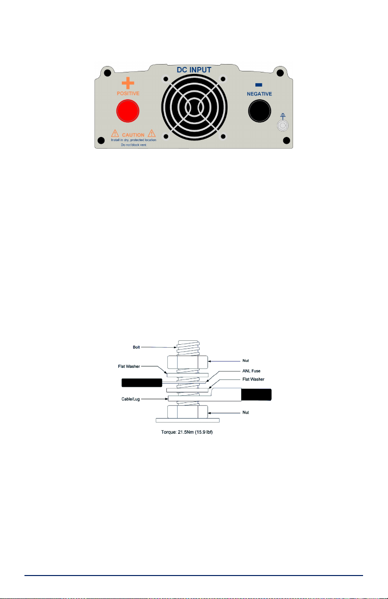
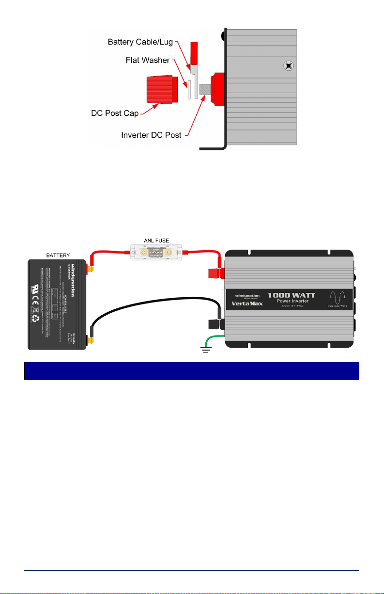
2.4 Connections.....................................................................................................5
3Operation ....................................................................................................................7
3.1 Power ..............................................................................................................7
3.1.1 Power ON ............................................................................................................7
3.1.2 Power OFF .......................................................................................................... 8
3.1.3 Remote ON/OFF (optional) .................................................................................. 8
3.1.4 USB Power Port* ................................................................................................. 8
3.2 Meter Readings ...............................................................................................9
3.3 Protection – Alarms..........................................................................................9
3.3.1 Over Input Voltage ...............................................................................................9
3.3.2 Low Input Voltage ................................................................................................ 9
3.3.3 Power Overload ...................................................................................................9
3.3.4 Over Heating........................................................................................................9
3.3.5 Short Circuit ....................................................................................................... 10
3.3.6 Functional Matrix................................................................................................ 10
4Application.................................................................................................................10
4.1 Power Consumption.......................................................................................10
4.2 Typical Power Consumption ..........................................................................10
4.3 Wire Gauge Reference ..................................................................................11
4.3.1 Ampacity Table ..................................................................................................11
4.3.2 Wire Thickness ..................................................................................................11
4.4 Batteries ........................................................................................................11
4.4.1 Battery Life......................................................................................................... 11
4.4.2 Battery State of Charge (SOC)........................................................................... 12
4.4.3 Actual Battery Current Draw............................................................................... 12
4.4.4 Battery Capacity................................................................................................. 12
5Troubleshooting And Support ....................................................................................13
5.1 Maintenance & Care ......................................................................................13
5.2 Troubleshooting .............................................................................................13
5.3 Support ..........................................................................................................14
5.4 Warranty........................................................................................................14
5.4.1 Restrictions ........................................................................................................ 14
5.4.2 Warranty Claims & Return Procedures............................................................... 15
5.4.3 Disclaimer ..........................................................................................................15
5.4.4 Limitation of Liability........................................................................................... 16

windynation
Revision 2
VertaMax User Manual
Page 3 of 16
1 INTRODUCTION
The VertaMax Power Inverter is a highly reliable product that uses advanced technologies for
high performance and stability. The VertaMax efficiently converts DC power from your vehicle,
boat, or directly from a dedicated 12V DC battery, into 115V AC power that is commonly used in
a wide variety of household AC items, such as computers, mobile phone chargers, radio, TV etc.
The Inverter may be used for many different applications including Solar (PV) battery systems,
Wind Turbine battery systems, Recreational Vehicles, Boats, etc.
The VertaMax has many features that you would expect in very high-end inverters as well as all
the safety features that would be desired to protect your equipment. It is offered in both Pure Sine
Wave and Modified Sine Wave Versions. Both versions will provide AC power to appliances,
where the modified sine wave is considered an affordable, all-purpose inverter and the pure sine
wave is considered a more expensive higher quality inverter, where the power being produced
would be equal to, or even better than, the power from the electrical grid.
Modified sine wave power is adequate for simple electronics, but may damage more complex
ones. They are ideal for powering less sensitive appliances like phone chargers, heaters and air
conditioners. Modified inverters are best suited for resistive loads which don't have a startup
surge.
Pure sine wave inverters use more sophisticated technology to protect sensitive electronics such
as televisions, laptops, digital microwaves, refrigerators, and inductive type loads. Appliances
which may not function properly, or which may be permanently damaged, should be powered with
a pure sine wave inverter.
Please read this manual carefully before installing or using the inverter and keep it for future
reference.
1.1 FEATURES
Microprocessor Based PWM (Pulse Width Modulation) Operation
Three AC Receptacles
USB Charging Port
Soft Start
Digital Display Voltage and Power Meter
Power On/OFF Switch and LED indicator
Remote On/Off Capability
Automatic Overload Protection
Low Voltage Shutdown Battery Protection
Short Circuit Protection
High Temperature Protection
Fault Indication
Load and Thermally Activated Cooling Fan
1
DC Positive (+) Input
7
USB Charging Port
2
Cooling Fan
8
Power LED
3
DC Negative (-) Input
9
Digital Display Meter
4
Grounding Terminal
10
Fault LED
5
AC Outlets [x3]
11
ON/OFF Switch
6
Remote Switch Port1
12
Digital Display Select Switch

windynation
Page 4 of 16
VertaMax User Manual
Revision 2
1Optional Remote Cable required [PN: PIN-RMPS-01]
1.2 SAFETY INFORMATION
Please read the installation and operating instructions carefully prior to use. Pay special attention
to the IMPORTANT and WARNING statements in the manual.
WARNING:
The VertaMax produces the same potentially lethal AC power as normal household outlets. It is
suggested that you treat it with the same precautions as a normal 115 VAC outlet.
Do not operate the VertaMax near flammable fumes or gases, such as in the cabin of a gasoline
powerboat, or near propane tanks.
Never work or service the AC wiring without disconnecting the DC Input connections.
Do not connect or disconnect batteries while the Inverter is operating from the battery supply.
Dangerous arcing may result.
Although the inverter has over-voltage protection, the input voltage should never exceed 15V.
Input voltages of 16VDC or more will permanently damage the inverter.
Due to high voltages inside the inverter, the inverter should never be opened when in use.
1.3 SPECIFICATIONS
1.3.1 Electrical Specifications
Parameter
PIN-1200-12M
PIN-1000-12P
Continuous Rated Power
1200 Watts
1000 Watts
Peak Surge Power
2400 Watts
2000 Watts
Standby Current
<0.50A
<0.50A
Output Waveform
Modified Sine Wave
Pure Sine Wave - THD <3%
Input Voltage (Nominal)
12 – 13 VDC
Input Voltage (Min – Max)
11 – 15VDC
Output Voltage (Nominal)
115VAC
Output Frequency (Nominal)
60 Hz
Low Battery Voltage Alarm
10.5 VDC (+/-0.3VDC)
Low Battery Voltage Shutdown
10.0 VDC (+/-0.3VDC)
High Battery Voltage Shutdown
16 VDC (+/-0.5VDC)
Efficiency
85-90%
1.3.2 Physical Specifications
Parameter
Specification
Dimension (L x W x H)
11.4” x 8.7” x 3.1” (290mm x 221mm x 79mm)
Unit Weight
5.7 lb. (2.6kg)
Cooling
Auto Powered Fan
Operating Temperature
0oC to 40oC
Storage Temperature
-25oC to 70oC
Operating Humidity
20 to 80% relative humidity (non-condensing)
Over Temperature Shutdown
>65oC
2 INSTALLATION
Insure all terminating connections are clean and tight to prevent arcing and overheating.
The VertaMax must be installed in an area that satisfies all of the following conditions:
1. Dry: Avoid any location where water can contact the inverter
2. Cool: Ambient air temperature between 30°F and 105°F (0°C and 40°C)

windynation
Revision 2
VertaMax User Manual
Page 5 of 16
3. Ventilated: Allow at least 6 in (150 mm) of clearance above and below and at least
1 in (25 mm) on each side for proper air flow.
4. Safe: Do not operate in a shared compartment with batteries or any flammable
substances, (e.g.: gasoline)
IMPORTANT:To avoid fire, do not cover or obstruct ventilation openings.
2.1 ELECTROSTATIC (ESD) PRECAUTIONS
All electronic circuits may be damaged by static electricity. To minimize the likelihood of
electrostatic damage, discharge yourself by touching an electrical ground (e.g.: copper pipe) prior
to handling the unit and avoid touching components on the circuit boards. The risk of electrostatic
damage is highest when relative humidity is below 40%.
2.2 MOUNTING
Mounting is optional for the VertaMax; however, the environment must be dry and protected from
water.
1. The VertaMax can be mounted on a vertical or horizontal surface. If mounted
vertically, the unit should be oriented such that neither end is at the top so foreign
material cannot settle into the unit.
2. Install four user-supplied fasteners through the four inverter mounting slots and
into the mounting surface.
3. Tighten all the fasteners to ensure the inverter cannot slide in any direction.
WARNING: Do not mount on flammable surface material.
2.3 GROUNDING
The VertaMax is designed to work with grounded electrical systems by using a copper wire to
connect the grounding terminal on the VertaMax enclosure to earth ground or chassis ground.
The grounding terminal is located on the DC Input end of the inverter.
•Vehicle installations: Connect to the chassis of the vehicle.
•Boats installations: Connect to the boat’s grounding system
•Fixed land based installations: Connect to earth ground
Do not connect the system negative conductor to this terminal. NEC requires the use of an
external ground fault protection device (GFPD). The system electrical negative should be bonded
through a GFPD to earth ground at one (and only one) location. The grounding point may be
located in the solar/wind circuit or the battery circuit.
2.4 CONNECTIONS
WARNING: Electrical installations must meet local and national wiring codes, and must be
performed by a qualified electrician.
WARNING: Do not connect the inverter and another AC source (such as a generator or utility
power) to the AC wiring at the same time.
WARNING: Do not connect the inverter to an AC branch circuit that has high-power consumption
loads. It will not operate electrical appliances that consume more than the units rated watts.
WARNING: Loose connectors result in excessive voltage drop and may cause over heated wires
and melted insulation, which can lead to electrical fires.
WARNING: Reverse polarity connections (positive to negative) will blow internal fuses in the
inverter and may permanently damage the Inverter.
IMPORTANT: The NEC requires that the wires carrying the system current never exceed 80% of
the conductor’s current rating (sizing recommendations are located in Section 4).
IMPORTANT: In addition to the protection provided by the Inverter’s internal fuses, NEC requires
a UL-listed fuse in the battery’s positive DC cable as close to the battery as possible.

windynation
Page 6 of 16
VertaMax User Manual
Revision 2
1) The VertaMax has two DC terminals, one positive and one negative. Red is Positive [+] and
black is Negative [-] and has the same polarity as the battery. When connected, positive
must connect to positive (red to red), negative connect to negative (black to black).
IMPORTANT: Use a minimum of 4 AWG wire with a wire length not to exceed 4 feet*.
* For wire runs longer than 4 feet, consult the Wire Gauge Chart in Section 4.3 to safely
determine what gauge of wire will be needed.
2) Prepare cables of equal length to connect the power source to the inverter. The cables
should be as short and thick as possible to reduce the voltage drop between the power
source and the inverter as it draws current from the power source.
a) Inverter end of the cable: Terminate copper wire with a 0.3125” diameter, tin-plated
copper lug. It is recommended to cover the lug barrel with 1 inch of heat shrink tubing.
b) Power Source end of the cable: Terminated with a lug or other connector that provides
a secure, low resistance connection. For example, if the power source is a battery, the
cable must be terminated with a battery terminal that clamps to the post on the battery.
IMPORTANT: If there is an excessive voltage drop and the voltage at the inverter drops below 10
volts, the inverter will shut down.
3) Wire the positive cable(s) through user-supplied UL-listed ANL type fuse as shown below.
The fuse should be as close to the battery as possible. A 100 Amp fuse is recommended,
but the specific fuse ampere rating should be sized to allow operation of all your DC
powered equipment but cannot exceed the maximum current (amp) rating of the inverter by
more than 40%.
4) Be sure the inverter power button is in the ‘OFF’ position and the DC Power source is also
off.
5) Connect the cable end with the 0.3125” lug to the Power Input Terminals on the DC Input
end of the inverter as shown below. The red terminal is positive (+) and the black terminal is
negative (-).
Use the washer and DC Post Caps (provided) as shown below. Fully tighten until the Cable
Lug is secured.

windynation
Revision 2
VertaMax User Manual
Page 7 of 16
IMPORTANT: When fully tightened, the Cable Lug should not be able to rotate around the
Inverter connection post. Check and tighten the end caps periodically as they can become
loose from vibrations or thermal cycling.
6) Connect cables to the power source:
a) Connect the cable from the Negative (Black) Terminal of inverter to the Negative
Terminal of the power source; ensure a secure connection.
b) Connect the cable from the Positive (Red) Terminal of the inverter to the Positive
Terminal of the power source (the battery’s main fuse or the battery selector switch, if
you are using one); ensure a secure connection.
3 OPERATION
IMPORTANT: The inverter must be rated at more power that the intended electrical appliances to
be used. A 20% margin is recommended
3.1 POWER
The VertaMax features a Soft Start to handle the power surge that is created when some
appliances are turned on. This feature helps protect both the appliance and the inverter from
excessive power draws and surges.
When the power switch is turned on, the VertaMax Soft Start will smoothly bring up the AC
power. The Soft Start circuitry also activates under excessive loads and short circuits, to quickly
turn off power to protect the device and the inverter. Soft Start will attempt to smoothly bring up
the AC power, unless it detects an excessive load.
3.1.1 Power ON
Ensure the VertaMax is properly installed and connected as shown in Section 2 and ensure the
DC Power Source is ON (if switched).
From the AC Output end of the inverter, switch the rocker power switch to the ON position. The
green power indicator will light and the VertaMax will now deliver AC power to the outlet(s) on the
AC Output end of the inverter.

windynation
Page 8 of 16
VertaMax User Manual
Revision 2
Plug the AC product(s) you wish to operate into the AC outlet(s) and switch them on, one at a
time.
IMPORTANT: Do not turn on all AC products at the same time and turn on the larger power
product first.
IMPORTANT: In the ON position, even if no loads are connected, there is a low current draw
(<0.5A).
3.1.2 Power OFF
From the AC Output end of the inverter, switch the rocker power switch to the OFF position to
shut down the Inverter completely, preventing it from drawing power from the batteries. The green
power indicator will go out.
This will also “reset” the unit if it shuts down due to low battery or overload.
3.1.3 Remote ON/OFF (optional)
The VertaMax is equipped with a remote port, that when used with the optional Remote Power
Switch1will allow you to turn the power inverter ON or OFF remotely when the inverter is installed
in an out of reach location.
1Remote Power Switch: Part Number PIN-RMPS-01 (purchased separate) is a 5 meter corded
remote control available from Windy Nation.
To remotely control the power function of the inverter, switch the rocker power switch (on the
inverter) down to the OFF position, essentially shutting down the Inverter. From the Remote
Control press the “ON” button to turn the inverter on and the “OFF” button to turn the power off.
IMPORTANT: Although the main power rocker switch will be in the OFF position, the green
power indicator will work as normal operation and will light when the VertaMax is remotely “ON”.
3.1.4 USB Power Port*
The VertaMax is equipped with a USB charging port, that will deliver 5 volts at a maximum
current of 2.1 amps. This port can be used to conveniently charge all standard USB accessory
items; eg: cell phones, portable speakers, etc.

windynation
Revision 2
VertaMax User Manual
Page 9 of 16
3.2 METER READINGS
The VertaMax is equipped with a digital meter on the AC Output End of the unit. The meter will
provide one of the following measurements, depending on the switch selection:
1) WATTS: AC output power; shown in Watts
2) VOLTS: DC input voltage of the batteries; shown in Volts DC
IMPORTANT: The Watt-Meter will read “00” until a minimum of 1 amp is drawn; i.e.: 120 watts
3.3 PROTECTION –ALARMS
The VertaMax has several protection features to protect itself as well as your electrical system.
3.3.1 Over Input Voltage
When the DC INPUT power voltage exceeds 16V DC, the alarm will beep three (3x) times and
the FAULT LED will blink Red.
The inverter will automatically shut down to protect itself from excessive input voltage.
IMPORTANT: Although the inverter incorporates protection against over-voltage, it is still
possible to damage the unit when the input voltage exceeds 15V DC.
3.3.2 Low Input Voltage
As a battery is used, its voltage begins to decrease. When the inverter senses that the voltage at
its DC input has dropped to 10.5V ± 0.3 DC, an audible alarm will sound and operation will
remain normal. When this happens, it is important to remove or shut down computers or other
sensitive devices that may be connected to the VertaMax and recharge the battery before its
capacity drops too low. The inverter can operate while the battery is recharging.
If the audible alarm is ignored and the voltage drops to 10.0V DC, the alarm will beep three (3x)
times, the FAULT LED will blink Red, and the inverter will automatically shut down to protect the
battery from being over-discharged.
When the input voltage rises to approximately 11.4 – 11.9V DC, the inverter restores to normal
operation and the red FAULT indicator will turn off.
3.3.3 Power Overload
When the starting power exceeds the rated surge power or the AC appliances connected to the
VertaMax exceed the inverter’s power rating, the alarm will beep continually and the FAULT LED
will blink Red. The output voltage will decrease and the inverter will automatically shut down after
approx. 20 seconds.
When in over current protection mode, the inverter cannot automatically restore to normal
operation; reset to normal operation by using the manual power switch.
3.3.4 Over Heating
After continuous use the inverter case temperature will rise to ~60oC. When the inverter exceeds
a safe operating temperature, due to insufficient ventilation or an increase in ambient
temperature, the alarm will beep two (2x) times and the FAULT LED will blink Red. If the over-
temperature condition persists, the inverter will automatically shut down.
Should this occur, place the inverter in a well ventilated, dry place, with a distance of at least 7”
(20cm) from any objects. The ambient environmental temperature should not exceed 40oC.
The inverter's cooling fan(s) are temperature controlled and only activate when the inverter is
approaching an unsafe operating temperature
When the temperature drops, the inverter will automatically return to normal operation.
IMPORTANT:The cooling fan is designed to operate when the temperature increases but may
not be adequate enough to prevent overheating.

windynation
Page 10 of 16
VertaMax User Manual
Revision 2
3.3.5 Short Circuit
This inverter is equipped with multiple internal fuses. When in a short circuit state, the alarm will
beep and the FAULT LED will blink Red. The inverter will automatically shut down after three (3)
seconds.
3.3.6 Functional Matrix
Operational Mode
Power
Switch
Power
Light
Fault
Light
Audible
Alarm
Unit is off
Off
Off
Off
Off
Normal Operation
On
On
Off
Off
Low input voltage, <11V
On
On
Off
On
Low input voltage, < 10.5V
On
On
On
On
Low input voltage, < 10.0V
On
Off
On
On
High Input voltage, > 15V
On
On
On
On
High Input voltage, > 16V
On
Off
On
On
Over temperature or overload
On
Off
On
On
No 12V DC input
On
Off
Off
Off
4 APPLICATION
4.1 POWER CONSUMPTION
For each piece of equipment you will be operating from the inverter, you must determine the
battery’s reserve capacity (how long the battery can deliver a specific amount of current – in
automotive batteries, usually 25 ampere) or ampere-hour capacity (a measure of how many
amperes a battery can deliver for a specified length of time).
Example – Reserve capacity: a battery with a reserve capacity of 180 minutes can deliver 25
ampere for 180 minutes before it is completely discharged.
Example – Ampere-hour capacity: a battery with an ampere-hour capacity of 100 ampere-hours
can deliver
5 ampere for 20 hours before it is completely discharged.
To determine the battery ampere-hour capacity:
1) Determine how many Watts each piece of AC equipment (TV, light bulbs, etc)
consumes. This can normally be found on the product label. If only the current draw is
given, multiply the current draw by 115 to get the Watt consumption.
2) Estimate the time (in hours) that each piece of equipment will be running between
battery charging cycles.
3) Calculate the total Watt-Hours of energy consumption (power in Watts x operating time
in hours) using the average power consumption and the total estimated running time (in
hours). Power x Operating Time = Watt-Hours.
4) Divide the Watt-Hours by 10 to determine how many battery (12 volt) ampere-hours will
be consumed.
4.2 TYPICAL POWER CONSUMPTION
Appliance
Watts
Appliance
Watts
Stereo
200
Microwave - 1000 W
1000
Table Fan
200
AC (5,000 BTU)
700
TV
250
Computer
300
Small Refrigerator
350
Hair Dryer
1000
Hand Drill - 1/2"
600
Coffee Maker
1200
Light Bulb - 100 W
100
Blender
400

windynation
Revision 2
VertaMax User Manual
Page 11 of 16
4.3 WIRE GAUGE REFERENCE
4.3.1 Ampacity Table
Load Amperage – Power @ 12VDC
10A
120W
20A
240W
30A
360W
40A
480W
50A
600W
60A
720W
70A
840W
80A
960W
100A
1200W
120A
1440W
160A
1920W
200A
2400W
250A
3000W
Cable Length (feet)
2 16AWG
16AWG
14AWG
12AWG
10AWG
8AWG 8AWG 6AWG 4AWG 2AWG 2AWG
2/0AWG
3/0AWG
4 16AWG
16AWG
14AWG
12AWG
10AWG
8AWG 6AWG 6AWG 4AWG 2AWG 1AWG
2/0AWG
4/0AWG
6 16AWG
14AWG
12AWG
10AWG
8AWG 6AWG 6AWG 4AWG 2AWG 2AWG
1/0AWG
3/0AWG
4/0AWG
8 16AWG
14AWG
12AWG
10AWG
8AWG 6AWG 6AWG 4AWG 2AWG 2AWG
1/0AWG
3/0AWG
4/0AWG
10
16AWG
14AWG
12AWG
10AWG
8AWG 6AWG 6AWG 4AWG 2AWG 2AWG
1/0AWG
3/0AWG
4/0AWG
12
14AWG
14AWG
12AWG
10AWG
8AWG 6AWG 6AWG 4AWG 2AWG 2AWG
1/0AWG
3/0AWG
4/0AWG
16
14AWG
12AWG
12AWG
10AWG
8AWG 6AWG 6AWG 4AWG 2AWG 2AWG
1/0AWG
3/0AWG
4/0AWG
20
14AWG
12AWG
10AWG
8AWG 6AWG 6AWG 4AWG 4AWG 2AWG 2AWG
2/0AWG
4/0AWG
4/0AWG
24
12AWG
12AWG
10AWG
8AWG 6AWG 4AWG 4AWG 2AWG 1AWG 1AWG
2/0AWG
4/0AWG
4/0AWG
28
12AWG
10AWG
8AWG 8AWG 6AWG 4AWG 4AWG 2AWG 1AWG 1AWG
2/0AWG
4/0AWG
4/0AWG
33
10AWG
10AWG
8AWG 6AWG 4AWG 4AWG 4AWG 2AWG 1AWG 1AWG
2/0AWG
4/0AWG
4/0AWG
42
10AWG
8AWG 6AWG 6AWG 4AWG 4AWG 2AWG 1AWG
1/0AWG
1/0AWG
3
/0AWG
4/0AWG
NR
50
8AWG 6AWG 6AWG 4AWG 4AWG 2AWG 2AWG 1AWG
1/0AWG
1/0AWG
3
/0AWG
NR NR
NOTE: Applicable to conductors: Rated 0 through 2000 Volts with an ambient Temperature of
30°C (86°F)
4.3.2 Wire Thickness
AWG
Diameter
inches (mm)
Ohms per
1000ft
Break Force
Square mm2
16
0.051 (1.29)
4.016
75 lbs
1.30
14
0.064 (1.63)
2.525
119 lbs
2.08
12
0.081 (2.05)
1.588
197 lbs
3.30
10
0.102 (2.59)
0.999
314 lbs
5.26
8
0.129 (3.26)
0.628
480 lbs
8.30
6
0.162 (4.11)
0.395
760 lbs
13.30
4
0.204 (5.19)
0.249
1210 lbs
21.15
2
0.258 (6.54)
0.156
1930 lbs
33.62
1
0.289 (7.35)
0.124
2430 lbs
42.41
0 (1/0)
0.325 (8.25)
0.098
3060 lbs
53.49
00 (2/0)
0.365 (9.27)
0.078
3860 lbs
67.43
000 (3/0)
0.410 (10.4)
0.062
4860 lbs
85.01
0000 (4/0)
0.460 (11.68)
0.049
6120 lbs
107.22
4.4 BATTERIES
4.4.1 Battery Life
The VertaMax can draw lots of amps from your battery when operating. If you are using it for
extended periods of time, you will want to recharge occasionally to maintain the charge in the
battery. In addition, the power inverter will also draw a small current, less than 600mA, when
turned off and not operating. Therefore, it should be disconnected from your battery if it will not be

windynation
Page 12 of 16
VertaMax User Manual
Revision 2
used for more than a day. The following chart shows typical operation time for typical batteries for
various loads.
Power Usage
Current @ 12V
50A/h Battery Operating
Time
100A/h Battery
Operating Time
100 watt
9 Amps
5.5 hours
11 hours
200 watt
19 Amps
2.6 hours
5.2 hours
500 watt
47 Amps
1 hour
2 hours
*All Values are approximate
4.4.2 Battery State of Charge (SOC)
You can measure battery state of charge with a hydrometer or approximate state of charge with a
voltmeter. Using a digital voltmeter that can display tenths or hundredths of a volt, measure the
battery when it has not been charged or discharged for several hours.
For a deep-cycle battery at 77º F (25º C), use the following table:
Battery Voltage
State of Charge
12.7 – 13.0 V
100%
12.5 – 12.6 V
80%
12.3 – 12.4 V
60%
12.1 – 12.2 V
40%
11.9 – 12.0 V
20%
4.4.3 Actual Battery Current Draw
Approximate 12 volt current draw is the AC load in Watts divided by 10. Thus a 60 watt light bulb
plugged into the inverter will cause the inverter to draw approximately 6 amps (60 / 10 = 6) from
the 12 volt power supply (e.g. battery).
Batteries are rated in several different ways:
•Peak cranking amps - This has little to do with how long an inverter can supply power,
so it is not a useful number for inverter operation.
•Battery reserve capacity - This number shows how long a battery can supply a given
current, typically 25 amps, before the battery voltage reaches a low voltage. Therefore,
a battery rated at 200 minutes reserve can deliver 25 amps for 200 minutes before it is
discharged. Ampere-hour capacity - This rating indicates how many amps a battery can
deliver over a period of time, typically 20 hours. Therefore, a 100 amp-hour battery can
deliver 5 amps for 20 hours (5 x 20 = 100).
Actual operating time from a battery will depend upon the current draw from the battery. A battery
will deliver less total power (energy) as you draw higher amps. A 100 amp-hour battery can
deliver 5 amps for 20 hours (100 amp-hours) but it will only deliver 50 amps for 1 1/2 hours (50 x
1.5 = 75) or 75 amp-hours at the higher rate.
Also remember, battery life is decreased if the battery is discharged fully. Lead acid batteries
have the longest life, if they are kept fully charged.
4.4.4 Battery Capacity
Select a battery or system of batteries that will provide your Inverter with proper DC voltage and
an adequate amp-hour capacity to power your application. Even though VertaMax Inverters are
highly efficient at DC-to-AC inversion, their rated output capacities are limited by the total amp-
hour capacity of connected batteries and the support of charging devices connected to the battery
(e.g. a vehicle alternator, solar panel, wind turbine, battery charger).
STEP 1: Determine Total Wattage Required
Add the Wattage ratings of all equipment you will connect to your Inverter. Wattage ratings are
usually listed in equipment manuals or on nameplates. If your equipment is rated in amps,
multiply that number times AC utility voltage to determine Watts. (Example: a ¼ in. drill requires
2½ amps. 2½ amps × 120 volts = 300 watts.)
Note: Your Inverter will operate at higher efficiencies when used at about 75% - 80% of the
inverter’s rating.
STEP 2: Determine DC Battery Amps Required

windynation
Revision 2
VertaMax User Manual
Page 13 of 16
Divide the total Wattage required (from step 1, above) by the battery voltage (12) to determine the
DC amps required.
STEP 3: Estimate Battery Amp-Hours Required
Multiply the DC amps required (from step 2, above) by the number of hours you estimate you will
operate your equipment exclusively from battery power before you have to recharge your
batteries. Compensate for inefficiency and wiring losses by multiplying this number by 1.2. This
will give you a rough estimate of how many amp-hours of battery power (from one or several
batteries) you should connect to your Inverter.
NOTE: Battery amp-hour ratings are usually given for a 20-hour discharge rate. Actual amp-hour
capacities are less when batteries are discharged at faster rates. For example, batteries
discharged in 55 minutes provide only 50% of their listed amp-hour ratings, while batteries
discharged in 9 minutes provide as little as 30% of their amp-hour ratings.
You must allow your batteries to recharge long enough to replace the charge lost during Inverter
operation or else you will eventually run down your batteries.
5 TROUBLESHOOTING AND SUPPORT
WARNING:Do not continue to operate the inverter when it is suspected to be faulty, cut off the
input and output power immediately and perform immediate diagnostics as stated below.
The VertaMax is ruggedly constructed and requires minimal care. It is recommended to inspect
all the connections at least two times per year for insulation damage or corrosion and to
frequently ensure all connections are tight and secure.
5.1 MAINTENANCE &CARE
•Clean the heat sink and area around the inverter of any dirt or debris with a dry cloth.
•Tighten the screws on the DC input terminals.
•Be sure vents and fans are free of dust or debris.
•Inspect any batteries for cracked or bulging cases and corroded terminals.
5.2 TROUBLESHOOTING
Problem
CAUSE
Possible Remedies
No Power, No
Indicator
Battery is defective
Replace battery
Loose cable connections
Check connections and tighten as
necessary
Blown internal fuses
Check internal fuses and replace as
necessary.
Instructions are on manufacturer’s website
Unit operates for a
short period and
then turns off
Load is trying to draw too
much current
Be sure load is less than rated watts of
inverter. Remove excessive load. Turn
inverter off and back on to reset.
Cables are insufficient
Shorten or use thicker battery cables.
Battery is not charged or
not sized accordingly
Recharge battery or add additional battery
capacity
Alarm sounds.
Low voltage
Shorten battery cables or use thicker
battery cables. Recharge battery.
Over Temperature
Protection
Allow unit to cool. Improve air circulation
around unit. Locate unit to a cooler
environment. Reduce load if continuous
operation is required
Overload
Reduce load or use a larger inverter
Bad Connection
Check all connections and tighten as
needed.

windynation
Page 14 of 16
VertaMax User Manual
Revision 2
Measured inverter
output voltage is
too low.
Modified sine waves may
read incorrectly on typical
multi-meters
Inverter’s “modified sine wave” output
requires “true RMS” voltmeter for accurate
measurements
Battery voltage is too low
Recharge battery
Over load
Reduce the load
Battery run time is
less than expected
AC product’s power
consumption is higher
than rated
Use a larger battery to make up for
increased
power requirement
Battery is old or defective
Replace battery.
Battery is not being
properly charged
Some chargers are not able to fully
recharge a battery. Make sure you use a
powerful charger.
Power dissipation in DC
cables.
Use shorter/thicker DC cables.
Television and/or
stereo interference
Audio/Video interference.
Reposition equipment antennas and
Inverter. Position the power inverter and
wiring as far as possible from electronic
equipment, antenna and cables.
Make sure the chassis ground connection
on the inverter is solidly connected.
Keep battery cables as short as possible
and twist them together (2-3x per foot).
5.3 SUPPORT
If you are experiencing technical problems, and cannot find a solution in this manual, you can
contact Windy Nation Inc. for further assistance.
•Call: (805) 323-6445
•Email: support@windynation.com
•Write: 1404 Fleet Ave, Ventura, CA 93003
For challenging issues or to just ask a question, consider using our FREE Community Forums!
Consult our community of DIY'ers for fast answers to all your questions.
Post on our Forums: http://forums.windynation.com/community/
5.4 WARRANTY
Windy Nation warrants that the Power Inverter (the “Product”), will be free from manufacturing
defects in materials and workmanship under normal authorized use consistent with product
instructions for a period of one (1) year from the date the original purchaser (“Customer”) receives
the Product (the “Warranty Period”). This warranty extends only to the original purchaser. The
Customer’s sole and exclusive remedy and the entire liability of Windy Nation, its suppliers and
affiliates for breach of the warranty is, at Windy Nation’s option, either (i) to replace the Product
(or defective component part(s)) with a new or reconditioned Product (or component part(s)); (ii)
to repair the reported problem; or (iii) to refund the purchase price of the Product. Repaired or
replaced products are warranted for the remainder of the original warranty period only. No
employee, agent, dealer or other person is authorized to give any warranties on behalf of Windy
Nation not expressly set forth in this limited warranty.
5.4.1 Restrictions
No warranty will apply if the Product (i) has been altered or modified except by Windy Nation; (ii)
has not been installed, operated, repaired, or maintained in accordance with instructions supplied
by Windy Nation; (iii) has been subjected to abnormal physical, thermal or electrical stress,

windynation
Revision 2
VertaMax User Manual
Page 15 of 16
misuse, negligence, or accident. If Windy Nation determines that the problem with the Product is
not due to a manufacturing defect in Windy Nation’s workmanship or materials, or otherwise does
not qualify for warranty repair, then the Customer will be responsible for the costs of all necessary
repairs and expenses incurred by Windy Nation.
5.4.2 Warranty Claims & Return Procedures
To be eligible for service under this warranty, the Customer must submit a service request within
the Warranty Period by contacting Windy Nation in writing or via telephone and obtaining a
Returned Materials Authorization (“RMA”) number. This RMA must be obtained before returning
any product under this warranty. Notification must include a description of the alleged defect, the
manner in which the Product was used, the serial number, and the original purchase date in
addition to the name, address, and telephone number of the Customer. Within five (5) business
days of the date of notification, Windy Nation will provide the Customer with an RMA number and
the location to which the Customer must return the defective Product. Any Product returned for
warranty service shall be shipped at the expense and risk of the Customer. The Customer must
return the entire Product kit (or, if authorized by Windy Nation, the defective component parts),
within fifteen (15) days after issuance of the RMA number. Windy Nation will be under no
obligation to accept any returned Product that does not have a valid RMA number. Customer’s
failure to return the Product within fifteen (15) days of its receipt of an RMA number may result in
cancellation of the RMA. All parts that Windy Nation replaces shall become Windy Nation’s
property on the date Windy Nation ships the repaired Product or part back to the Customer.
Windy Nation will use all reasonable efforts within thirty (30) days of receipt of the defective
Product to repair or replace such Product. If a warranty claim is invalid for any reason, the
Customer will be charged at Windy Nation’s then-current rates for services performed and will be
charged for all necessary repairs and expense incurred by Windy Nation. If Windy Nation
determines that a warranty claim is valid, it will ship the repaired or replaced Product to Customer
at Windy Nation’s cost.
5.4.3 Disclaimer
EXCEPT FOR THE EXPRESS LIMITED WARRANTY SET FORTH IN THE PREVIOUS
PARAGRAPH, WINDY NATION DISCLAIMS ALL WARRANTIES, EXPRESS, IMPLIED AND
STATUTORY INCLUDING, WITHOUT LIMITATION, THE IMPLIED WARRANTIES OF
MERCHANTABILITY AND FITNESS FOR A PARTICULAR PURPOSE WITH RESPECT TO
ANY PRODUCTS PROVIDED BY WINDY NATION. NO ORAL OR WRITTEN INFORMATION
OR ADVICE GIVEN BY WINDY NATION, ITS DEALERS, DISTRIBUTORS, AGENTS OR
EMPLOYEES SHALL IN ANY WAY INCREASE THE SCOPE OF THIS WARRANTY. WINDY
NATION DOES NOT WARRANT THAT THE QUALITY OR PERFORMANCE OF THE
PRODUCTS WILL MEET YOUR REQUIREMENTS OR THAT YOU WILL BE ABLE TO
ACHIEVE ANY PARTICULAR RESULTS FROM USE OR MODIFICATION OF THE
PRODUCTS. Some jurisdictions do not allow the limitation or exclusion of implied warranties or
how long an implied warranty may last, so the above limitations may not apply to you. In any such
jurisdiction, the warranty shall be limited to the minimum warranty and period required by law.
WINDY NATION EXPRESSLY DISCLAIMS ALL LIABILITY FOR BODILY INJURIES OR DEATH
THAT MAY OCCUR, DIRECTLY OR INDIRECTLY, BY USE OF THE PRODUCT BY ANY
PERSON.

windynation
Page 16 of 16
VertaMax User Manual
Revision 2
5.4.4 Limitation of Liability
UNDER NO CIRCUMSTANCES WILL WINDY NATION OR ITS AFFILIATES OR SUPPLIERS
BE LIABLE OR RESPONSIBLE FOR ANY LOSS OF USE, INTERRUPTION OF BUSINESS,
LOST PROFITS, LOST DATA, OR INDIRECT, SPECIAL, INCIDENTAL, OR CONSEQUENTIAL
DAMAGES OF ANY KIND REGARDLESS OF THE FORM OF ACTION, WHETHER IN
CONTRACT, TORT (INCLUDING NEGLIGENCE), STRICT LIABILITY OR OTHERWISE, EVEN
IF WINDY NATION OR ITS AFFILIATE OR SUPPLIER HAS BEEN ADVISED OF THE
POSSIBILITY OF SUCH DAMAGE.
Some states do not allow the exclusion or limitation of incidental or consequential damages, so
these limitations may not apply to you. Neither Windy Nation nor its affiliates or suppliers will be
held liable or responsible for any damage or loss to any items or products connected to, powered
by or otherwise attached to the Product. The total cumulative liability to Customer, from all causes
of action and all theories of liability, will be limited to and will not exceed the purchase price of the
Product paid by Customer. This warranty gives the Customer specific legal rights and the
Customer may also have other legal rights that vary from state to state.
This manual suits for next models
2
Table of contents
Other WINDY NATION Inverter manuals
Popular Inverter manuals by other brands

HP
HP 3245A manual

Brivis
Brivis ICE DONSC13Z7 INSTALLATION, START-UP, MAINTENANCE INSTRUCTIONS & USER OPERATING GUIDE

Setec Power
Setec Power SET-IVS9000 Series System manual

Avidsen
Avidsen 114375 manual

Stober
Stober ComTrac installation instructions

Büttner Elektronik
Büttner Elektronik Power Line MT PL 300 SI Installation & user manual

Omnik New Energy
Omnik New Energy Omniksol-3k-TL2 user manual

Fuji Electric
Fuji Electric Frenic Eco Series Setup

Tektronix
Tektronix Tektronix SPG8000 Service manual

Schumacher
Schumacher PIF-2000 owner's manual

MidNite
MidNite MN3024DIY user manual

Iris Technology Corporation
Iris Technology Corporation QP-1800 owner's manual