Page 10
POWERING TECHNOLOGY
Manual No. sli-15-G-3a sli15-userguide-rev3a-0718.indd
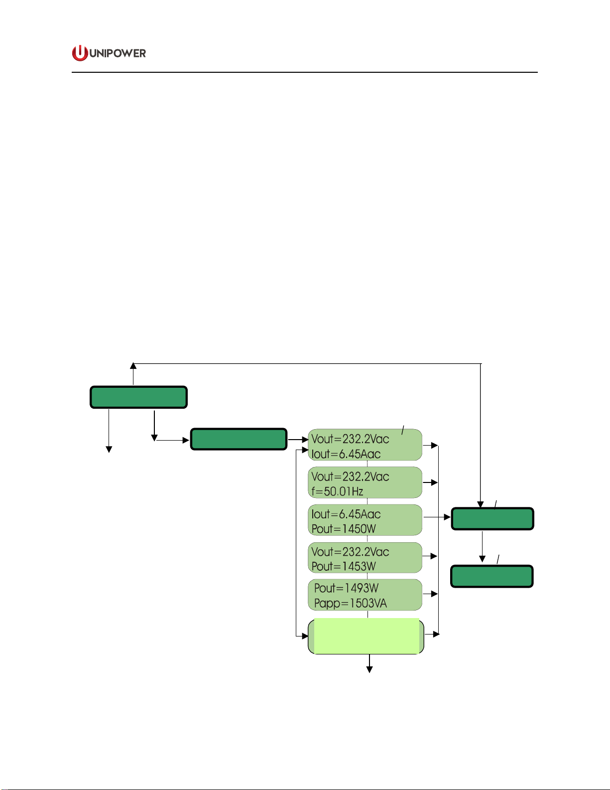
6.4 SETTINGS menu: access and submenus
You can access the SETTINGS menu starting from the STAND BY… status just by pressing the <ESC> key
or, alternatively, the <ENTER> key: see Fig.1 on page 3.
The access is protected by the 1ST level password. The default password is “0000”. To insert the "0"
character press the <ENTER> key on front panel.
With the <UP> and <DOWN> keys you can scroll all the sub-menus listed in Fig.4. Use <ENTER> to select
one of them.
The sequence of the 1ST level submenus with the setting parameters is described below (PROTECTIONS
and SERVICE submenus are addressed on the following pages).
Use <UP> and <DOWN> keys to set the "xx" parameters at the desired value. Then press <ENTER> to
confirm.
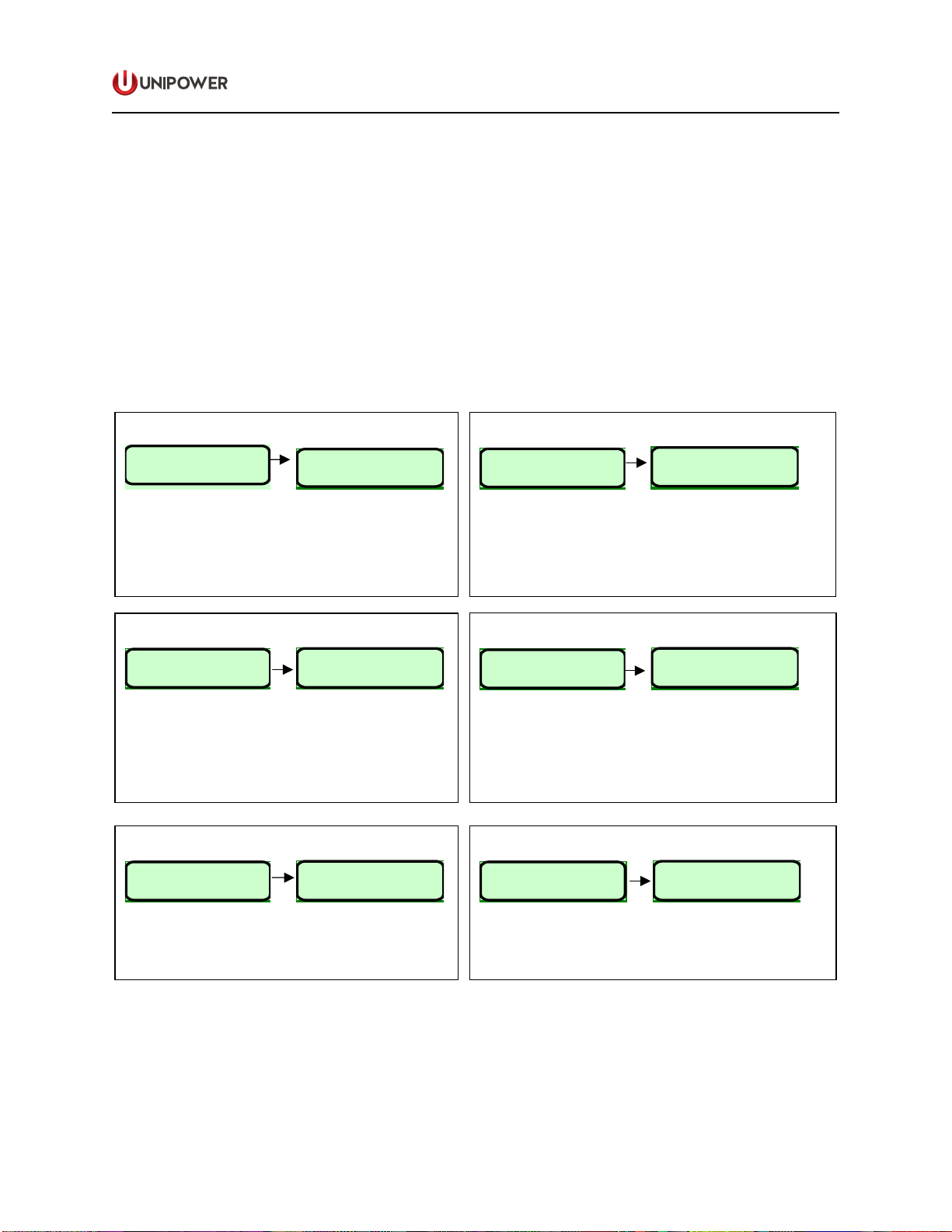
SET Vout
Set Vout - - >
1.2
Vout = xxx.x Vac - - >
1.2.1
-To set the Vout value as follows:
230Vac models: from 200Vac to 240V ac with 0.1V resolution
115Vac models: from 100Vac to 121 V ac with 0.1V resolution
- Factory setting:
230Vac models: 230Vac
115Vac models: 115Vac
SET Ilimit
Set Ilimit - - >
1.3
Ilimit = xx.x Apk
1.3.1
-To set the maximum current delivered by the unit
-Setting range:
230Vac models: 1Apk to 8Apk with 0.1A resolution
115Vac models: 0Apk to 14Apk with 0.1A resolution
-Factory setting:
230Vac models: 8 Apk
115Vac models: 14 A
k
<ENT> <ENT>
<ENT>
<ENT>
<ENT>
<ENT>
Set Address - - >
1.1 Address= xx - - >
1.1.1
SET Address
-To set the serial port address (Address = "xx").
-The address must be set only when the serial
communication in parallel configuration is used. Otherwise
you can leave the default value.
-Available address range: from 1 to 32
-Default address: 1
Set Backlight Time lenght
Light X
1.6.1
-The back light time lenght can be set from 2 to 60 sec.
- Factory setting: 20sec.
Display Light - - >
1.6
Set Key Click ON/OFF
Key click - - >
1.7
Key Click ON/OFF
1.7.1
-To enable the audible "click" when a key is pressed
-Factory setting: "Click ON"
SET Frequency
f = xx.xx Hz
1.4.1
-Setting range: 47Hz to 63Hz
-Factory setting:
230Vac models: 50Hz
115Vac models: 60Hz
Set frequency - - >
1.4
6.4 SETTINGS menu: access and submenus
You can access the SETTINGS menu starting from the STAND BY… status just by pressing the <ESC> key
or, alternatively, the <ENTER> key: see Fig.1 on page 3.
The access is protected by the 1ST level password. The default password is “0000”. To insert the "0"
character press the <ENTER> key on front panel.
With the <UP> and <DOWN> keys you can scroll all the sub-menus listed in Fig.4. Use <ENTER> to select
one of them.
The sequence of the 1ST level submenus with the setting parameters is described below (PROTECTIONS
and SERVICE submenus are addressed on the following pages).
Use <UP> and <DOWN> keys to set the "xx" parameters at the desired value. Then press <ENTER> to
confirm.
SET Vout
Set Vout - - >
1.2
Vout = xxx.x Vac - - >
1.2.1
-To set the Vout value as follows:
230Vac models: from 200Vac to 240V ac with 0.1V resolution
115Vac models: from 100Vac to 121 V ac with 0.1V resolution
- Factory setting:
230Vac models: 230Vac
115Vac models: 115Vac
SET Ilimit
Set Ilimit - - >
1.3
Ilimit = xx.x Apk
1.3.1
-To set the maximum current delivered by the unit
-Setting range:
230Vac models: 1Apk to 8Apk with 0.1A resolution
115Vac models: 0Apk to 14Apk with 0.1A resolution
-Factory setting:
230Vac models: 8 Apk
115Vac models: 14 A
k
<ENT> <ENT>
<ENT>
<ENT>
<ENT>
<ENT>
Set Address - - >
1.1 Address= xx - - >
1.1.1
SET Address
-To set the serial port address (Address = "xx").
-The address must be set only when the serial
communication in parallel configuration is used. Otherwise
you can leave the default value.
-Available address range: from 1 to 32
-Default address: 1
Set Backlight Time lenght
Light X
1.6.1
-The back light time lenght can be set from 2 to 60 sec.
- Factory setting: 20sec.
Display Light - - >
1.6
Set Key Click ON/OFF
Key click - - >
1.7
Key Click ON/OFF
1.7.1
-To enable the audible "click" when a key is pressed
-Factory setting: "Click ON"
SET Frequency
f = xx.xx Hz
1.4.1
-Setting range: 47Hz to 63Hz
-
Factory setting:
230Vac models: 50Hz
115Vac models: 60Hz
Set frequency - - >
1.4