manuals.online logo
Brands
  1. Home
  2. •
  3. Brands
  4. •
  5. SolaX Power
  6. •
  7. Inverter
  8. •
  9. SolaX Power A1-Hybrid-6.0-US User manual

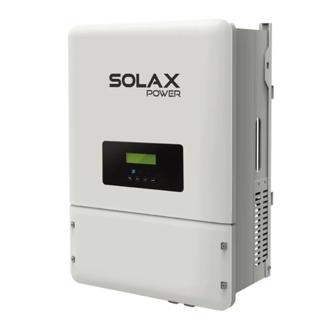
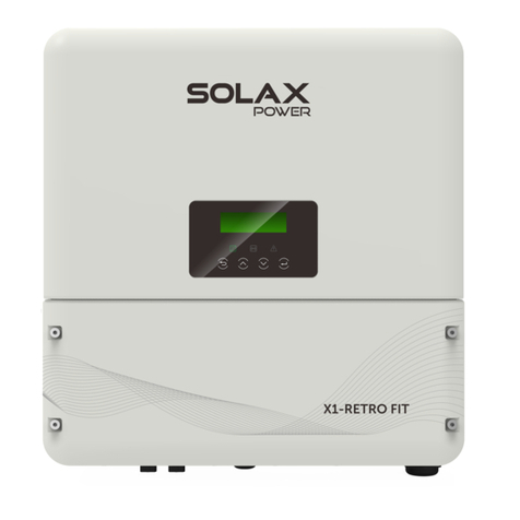
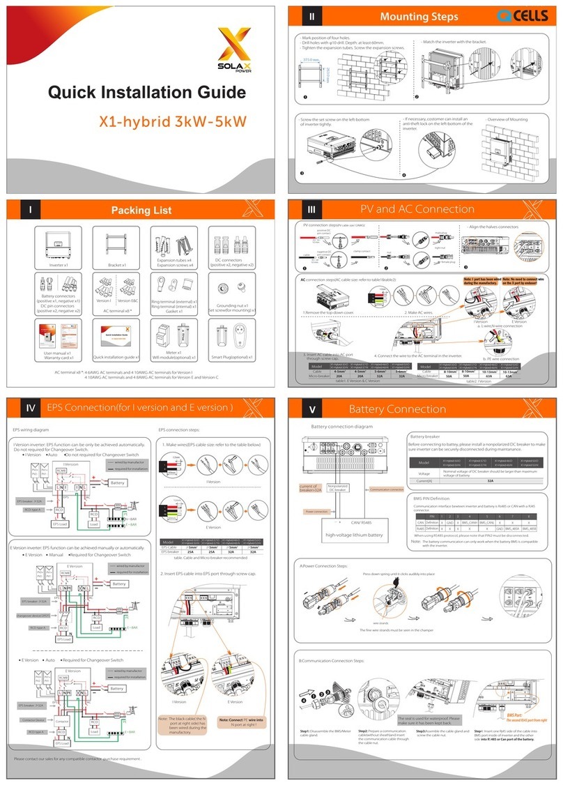
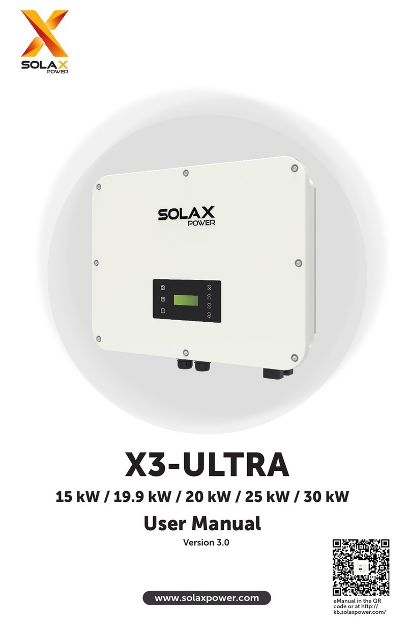
SolaX Power A1-Hybrid-6.0-US User manual

Step 3:
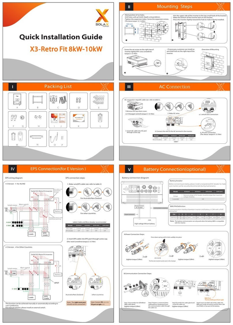
Step 1: Using the bracket as a guide, mark the positions of the twelve holes.
II
- Position the top side of the inverter on the small hook of the bracket.
- Position the bottom of the inverter to lean on the bracket.
- Press the inverter slightly towards the hole to install it rmly.
A1
User Manual x1
Warranty Card x1
A1-Hybrid 6.0KW- 8.6KW
Quick Installation Guide x1
Wi-Fi Module x1
IIII
Grounded bus-bar
IV
- The A1-Hybrid series inverter can be connected with PV modules in series with 2MPPTs for 6.0kW, 3 MPPTs for 7.0kW and 7.6kW, and 4 MPPTs for 8.6kW.
For wiring method, refer to Section III.
PV Connection
Grid Connection
For wiring method, refer to Section III.
2 L-lines and 1 N-line connect to the Grid terminal through one port.
VI
BMS Cable Connection
For wiring method, refer to Section III.
1 CAT5 network cable connects to the BMS terminal on the communication board.
Electrical Cable Connection
1 positive-line and 1 negative-line connect to BAT terminal through one port.
TRIPLE
POWER
TRIPLE
POWER
TRIPLE
POWER
+_+_+_+_+_
Grounded busbar
Battery Breaker
V
- The A1-Hybrid Series inverter can deliver output power through the load port when there is an outage.
- An autotransformer must be connected to the inverter if a user wants to use this function.
- User should select appropriate critical loads to connect to the load port. Read the user manual carefully before
selecting critical loads requirements.
2 L-lines and 1 N-line through one port;
2 L-lines and 1 N-line connect to LOAD terminal through one port.
Load Connection
2 L-lines and 1 N-line through one port;
2 L-lines and 1 N-line connect to TXS terminal through one port.
Auto-Transformer Connection
For wiring method, refer to Section III.
Load Connection
L1 N L2
LOAD
Auto-Transformer Connection
L1 N L2
TXS
Meter x1
CT x2
Inverter x1 Bracket x1
(for mounting)
Expansion Tube x12
(for mounting)
Expansion Screw x12
(for mounting) 3 PIN Terminal x1
2 PIN Terminal x1
Cord End Terminal
8.6KW x19; 7.6KW x17
7.0KW x17; 6.0KW x15
2-pole, 40A 120/240 VAC, 10kA
Grid Breaker Requirements
A1 Hybrid-6.0-US
Inverter Model Recommended AC Branch Protection
A1 Hybrid-7.0/7.6-US
2-pole, 35A 120/240 VAC, 10kA
2-pole, 45A 120/240 VAC, 10kA
A1 Hybrid-8.6-US
Required Torque
Permitted Wire Size
Plug-in
8AWG,600V,194℉/90℃ for A1 Hybrid-6.0/7.0-US
6AWG,600V,194℉/90℃ for A1 Hybrid-7.6/8.6-US
120V/240V Split-phase
L1, N, L2
Battery Breaker Requirements
Recommended DC Branch Protection
35A, 600Vdc, 35kA
Terminal: Rj45, 8-conductor
Cable: CAT5 non-crossover network cable
Cable Requirement
15.75 in/400mm
11.81 in/300mm
11.81in/300mm
11.81in/300mm
29.53 in/750mm
- Drill holes (depth of at least 2.36in/60mm) with a φ10 drill.
Step 2:
- Mount the bracket and tighten the expansion tubes. Then screw the expansion screws.
Part Required Torque
Mounting Expansion Screw (x12) 92 lbf-in
Required TorquePermitted Wire Size
Plug-in
8AWG,600V,194℉/90℃ for A1 Hybrid-6.0/7.0-US
6AWG,600V,194℉/90℃ for A1 Hybrid-7.6/8.6-US
2-pole, 40A 120/240 VAC, 10kA
Load Breaker Requirements
A1 Hybrid-6.0-US
Inverter Model Recommended AC Branch Protection
A1 Hybrid-7.0/7.6-US
2-pole, 35A 120/240VAC, 10kA
Manual Bypass Breaker Requirements (optional)
A1 Hybrid-6.0-US
Inverter Model Recommended AC Branch Protection
A1 Hybrid-7.0/7.6-US
double-pole double-throw
120/240VAC, 40A, 10kA
double-pole double-throw
120/240VAC, 35A, 10kA
2-pole, 45A 120/240 VAC, 10kA
A1 Hybrid-8.6-US
A1 Hybrid-8.6-US
double-pole double-throw
120/240VAC, 45A, 10kA
Step 1: Turn the DC switch to the “OFF” position. Remove the 8 cover screws, then remove the
cover.
Step 2: The conduit plugs (circled in blue) should be removed by the operator before
connecting the wires.
Step 3: Operator should use the standard size conduit which must fit the holes on the bottom
of the inverter. Conduit fittings must be watertight.
DC Switch
Max. 1.4 lbf- in
Max. 23 lbf- in
1G Waterproof Plugs x8
3/4G Waterproof Plugs x3
1G 3/4G
1G 1G 1G 1G
1G
3/4G 3/4G
1G
Conduit
Wirings
Conduit
0.47in/12mm
Wirings
Step 4:
4.1 Choose the appropriate wire according to the specific connection.
4.2 Remove 0.47in/12mm of the insulation from the end of the DC wire (the AC wire
shall be removed by 0.71 in/18mm).
4.3 Insert the end of wires into the Cord End Terminal, and then use the crimping
pliers to crimp the Cord End Terminal tightly (the shape will be square).
4.4 Using the slot screwdriver to compress the orange button of the terminals,
insert the stripped wires into terminal and ensure that all conductor strands are
captured in the terminal.
4.5 Loosen the slot screwdriver. Slot Screwdriver Type
SL 3
Removing Wiring Box Cover Screw Torque
Removing Conduit Plug Torque
Wiring Box of theA1-Hybrid Series Inverter
Transformer
Grounding Connection (Mandatory)
- User must earth the inverter to the home ground busbar.
- It is recommended that all devices in the system should be earthed to the home ground busbar, such as battery, loads, autotransformer, etc.
VIII
Start Inverter
Preperation for Communication Connection
Remove the Communication Board
- Remove the 2 cover screws, then remove the board.
Conduit Installation and Wiring Routing
- For this installation, refer to Section III.
- It is recommended that all communication cables should be connected
through two conduits from right hand side on the bottom of the inverter.
Communication Board Introduction
- Note in this quick installation guide, only Meter connection (Section IX), BMS connection
(Section VI) and Monitoring connection (Section XI) will be introduced in detail.
For other communication connections, refer to the Inverter User Manual.
Communication Board
Inside the Wiring Box
X
Meter Connection
- Meter connections can be divided into two parts: One is the communication connection between the meter and the inverter, and another one is the electrical cable connection between the
meter and the grid.
Communication Connection Between the Meter and the Inverter (Inverter Side)
Communication Connection Between the Meter and the Inverter (Meter Side)
- For this operation, refer to the diagram below.
Electrical Cable Connection between the Meter and the Grid
- For electrical cable installation, refer to the diagram below.
- To assist in understanding the relationship between the meter and the HYB system, a system diagram is shown below. A sub-meter is as the example show in this diagram.
For actual installation of the sub-meter, refer to specic Meter User Manual.
Characteristic Impedance: 100 to 120 ohms
Mutual capacitance: <30pF/ft (<12.5pF/ft is preferable )
Note: One shielded twisted pair, plus an additional wire for a common reference
IX
X
XIII
XII
Inverter Power On
Step 1: Turn on both the DC switch and the AC circuit breakers.
Step 2: Turn on the DC switch at the bottom of the inverter.
Step 3: Inverter will start up automatically when the PV panels generate enough power or when the battery is discharging.
LCD Display Setting
Upon rst startup, ve items need to be set in the LCD display as shown below.
0 W
>
This function allows the inverter to control energy exported to the grid.
There is a user value and a factory value. The factory value is a default which can’t be changed
by the user. The user value setting made by installer must be less than the factory value.
Step 1: Plug Pocket Wi-Fi / Pocket LAN into “Wi-Fi” port at the bottom of the inverter.
Step 2: Build the connection between the inverter and router.
Step 3: Create a user account online (Refer to the relevant User Manual for more details).
Pocket Wi-Fi / Pocket LAN / Pocket 4G Connection
The A1-Hybrid inverter can transmit inverter data to the monitoring website via an external monitoring data collector.
There are three types of monitoring data collectors, including Pocket Wi-Fi, Pocket LAN, and Pocket 4G.
XI
Max. 12 lbf-in
Required TorquePermitted Wire Size
8AWG,120V,194℉/90℃ for A1 Hybrid-6.0/7.0-US
6AWG,120V,194℉/90℃ for A1 Hybrid-7.6/8.6-US
Required Torque
Part
Max. 13.8 lbf-in
Max. 13.8 lbf-in
Removing Communication Board Cover Screw
Removing Conduit Fitting
Monitoring Installation
Cloud
Router
ØPocket LAN Connection Diagram
ØCellular Communication Module Connection Diagram
Cloud
Router
Cloud
WiFi Plus Connection Diagram
Ø
5. Check that the battery is connected.
4. Check that the meter is connected.
3. Check that all DC wirings and AC wirings are completed.
2. Check that the inverter is fixed safely on the wall.
1. Check that the main switch is in the “OFF” position. 8. Check that the PV arrays are connected.
10. Check that the loads and critical loads are connected, and that the critical loads rating is within the required rating range.
6. Check that all grounded busbars are connected.
11. Check that the generator is connected (if needed).
12. Check that the manual bypass breaker (mechanical interlock) is connected and the original state should be connected
with inverter side (if needed).
9. Check that the autotransformer is connected.
7. Check that the RSD controller is connected.
+ _+_+_+_+_
PV 1
PV 2
PV 3
PV 4
BAT
LOAD
RESERVE
L1 N L2 L1 N L2
GRID
L1 N L2
L1 N L2
Transformer
Meter Port
EPO Port
BMS
Por t
LAN
Por t
Wi-Fi/
4G Port
RPSD Port
Wi-FiInternetRouter
Wi-Fi
Gateway Cloud
WAN
Ground Busbar
PV Ar ray #1
PV Ar ray #2
PV Ar ray #3
PV Ar ray #4
RSD Mo dules
RSD Mo dules
RSD Mo dules
RSD Mo dules
PV 1+
PV 1 -
PV 2+
PV 2 -
PV 3+
PV 3 -
PV 4+
PV 4 -
RPS D CT
GROUND Busbar
Ground
Electrode
Conductor
(Ground Rod)
Battery
+
-
RPS D
Con tro lle r
N.C. N.O.
GROUND Busbar
Ground
Electrode
Conductor
(Ground Rod)
Loads
L2
CT 1
N
L1
CT 2
Neutral-Ground Bond
N L1 L2 NL1 L2
AC Backup-to
Critical Loads
NL1 L2
Auto
transformer
+
-
+
-
+
-
+
-
Wi-Fi Module or
4G Module
Emergency Stop
Switch
Signal
LEGEND
EPO Cable
LAN Cable
BMS Cable
Meter Cable
CT Cable
AC
LEGEND
HOT L1
HOT L2
Neutral
Ground
BATTERY
LEGEND
PV
LEGEND
Positive
Negative
Ground
Positive
Negative
Ground
+
-
+
-
RPSD Cable
Step 1 : Find the 3-pin female terminal block in the accessories package.
Step 2 : Choose the wires (22-24AWG), and remove 0.2in/5mm of the insulation from the end of the wire.
Step 3 : Insert the stripped wires into the female terminal block and ensure that all conductor strands are captured in the terminal.
Step 4 : Compress the female terminal head by using a slot screwdriver.
Step 5 : Plug the female terminal block into the corresponding male terminal block on the communication board tightly.
Step 3
Step 4
Conduit
0.2in/5mm
Wirings
Step 2
B-
3-pin
Step 1
A+
GND
Meter
Meter
Communication Board
Step 5 Overview
B-
A+
GND
B-
A+
G
Mode Select
> self use <
Work Mode
4. Set Work Mode
There are five Work Modes to choose from:
The battery will be charged forcibly in the setting time, allowing it to choose whether to charge from the
grid or not. The battery will stop discharging to keep higher capacity when the grid is on. Only when the
grid is down and PV energy is not sufficient will the battery start to discharge to keep the essential loads
working normally.
This work mode applies to areas that suffer from regular blackouts.
Self Use
(default)
Time of Use
Back Up Mode
The PV-generated power will first be used to supply the local loads, then to charge the battery. The
redundant power will be exported to the grid.
When there is no PV supplied, the battery will first discharge for local loads, then the grid will supply power
when the battery capacity is reached.
Charging and discharging can be set flexibly, allowing the user to select whether to charge from the grid
or not.
Parameter Comment
The priority of the inverter output power is in this order:
Feeding to the grid Supplying the load Charging the battery.
This work mode applies to areas with high feed-in tariffs.
Feed in Priority
> Mute
No
EPS system
5. Set EPS System
Inverter can work in EPS mode.
EPS System parameters can be set as below.
You can choose to mute the warning of a system that has entered into EPS mode.
“No” - there will be a buzzing sound (this is the default value). if the buzzing sound is loud, it
means that the EPS System output is overloaded.
“Yes” - shut down the warning function.
“Frequency” - can only be set to 60Hz.
> Mute
No
EPS system
6. Set Function Type
IUsers can set the type of inverter, Hybrid or AC Coupled. This option can only be set if the
inverter is . A1 Hybrid
If choose the AC Coupled, then have to restart the inverter, this function will take effect. And if you
re-select the Hybrid, you will also have to restart the inverter.
In this mode, battery discharges during two discharge window to limit demand charge (if enabled)
(Similar to Time of Use mode but on Demand Mode the system will allow grid consumption up to a
threshold limit defined by the user (default 2kW).)
Demand Mode
614.00401.03
Terminal Required TorquePermitted Wire Size
Meter
Type
3-pin Terminal Block
2.3 Ibf-in
22-24AWG
2.Set the safety standard
1.Set date time
3.Set export control

This manual suits for next models
3

Other SolaX Power Inverter manuals

SolaX Power Solax Box 3.0 User manual

SolaX Power

SolaX Power Solax Box 3.0 User manual

SolaX Power X1-Hybrid-LV User manual

SolaX Power

SolaX Power X1-Hybrid-LV User manual

SolaX Power X3-Hybrid Series User manual

SolaX Power

SolaX Power X3-Hybrid Series User manual

SolaX Power X3-Matebox advanced User manual

SolaX Power

SolaX Power X3-Matebox advanced User manual

SolaX Power X1-0.6-S User manual

SolaX Power

SolaX Power X1-0.6-S User manual

SolaX Power ZDNY-TL Series User manual

SolaX Power

SolaX Power ZDNY-TL Series User manual

SolaX Power SK-TL3000 User manual

SolaX Power

SolaX Power SK-TL3000 User manual

SolaX Power X3-Retro Fit Series User manual

SolaX Power

SolaX Power X3-Retro Fit Series User manual

SolaX Power X3-ULTRA User manual

SolaX Power

SolaX Power X3-ULTRA User manual

SolaX Power X3-Hybrid Series User manual

SolaX Power

SolaX Power X3-Hybrid Series User manual

SolaX Power BMS-PARALLEL BOX-II User manual

SolaX Power

SolaX Power BMS-PARALLEL BOX-II User manual

SolaX Power X3-Series User manual

SolaX Power

SolaX Power X3-Series User manual

SolaX Power X3-ULTRA User manual

SolaX Power

SolaX Power X3-ULTRA User manual

SolaX Power X1-2.5-S-D User manual

SolaX Power

SolaX Power X1-2.5-S-D User manual

SolaX Power X3-Retro Fit Series User manual

SolaX Power

SolaX Power X3-Retro Fit Series User manual

SolaX Power X3-Hybrid Series User manual

SolaX Power

SolaX Power X3-Hybrid Series User manual

SolaX Power X3-MEGA G2 Series User manual

SolaX Power

SolaX Power X3-MEGA G2 Series User manual

SolaX Power X3-PRO-10KW-G2 User manual

SolaX Power

SolaX Power X3-PRO-10KW-G2 User manual

SolaX Power X1 Series User manual

SolaX Power

SolaX Power X1 Series User manual

SolaX Power X1-Fit-3.7-W User manual

SolaX Power

SolaX Power X1-Fit-3.7-W User manual

SolaX Power X3-Retro Fit Series User manual

SolaX Power

SolaX Power X3-Retro Fit Series User manual

SolaX Power X3 Hybrid Series User manual

SolaX Power

SolaX Power X3 Hybrid Series User manual

SolaX Power X3-MEGA G2 Series User manual

SolaX Power

SolaX Power X3-MEGA G2 Series User manual

SolaX Power X1-0.6 User manual

SolaX Power

SolaX Power X1-0.6 User manual

Popular Inverter manuals by other brands

Omega BSG 3500R user guide

Omega

Omega BSG 3500R user guide

SEW-Eurodrive Movidrive MDX61B manual

SEW-Eurodrive

SEW-Eurodrive Movidrive MDX61B manual

Mitsubishi FR-A500 Series instruction manual

Mitsubishi

Mitsubishi FR-A500 Series instruction manual

Huawei SUN2000-33KTL-US user manual

Huawei

Huawei SUN2000-33KTL-US user manual

Connectland G-180AF user guide

Connectland

Connectland G-180AF user guide

Samlexpower PST-100S-12A owner's manual

Samlexpower

Samlexpower PST-100S-12A owner's manual

Fusion 25512 Use and care guide

Fusion

Fusion 25512 Use and care guide

SAJ C6 Series user manual

SAJ

SAJ C6 Series user manual

GE HOME NERATOR SYSTEM 27000-30000 WATT - Installation and start-up manual

GE

GE HOME NERATOR SYSTEM 27000-30000 WATT - Installation and start-up manual

Growatt MIN 2500 TL-XE quick guide

Growatt

Growatt MIN 2500 TL-XE quick guide

Envertech EVT300 Quick installation guide

Envertech

Envertech EVT300 Quick installation guide

WFCO WF-5118 Operator's manual

WFCO

WFCO WF-5118 Operator's manual

Epever LD150S-N1 user manual

Epever

Epever LD150S-N1 user manual

ICT Sine Wave ICT1500-12W instruction manual

ICT

ICT Sine Wave ICT1500-12W instruction manual

Hoymiles HMT-2250/1800-6T Quick installation guide

Hoymiles

Hoymiles HMT-2250/1800-6T Quick installation guide

SMA SUNNY HIGHPOWER PEAK3 SHP 100-20 operating manual

SMA

SMA SUNNY HIGHPOWER PEAK3 SHP 100-20 operating manual

Deye SUN-40K-G-LV user manual

Deye

Deye SUN-40K-G-LV user manual

m-Dimension ADI-12W6 owner's manual

m-Dimension

m-Dimension ADI-12W6 owner's manual

manuals.online logo
manuals.online logoBrands
  • About & Mission
  • Contact us
  • Privacy Policy
  • Terms and Conditions

Copyright 2025 Manuals.Online. All Rights Reserved.