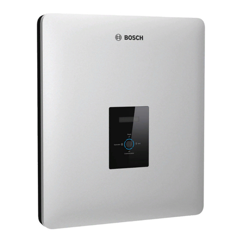
Bosch Rexroth IndraDrive ML Series Technical manual

Rexroth IndraDrive ML
Drive Systems with HMU05
Project Planning Manual
R911344279
Edition 02

Rexroth IndraDrive ML
Drive Systems with HMU05
Project Planning Manual
DOK-INDRV*-HXX05******-PR02-EN-P
RS-bdff4382be37d8ef0a6846a5002ff107-2-en-US-3
● Overview of the Rexroth IndraDrive Hxx05 system
● Description of the allowed system component combinations
● Selection of the drive system components
● Specification applying to all components (ambient and operating condi‐
tions)
● Application description of system characteristics
Edition Release Date Notes
02 2016-09 Revised edition
01 2014-10 First edition
Copyright © Bosch Rexroth AG 2016
This document, as well as the data, specifications and other information set
forth in it, are the exclusive property of Bosch Rexroth AG. It may not be re‐
produced or given to third parties without its consent.
Liability The specified data is intended for product description purposes only and shall
not be deemed to be a guaranteed characteristic unless expressly stipulated
in the contract. All rights are reserved with respect to the content of this docu‐
mentation and the availability of the product.
Title
Type of Documentation
Document Typecode
Internal File Reference
Purpose of Documentation
Record of Revision
Bosch Rexroth AG DOK-INDRV*-HXX05******-PR02-EN-P
Rexroth IndraDrive ML Drive Systems with HMU05

Table of Contents
Page
1 System presentation.................................................................................................... 11
1.1 Rexroth IndraDrive ML range............................................................................................................... 11
1.1.1 Overview – Rexroth IndraDrive ML.................................................................................................... 11
1.1.2 Target applications............................................................................................................................ 13
1.1.3 Features............................................................................................................................................ 14
Functional features......................................................................................................................... 14
Performance features..................................................................................................................... 15
Interfaces........................................................................................................................................ 15
Supported encoder systems........................................................................................................... 16
1.2 System configuration............................................................................................................................ 17
1.2.1 System structure................................................................................................................................ 17
1.2.2 System components.......................................................................................................................... 18
HMU05 universal inverter............................................................................................................... 18
HMU05 type code........................................................................................................................ 18
Control sections.............................................................................................................................. 20
Optional cards................................................................................................................................ 24
Installing and removing control sections and optional cards.......................................................... 25
Training........................................................................................................................................ 25
ESD protection............................................................................................................................ 25
Limited number of insertions and removals................................................................................. 25
Instructions.................................................................................................................................. 26
Firmware......................................................................................................................................... 27
1.2.3 About this documentation.................................................................................................................. 28
Purpose.......................................................................................................................................... 28
Documentations.............................................................................................................................. 28
Drive systems, system components............................................................................................ 28
Firmware...................................................................................................................................... 28
Your feedback................................................................................................................................ 29
2 Important directions for use ........................................................................................ 31
2.1 Appropriate use ................................................................................................................................... 31
2.1.1 Introduction........................................................................................................................................ 31
2.1.2 Areas of use and application............................................................................................................. 31
2.2 Inappropriate use.................................................................................................................................. 32
3 Safety instructions for electric drives and controls....................................................... 33
3.1 Definitions of terms............................................................................................................................... 33
3.2 General information.............................................................................................................................. 34
3.2.1 Using the Safety instructions and passing them on to others............................................................ 34
3.2.2 Requirements for safe use................................................................................................................ 34
3.2.3 Hazards by improper use.................................................................................................................. 35
3.3 Instructions with regard to specific dangers.......................................................................................... 37
3.3.1 Protection against contact with electrical parts and housings........................................................... 37
DOK-INDRV*-HXX05******-PR02-EN-P Bosch Rexroth AG I/407
Rexroth IndraDrive ML Drive Systems with HMU05
Table of Contents

Page
3.3.2 Protective extra-low voltage as protection against electric shock .................................................... 38
3.3.3 Protection against dangerous movements........................................................................................ 39
3.3.4 Protection against electromagnetic and magnetic fields during operation and mounting.................. 40
3.3.5 Protection against contact with hot parts........................................................................................... 40
3.3.6 Protection during handling and mounting.......................................................................................... 41
3.3.7 Battery safety..................................................................................................................................... 41
3.3.8 Protection against pressurized systems............................................................................................ 42
3.4 Explanation of signal words and the Safety alert symbol..................................................................... 42
4 Combining the individual components......................................................................... 45
4.1 Documentations.................................................................................................................................... 45
4.2 Brief description of individual components........................................................................................... 45
4.2.1 HMU05 - brief description and design............................................................................................... 45
4.3 Configuring the drive system................................................................................................................ 47
4.3.1 Firmware............................................................................................................................................ 47
Firmware and device types............................................................................................................. 47
4.3.2 Motors................................................................................................................................................ 47
Third-party motors.......................................................................................................................... 47
General information on third-party motors................................................................................... 47
Requirements on third-party motors............................................................................................ 48
Third-party motor encoder requirements..................................................................................... 50
Notes on selection and commissioning....................................................................................... 51
4.3.3 Cables............................................................................................................................................... 52
Motor power cable.......................................................................................................................... 52
Encoder cables............................................................................................................................... 52
4.3.4 Leakage capacitances....................................................................................................................... 53
Allowed leakage capacitances....................................................................................................... 53
HMU05 systems for medium leakage capacitances....................................................................... 53
HMU05 systems with a single supply unit................................................................................... 53
HMU05 systems with supply units connected in parallel............................................................. 53
HMU05 systems for high leakage capacitances............................................................................. 54
DC bus choke, Y capacitor pairs................................................................................................. 54
HMU05 systems with a single supply unit................................................................................... 54
HMU05 systems with supply units connected in parallel............................................................. 55
Operating HMU05 together with HMS01/HMD01........................................................................... 56
Topologies................................................................................................................................... 56
HMU05 systems without a central DC bus choke....................................................................... 57
HMU05 systems with a central DC bus choke............................................................................ 59
4.4 Installation conditions........................................................................................................................... 60
4.4.1 Ambient and operating conditions..................................................................................................... 60
4.4.2 Control cabinet.................................................................................................................................. 62
Air cooling....................................................................................................................................... 62
Control cabinet design and cooling............................................................................................. 62
Liquid cooling.................................................................................................................................. 63
General information..................................................................................................................... 63
Cooling devices........................................................................................................................... 63
Bosch Rexroth AG DOK-INDRV*-HXX05******-PR02-EN-PII/407
Rexroth IndraDrive ML Drive Systems with HMU05
Table of Contents

Page
Cooling device components........................................................................................................ 65
Cooling of the drive components................................................................................................. 73
Coolant........................................................................................................................................ 77
Sizing liquid cooling..................................................................................................................... 78
4.4.3 UL ratings.......................................................................................................................................... 79
Introduction..................................................................................................................................... 79
Inverter........................................................................................................................................... 79
Supply units.................................................................................................................................... 80
4.4.4 Compatibility with foreign matters...................................................................................................... 81
4.5 Mechanical project planning................................................................................................................. 82
4.5.1 Dimensions........................................................................................................................................ 82
HMU05.1N-F0140-0350................................................................................................................. 82
HMU05.1N-F0170-0430................................................................................................................. 83
HMU05.1N-F0220-0510................................................................................................................. 84
HMU05.1N-F0270-0660................................................................................................................. 85
HMU05.1N-F0340-0820................................................................................................................. 86
HMU05.1N-F0430-1040................................................................................................................. 87
HMU05.1N-F0540-1300................................................................................................................. 88
4.5.2 Dimensions, mass, insulation, sound pressure level ........................................................................ 89
4.5.3 Temperatures, cooling, power dissipation, distances........................................................................ 90
4.5.4 Mounting positions of components.................................................................................................... 93
4.6 Electrical project planning..................................................................................................................... 94
4.6.1 Overall connection diagram (HMU05 as drive controller).................................................................. 94
4.6.2 Overall connection diagram (HMU05 as supply unit)........................................................................ 95
Overall connection diagram with load contactor............................................................................. 95
Overall connection diagram with a controllable main switch.......................................................... 96
4.6.3 Project planning of control voltage.................................................................................................... 98
Control voltage for drive systems................................................................................................... 98
Sizing the control voltage supply.................................................................................................... 98
Determining the power requirements.......................................................................................... 98
Requirements on the 24V power supply unit............................................................................. 100
Installing the 24V supply............................................................................................................ 101
4.6.4 Mains connection............................................................................................................................. 102
Residual-current-operated circuit breakers (RCD, RCCB) as additional fusing........................... 102
General information................................................................................................................... 102
Cause of leakage currents......................................................................................................... 103
Possibilities of use..................................................................................................................... 103
Mains types.................................................................................................................................. 104
TN-S mains type........................................................................................................................ 104
TN-C mains type........................................................................................................................ 105
IT mains type............................................................................................................................. 106
TT system.................................................................................................................................. 107
Mains with grounded outer conductor (Corner-grounded delta mains)..................................... 107
Mains connection type.................................................................................................................. 108
Mains connected load and mains current .................................................................................... 110
Technical data of the components............................................................................................. 110
DOK-INDRV*-HXX05******-PR02-EN-P Bosch Rexroth AG III/407
Rexroth IndraDrive ML Drive Systems with HMU05
Table of Contents

Page
Calculating the mains-side phase current ................................................................................ 110
Dimensioning the line cross sections and fuses........................................................................... 111
Dimensioning and selecting the mains transformer...................................................................... 111
Combining mains filter, mains choke, preconnected choke and capacitance pack...................... 112
4.6.5 Running multiple HMU05s in parallel.............................................................................................. 114
4.7 Acceptance tests and approvals......................................................................................................... 117
5 Condition as supplied, identification, transport and storage...................................... 119
5.1 Condition as supplied......................................................................................................................... 119
5.1.1 Factory testing................................................................................................................................. 119
Voltage testing and insulation resistance testing.......................................................................... 119
5.1.2 Customer testing............................................................................................................................. 119
5.2 Identification........................................................................................................................................ 120
5.2.1 Type plates...................................................................................................................................... 120
Design.......................................................................................................................................... 120
5.2.2 Contents of delivery......................................................................................................................... 120
5.3 Transporting components................................................................................................................... 120
5.4 Storing components............................................................................................................................ 121
6 Mounting and installation........................................................................................... 123
6.1 Mounting HMU05 devices in control cabinet...................................................................................... 123
6.2 Electrical connection........................................................................................................................... 123
6.2.1 Overall connection diagram (HMU05 as drive controller)................................................................ 123
6.2.2 Overall connection diagram (HMU05 as supply unit)...................................................................... 123
Overall connection diagram with load contactor........................................................................... 123
Overall connection diagram with controllable main switch........................................................... 123
6.2.3 Connection points............................................................................................................................ 124
Arrangement of HMU05 connection points................................................................................... 124
Connection point of equipment grounding conductor................................................................... 125
L1, L2, L3, mains/motor connection............................................................................................. 126
Important notes.......................................................................................................................... 126
XG3, motor temperature monitoring, motor holding brake, motor fan control ............................. 127
XG32, HNA bus............................................................................................................................ 129
XG1, IndraBus.............................................................................................................................. 129
XD10, 24 V supply (control voltage)............................................................................................. 129
L+ L-, DC bus connection............................................................................................................. 130
Shield connection......................................................................................................................... 131
Ground connection....................................................................................................................... 133
6.2.4 Optional cards................................................................................................................................. 134
HPC01.1-MN0x-NN...................................................................................................................... 134
HPC01.1-P001-NN....................................................................................................................... 134
6.3 WATER IN/OUT, cooling liquid connection........................................................................................ 135
7 Technical data of the components............................................................................. 137
7.1 Ambient and operating conditions...................................................................................................... 137
Bosch Rexroth AG DOK-INDRV*-HXX05******-PR02-EN-PIV/407
Rexroth IndraDrive ML Drive Systems with HMU05
Table of Contents

Page
7.2 Power section..................................................................................................................................... 137
7.2.1 Control voltage................................................................................................................................ 137
7.2.2 Mains voltage.................................................................................................................................. 139
7.2.3 DC bus............................................................................................................................................. 141
7.2.4 Inverter............................................................................................................................................ 143
8 Cables, accessories, additional components............................................................. 147
8.1 Overview............................................................................................................................................. 147
8.1.1 Cables............................................................................................................................................. 147
8.1.2 Accessories..................................................................................................................................... 147
8.1.3 Additional components.................................................................................................................... 147
8.2 Accessories........................................................................................................................................ 148
8.2.1 Mounting and connection accessories (HAS03).............................................................................. 148
8.2.2 Cabinet installation kit (HAS08.1-008)............................................................................................. 149
Type code..................................................................................................................................... 149
Parts............................................................................................................................................. 150
Mounting....................................................................................................................................... 151
On top of control cabinet........................................................................................................... 151
In front of control cabinet........................................................................................................... 152
Mounting the device.................................................................................................................. 154
Dismounting the device............................................................................................................. 156
8.2.3 Blank covers, motor monitor grounding, mounting plates (HAS10)................................................. 157
HAS10 type code.......................................................................................................................... 157
Blank covers (HAS10.1-002-003)................................................................................................. 157
Motor monitor grounding (HAS10.1-002-004).............................................................................. 160
Mounting plate for device width 200 mm (HAS10.1-002-005)...................................................... 162
Mounting plate for device width 220 mm (HAS10.1-002-006)...................................................... 164
8.3 Additional components....................................................................................................................... 166
8.3.1 HNA05 mains connection module................................................................................................... 166
HNA05 type code......................................................................................................................... 166
Dimensions................................................................................................................................... 167
Data.............................................................................................................................................. 169
Connection points......................................................................................................................... 171
Overview.................................................................................................................................... 171
Equipment grounding conductor connection point.................................................................... 172
XD1, mains voltage, equipment grounding conductor............................................................... 173
XD2, DC bus.............................................................................................................................. 174
XD10, 24 V supply (control voltage).......................................................................................... 175
XG1, IndraBus........................................................................................................................... 176
XG31, messages....................................................................................................................... 177
XG32, HNA bus......................................................................................................................... 179
XG33, on, off, ZKS (DC bus short circuit) status....................................................................... 180
XG34, mains contactor (contact)............................................................................................... 182
XG40, mains contactor (acknowledgment messages).............................................................. 183
Display elements.......................................................................................................................... 184
8.3.2 HNC05 mains capacitor................................................................................................................... 185
DOK-INDRV*-HXX05******-PR02-EN-P Bosch Rexroth AG V/407
Rexroth IndraDrive ML Drive Systems with HMU05
Table of Contents
Page
HNC05 type code......................................................................................................................... 185
Dimensions................................................................................................................................... 186
HNC05.1N-0050........................................................................................................................ 186
HNC05.1N-0075........................................................................................................................ 187
HNC05.1N-0100........................................................................................................................ 188
Data.............................................................................................................................................. 189
Assignment to HMU05.................................................................................................................. 189
8.3.3 HNF05 mains filter........................................................................................................................... 190
HNF05 type code.......................................................................................................................... 190
Dimensions................................................................................................................................... 192
HNF05.1A-500N-R0250............................................................................................................ 192
HNF05.1A-500N-R0320, -R0400.............................................................................................. 193
HNF05.1A-500N-R0600............................................................................................................ 194
HNF05.1A-500N-R1000............................................................................................................ 195
HNF05.1A-500N-R1600............................................................................................................ 196
Mounting....................................................................................................................................... 196
Data.............................................................................................................................................. 197
Assignment to HMU05.................................................................................................................. 197
8.3.4 HNL05 mains choke........................................................................................................................ 198
HNL05 type code.......................................................................................................................... 198
Type plate..................................................................................................................................... 202
Dimensions................................................................................................................................... 203
HNL05.1R-0219-N0218............................................................................................................. 203
HNL05.1R-0182-N0262............................................................................................................. 204
HNL05.1R-0045-N0327............................................................................................................. 205
HNL05.1R-0135-N0327............................................................................................................. 206
HNL05.1R-0054-N0409............................................................................................................. 207
HNL05.1R-0117-N0409............................................................................................................. 208
HNL05.1R-0043-N0514............................................................................................................. 209
HNL05.1R-0130-N0514............................................................................................................. 210
HNL05.1R-0050-N0652............................................................................................................. 211
HNL05.1R-0113-N0652............................................................................................................. 212
HNL05.1R-0040-N0811............................................................................................................. 213
HNL05.1R-0100-N0811............................................................................................................. 214
HNL05.1R-0040-N1019............................................................................................................. 215
HNL05.1R-0094-N1019............................................................................................................. 216
Data.............................................................................................................................................. 217
Water cooling................................................................................................................................ 218
Connection................................................................................................................................... 218
Assignment to HMU05.................................................................................................................. 218
8.3.5 HML05 motor choke/balancing choke............................................................................................. 219
HML05 type code......................................................................................................................... 219
HML05 to HMU05 assignment..................................................................................................... 220
Dimensions................................................................................................................................... 221
Data.............................................................................................................................................. 229
8.3.6 HLL05 DC bus choke...................................................................................................................... 231
Bosch Rexroth AG DOK-INDRV*-HXX05******-PR02-EN-PVI/407
Rexroth IndraDrive ML Drive Systems with HMU05
Table of Contents
Page
HLL05 type code.......................................................................................................................... 231
Sizing............................................................................................................................................ 232
Dimensions................................................................................................................................... 233
HLL05.1W-04M0-S0202............................................................................................................ 233
HLL05.1F-04M0-S0202............................................................................................................. 234
HLL05.1F-04M0-S0243............................................................................................................. 235
HLL05.1W-04M0-S0303............................................................................................................ 236
HLL05.1F-04M0-S0303............................................................................................................. 237
HLL05.1F-04M0-S0380............................................................................................................. 238
HLL05.1F-04M0-S0475............................................................................................................. 239
HLL05.1F-04M0-S0603............................................................................................................. 240
HLL05.1F-04M0-S0720............................................................................................................. 241
HLL05.1F-04M0-S0942............................................................................................................. 242
Data.............................................................................................................................................. 243
Water cooling................................................................................................................................ 244
Assignment................................................................................................................................... 245
Circuit diagram............................................................................................................................. 246
Connection................................................................................................................................... 246
8.3.7 Y capacitor pair (HAS04.1-003)....................................................................................................... 247
Type code..................................................................................................................................... 247
Data.............................................................................................................................................. 247
8.3.8 HLR05 external braking resistor...................................................................................................... 249
HLR05 type code.......................................................................................................................... 249
Dimensions................................................................................................................................... 250
HLR05.1W-54K0-N05R4, …-70K0-N04R0............................................................................... 250
Data.............................................................................................................................................. 251
Installation.................................................................................................................................... 252
8.3.9 HLT05 braking unit.......................................................................................................................... 255
HLT05 type code.......................................................................................................................... 255
Dimensions................................................................................................................................... 256
Data.............................................................................................................................................. 259
Connection diagram..................................................................................................................... 260
Connection points......................................................................................................................... 263
Overview.................................................................................................................................... 263
XE01, equipment grounding conductor connection point.......................................................... 265
XD02, DC bus............................................................................................................................ 267
XD4, braking resistor................................................................................................................. 271
XD10, 24 V supply (control voltage).......................................................................................... 272
XG1, IndraBus........................................................................................................................... 273
XG3, braking resistor overtemperature signal contact.............................................................. 274
XG31, signal contact (Bb, warning) and reset input.................................................................. 275
XG33, DC bus short-circuit (ZKS)............................................................................................. 277
SF1 switch.................................................................................................................................... 278
Display elements.......................................................................................................................... 279
8.3.10 24V power supply unit..................................................................................................................... 280
Features....................................................................................................................................... 280
DOK-INDRV*-HXX05******-PR02-EN-P Bosch Rexroth AG VII/407
Rexroth IndraDrive ML Drive Systems with HMU05
Table of Contents
Page
Data.............................................................................................................................................. 281
24V/20A connection diagram....................................................................................................... 282
24V/40A connection diagram....................................................................................................... 283
8.3.11 Heat Exchanger HAH01.................................................................................................................. 284
Type Code HAH01....................................................................................................................... 284
General Information...................................................................................................................... 285
Manufacturer’s details and machine identification details......................................................... 285
Declaration of conformity........................................................................................................... 286
Disclaimer notice....................................................................................................................... 287
Safety Information........................................................................................................................ 288
General safety warnings............................................................................................................ 288
Liquid-Liquid Heat Exchanger...................................................................................................... 289
Technical Information................................................................................................................ 289
Information concerning handling and installation...................................................................... 301
Information for Use.................................................................................................................... 307
Maintenance Information........................................................................................................... 315
Breakdown Information.............................................................................................................. 317
Information Concerning Replacements..................................................................................... 318
Hydraulic diagrams.................................................................................................................... 322
Air-Liquid Heat Exchanger............................................................................................................ 326
Technical Information................................................................................................................ 326
Information Concerning Handling and Installation..................................................................... 339
Information for Use.................................................................................................................... 346
Maintenance Information........................................................................................................... 353
Breakdown Information.............................................................................................................. 355
Information Concerning Replacements..................................................................................... 356
Hydraulic diagrams.................................................................................................................... 362
9 Environmental protection and disposal ..................................................................... 365
9.1 Environmental protection.................................................................................................................... 365
9.2 Disposal.............................................................................................................................................. 365
10 Service and support................................................................................................... 367
11 Appendix.................................................................................................................... 369
11.1 Switching supply units on and off....................................................................................................... 369
11.1.1 Switching on.................................................................................................................................... 369
11.1.2 Switching off.................................................................................................................................... 370
11.2 Dimensioning the line cross sections and fuses ................................................................................ 371
11.3 DC bus fuses...................................................................................................................................... 380
11.4 Aluminum contact points and cupal disks........................................................................................... 381
11.4.1 Introduction...................................................................................................................................... 381
11.4.2 Preparation...................................................................................................................................... 381
11.4.3 Cupal disk........................................................................................................................................ 381
11.5 Determining the leakage capacitance................................................................................................. 383
Bosch Rexroth AG DOK-INDRV*-HXX05******-PR02-EN-PVIII/407
Rexroth IndraDrive ML Drive Systems with HMU05
Table of Contents
Page
11.6 Leakage capacitances........................................................................................................................ 384
11.6.1 Leakage capacitance of power cables ........................................................................................... 384
11.7 Total Harmonic Distortion (THD)........................................................................................................ 385
11.8 Liquid cooling...................................................................................................................................... 387
11.8.1 Sizing liquid cooling......................................................................................................................... 387
Calculation criteria........................................................................................................................ 387
Physical data............................................................................................................................. 387
Flow rate.................................................................................................................................... 387
Pressure decrease.................................................................................................................... 388
Sizing aids.................................................................................................................................... 389
11.8.2 Sizing example................................................................................................................................ 394
Index.......................................................................................................................... 399
DOK-INDRV*-HXX05******-PR02-EN-P Bosch Rexroth AG IX/407
Rexroth IndraDrive ML Drive Systems with HMU05
Table of Contents
Bosch Rexroth AG DOK-INDRV*-HXX05******-PR02-EN-PX/407
Rexroth IndraDrive ML Drive Systems with HMU05

1 System presentation
1.1 Rexroth IndraDrive ML range
1.1.1 Overview – Rexroth IndraDrive ML
Rexroth IndraDrive ML
HMU05
Tab. 1-1: HMU05 universal inverter of the Rexroth IndraDrive ML product
range
DOK-INDRV*-HXX05******-PR02-EN-P Bosch Rexroth AG 11/407
Rexroth IndraDrive ML Drive Systems with HMU05
System presentation

Supply unit Drive controller
*Only relevant to high-performance HMU05
HNA05 Mains connection module
HMU05 Universal inverter
CSB02.5 Control section with firmware for supply units
(FWA‑INDRV*‑PSB‑…)
HPC01 Motor/mains module
HNC05 Mains capacitor
HNL05 Choke
HNF05 Mains filter
Fig. 1-1: Supply unit components
HMU05 Universal inverter
CSx02.5 Control section with firmware for drive con‐
trollers (FWA‑INDRV*‑MPx‑…)
HPC01 Motor/mains module
HML05 Motor choke (optional)
HMF05 Motor filter (optional)
Fig. 1-2: Drive controller components
Tab. 1-2: Supply unit, drive controller
HMV05 HMV05 is the designation for a supply unit consisting of an HNA05 mains
connecting module, HMU05 universal inverter and CSB02.5 control section
with firmware for supply units (FWA-INDRV*-PSB-...).
HMV05 is not an official product designation and is used solely for documen‐
tation purposes.
HMS05 HMS05 is the designation for a drive controller consisting of an HMU05
universal inverter and CSx02.5 control section with firmware for drive control‐
lers (FWA-INDRV*-MPx-...).
HMS05 is not an official product designation and is used solely for documen‐
tation purposes.
Bosch Rexroth AG DOK-INDRV*-HXX05******-PR02-EN-P12/407
Rexroth IndraDrive ML Drive Systems with HMU05
System presentation

1.1.2 Target applications
Metal forming
● Servo press main drive
● Winders
● Straightener drives
● Profiler drives
Plastics
● Extruders
● Kneaders
● Pumps
● Injector and profiling axis drives
Marine/offshore technology
● Fishing winches
● Anchor handling winches
● Nautical winches
● Shiplifts
Metallurgy
● Roller conveyors
● Transfer lifters
Others
● Paper manufacturing (pumps, rollers)
● Printing machines (winding computation, cross cutters, rollers)
● General automation (pumps, cranes, testing stations)
Tab. 1-3: Target applications
DOK-INDRV*-HXX05******-PR02-EN-P Bosch Rexroth AG 13/407
Rexroth IndraDrive ML Drive Systems with HMU05
System presentation

1.1.3 Features
Functional features
● Universal power sections for inverters and regenerative supply units
● Power sections with the same output can be connected in parallel
● Compact type of construction
● Degree of protection of device: IP20; degree of protection of connec‐
tions: IP00
● CSx02.5 control section
● Control panel with programming module function
● Scalable signal processing and firmware
● Multi-encoder interface for all standard encoders
● DC bus connection
● Analog input (14 bit, ±10 V)
● Cooling type: Liquid cooling
Bosch Rexroth AG DOK-INDRV*-HXX05******-PR02-EN-P14/407
Rexroth IndraDrive ML Drive Systems with HMU05
System presentation

Performance features
Inverter
HMU05.1N-… → 0140-0350 0170-0430 0220-0510 0270-0660 0340-0820 0430-1040 0540-1300 0680-1690
Continuous cur‐
rent
A 254 306 392 490 616 771 1002 1185
Maximum current A 357 427 515 660 825 1037 1297 1686
Typical motor
power 1)
kW 132 | 110 160 | 132 200 | 160 250 | 200 315 | 250 400 | 315 500 | 400 630 | 500
1) x | y; x = basic load for 540 s, 10% overload for 60 s; y = basic
load for 540 s, 50% overload for 60 s
Tab. 1-4: HMU05.1N, inverter performance features
Supply unit
HMU05.1N-… → 0140-0350 0170-0430 0220-0510 0270-0660 0340-0820 0430-1040 0540-1300 0680-1690
Mains connection
voltage
ULN
V 3 AC 380 … 500; -15%, +10%
Mains input cur‐
rent (basic pow‐
er) 1)
A 216 | 180 260 | 216 324 | 260 405 | 324 509 | 405 645 | 509 803 | 645 1009 | 803
Basic DC bus
power 1)
kW 144 | 120 173 | 144 216 | 173 270 | 216 339 | 270 430 | 339 535 | 430 672 | 535
DC bus overload
capacity 1)
PDC_max
kW 158 | 180 190 | 216 238 | 260 297 | 324 373 | 405 473 | 509 589 | 645 739 | 803
Continuous DC
bus power
PDC_cont
kW 145 174 219 273 342 435 540 679
1) x | y; x = basic load for 540 s, 10% overload for 60 s; y = basic
load for 540 s, 50% overload for 60 s
Tab. 1-5: HMU05.1N, supply unit performance features
Interfaces
Overview ● Compatible with IndraDrive platform
● Ethernet-based communication with the following supported protocols:
– sercos III
– PROFINET IO
– EtherNet/IP
– EtherNet POWERLINK
– EtherCAT
● Alternative communication:
– PROFIBUS
– CANopen
DOK-INDRV*-HXX05******-PR02-EN-P Bosch Rexroth AG 15/407
Rexroth IndraDrive ML Drive Systems with HMU05
System presentation

● Optional safety technology
● Optional multi-encoder interface
● Optional encoder emulation
● Analog input
● Freely configurable digital inputs/outputs
● Optional I/O extension digital/analog
Supported encoder systems
Supported encoder systems Encoder systems with a supply voltage of 5 and 12 V:
● IndraDyn encoder
● 1Vpp sin-cos encoder; HIPERFACE®
● 1Vpp sin-cos encoder; EnDat 2.1; EnDat 2.2
● 1Vpp sin-cos encoder; with reference track
● 5V TTL square-wave encoder; with reference track
● SSI
● Combined encoder for SSI (combination of SSI and 1Vpp sin-cos encod‐
er)
● Resolver
Bosch Rexroth AG DOK-INDRV*-HXX05******-PR02-EN-P16/407
Rexroth IndraDrive ML Drive Systems with HMU05
System presentation

1.2 System configuration
1.2.1 System structure
*Optional
** Only relevant to high-performance HMU05
24V 24V power supply unit (AC/DC power supply unit; optional
DC/DC power supply unit for redundancy in the case of mains
failure)
HLL DC bus choke
HLR Braking resistor
HLT Braking unit
HMF Motor filter
HML Motor choke
HMU Universal inverter
HNA Mains connection module
HNC Mains capacitor
HNF Mains filter
HNL Choke
MMotor
Fig. 1-3: Rexroth IndraDrive ML drive system
DOK-INDRV*-HXX05******-PR02-EN-P Bosch Rexroth AG 17/407
Rexroth IndraDrive ML Drive Systems with HMU05
System presentation

1.2.2 System components
HMU05 universal inverter
HMU05 type code
Short type designation 1 2 3 4 5 6 7 8 9
1
0123456789
2
0123456789
3
0123456789
4
0
Example: H M U 0 5 . 1 N - F 0 2 7 0 - 0 6 6 0 - N - A 4 - D 7 - N 1 N - N N N N
① ② ③④ ⑤ ⑥ ⑦ ⑧ ⑨⑩⑪ ⑫
①Product:
HMU = Universal inverter
②Series:
05 = 05
③Design:
1 = 1
④Application:
N = Standard
⑤Cooling type:
F = Liquid cooling
W = Air, internal
⑥DC bus continuous power / maximum current 4):
0140-0210 = 140 kW / 210 A
0140-0350 = 140 kW / 350 A
0170-0250 = 170 kW / 250 A
0170-0430 = 170 kW / 430 A
0220-0300 = 220 kW / 300 A
0220-0510 = 220 kW / 510 A
0270-0370 = 270 kW / 370 A
0270-0660 = 270 kW / 660 A
0340-0820 = 340 kW / 820 A
0400-0600 = 400 kW / 600 A
0430-1040 = 430 kW / 1040 A
0540-0750 = 540 kW / 750 A
0540-1300 = 540 kW / 1300 A
0680-0980 = 680 kW / 980 A
0680-1690 = 680 kW / 1690 A
⑦Degree of protection:
N = IP00
⑧Mains connection voltage / Nominal DC bus voltage:
A4-D7 = supply unit: 3 x AC 380 V -15% ... 500V +10%; inverter: DC 750 V
A5-11 = supply unit: 3 x AC 525 V -15% ... 690V +10%; inverter: DC 1100 V
Bosch Rexroth AG DOK-INDRV*-HXX05******-PR02-EN-P18/407
Rexroth IndraDrive ML Drive Systems with HMU05
System presentation
This manual suits for next models
9
Table of contents
Other Bosch Inverter manuals

Bosch
Bosch SE3000 Series Assembly instructions

Bosch
Bosch c-Si M 48 EU Operating instructions

Bosch
Bosch BPT-S Operating and maintenance instructions

Bosch
Bosch BPT-S 5 Hybrid User manual

Bosch
Bosch CS 200 User manual

Bosch
Bosch BPT-S Series User manual

Bosch
Bosch DM**8001 Series User manual

Bosch
Bosch FCB 120-1V-NB Instruction sheet

Bosch
Bosch Servodyn-D Series User manual

Bosch
Bosch BPT-S 5 Hybrid User manual