progressive International Electronics Omega2 User manual

OMEGA2
and
OMEGA Lite
Universal Site Interfaces
Installation Guide

© Copyright 2011
Progressive International Electronics
1106 Great Falls Court, Suite G
Knightdale, NC 27545
Phone 919 266-4442 • Fax 919 266-4588
www.pie-corp.com

OMEGA2 and OMEGA Lite Installation Guide
CONTENTS
System Installation Warnings. . . . . . . . . . . . . . . . . . . . . . . . . . . . . . . . . . . . . . . . Page 1
Introduction to OMEGA.............................................. Page2
General OMEGA Specifications....................................... Page2
Mounting and Connecting to the OMEGA................................ Page3
Connecting to the OMEGA Lite.................................. Page3
Omega Lite Diagram. . . . . . . . . . . . . . . . . . . . . . . . . . . . . . . . . . . . . . . . . Page 4
Connecting to the OMEGA2..................................... Page5
Omega2Diagrams........................................... Page6
Startup and Configuration.. . . . . . . . . . . . . . . . . . . . . . . . . . . . . . . . . . . . . . . . . . Page 7
Diagnostics...................................................... Page7
SupportingDiagrams. ............................................. Page8
Omega2 Current Loop DBox Board. . . . . . . . . . . . . . . . . . . . . . . . . . . . . . Page 8
Omega2 RS 485 DBox Board. . . . . . . . . . . . . . . . . . . . . . . . . . . . . . . . . . Page 9
OMEGA2 Tokheim DBox Board.. . . . . . . . . . . . . . . . . . . . . . . . . . . . . . . . Page 10
RS232 TO OMEGA........................................... Page11
VeriFone RS232 Adaptor.. . . . . . . . . . . . . . . . . . . . . . . . . . . . . . . . . . . . Page 12
i

OMEGA2 and OMEGA Lite Manufacturer's Warranty
Progressive International Electronics, Inc. (SELLER) warrants to the Purchaser of fuel control
equipment manufactured by Seller against defects in material or workmanship for one (1) year
from date of shipment. Seller will replace or repair defective parts or replace and issue credits to
the Purchaser's account in accordance with the following Conditions of Warranty.
CONDITIONS OF WARRANTY
1. Credit will be applied only when the completed warranty request form and the defective parts
are received and inspected.
Decisions to repair or replace defective equipment are solely at the discretion of PIE.
2. When parts shipments are made prior to receiving the required warranty request and defective
parts, they will be billed to the Purchaser.
3. In all cases, approved warranty requests will be expedited by issuing the appropriate credit to
the Purchaser's account and shipping replacement parts.
4. Credits will not be issued for parts and no cash refunds for warranty credits will be made.
5. All components and parts must be returned to the factory prepaid, and in turn, replacement
components and parts will be returned prepaid by the factory.
6. Seller's warranty applies only if the equipment has been installed and used in accordance with
Seller's instructions. The warranty is void if any unauthorized alteration or addition has been
made to the equipment or if it has been subject to damage caused by abuse, misapplication,
accident or improper operation.
7. The Seller's liability for any damages, including contribution and indemnification, arising out
of or in any way connected with the supplying of the equipment or its use, shall not in any
case exceed the cost of repair of the equipment as herein provided. Upon expiration of the
warranty, all such liability, as well as any other liability, shall terminate.
8. Nothing contained herein shall make the Purchaser, its agents or employees, an agent or
representative of Seller and Seller assumes no responsibility of any act, omission,
representation or warranty by the Purchaser or anyone else except as expressly stated herein.
9. The final Decision as to the validity of any claims arising under the warranty shall be
determined solely by the Seller.
THE FOREGOING WARRANTY IS IN LIEU OF ALL OTHER WARRANTIES, EXPRESSED
OR IMPLIED, INCLUDING, BUT NOT LIMITED TO, THE IMPLIED WARRANTIES OR
MERCHANTABILITY AND FITNESS FOR A PARTICULAR PURPOSE WHICH EXCEED
THE AFORESAID OBLIGATIONS AND ARE HEREBY DISCLAIMED AND EXCLUDED
BY SELLER.
W A R N I N G
Installation must comply with the National Electrical Code, as well as Federal, State, Local and
all applicable codes.
Do not install OMEGA in a volatile, combustible or explosive atmosphere. OMEGA must be
ii

protected from severe vibration, extreme temperatures and excessive humidity.
Any peripheral equipment is to be installed in a non-hazardous location.
Any peripheral equipment connected to the OMEGA must be UL listed.
The OMEGA must be plugged into a dedicated 115 VAC wall socket.
History of Documentation
Version 1.0 – October 2011
Initial release
iii

OMEGA2/OMEGA Lite Universal Site Interface Installation Guide
System Installation
System Installation Warnings
Safety hazards are inherent with all electrical equipment. Standard precautions must
be taken at all times during installation and operation of the OMEGA units. In addition to
normal electrical precautions, the following points should be noted during installation.
CInstallation must comply with National Electrical Code, as well as Federal,
State/Provincial, Local, and all applicable codes.
CHigh voltages are present in the OMEGA components, as well as the equipment to
which it is attaching. To prevent personal injury or equipment damage,
disconnect all power before proceeding with installation.
COMEGA must be installed in nonvolatile, noncombustible, nonexplosive areas.
Typically, this is where the field wiring comes into the building. The box must be
protected from severe vibration, extreme temperatures and excessive humidity.
CAll OMEGA and associated equipment must be installed in nonhazardous
locations and must be UL-listed, using standard communication.
For Use in USA
Installation of the OMEGA and associated equipment must comply with the requirements
of the National Electrical Code (NFPA 70), the Automotive and Marine Station Code
(NFPA 30A), and all Federal, State, Local, and applicable saf ety codes.
For Use in Canada
Installation of the all fuel control equipment must comply with the requirements of the
Canadian Electrical Code, the Flammable and Combustible Liquid Code, and all
Federal, Provincial, State, Local, and applicable safety codes.
The installation of the systems covered by this manual in conjunction with equipment
not UL Listed has not been evaluated by the Underwriters Laboratories and is outside
the intended use of this equipment. Warning: All dispensing equipment discussed in
this manual is not UL Listed and the combination has not been evaluated by
Underwriters Laboratories.
Version 1.0 October 2011
Page 1

OMEGA2/OMEGA Lite Universal Site Interface Installation Guide
OMEGA2AND OMEGA LITE USI
Introduction to OMEGA
The OMEGA is a universal site controller designed with flexibility in mind. The OMEGA2
and OMEGA Lite both have the ability to connect to POS devices/applications and to
dispensers and their associated card readers. W e refer to the POS connectivity as the
“front end” and the part of the OMEGA that connects to the dispensers as the “pump
side.”
On the front end, both OMEGA versions are designed to connect to a POS, such as a
VeriFone Ruby system, and run various brands of dispensers. Both versions use the
PAM 1000 protocol to control the dispensers. The pump side is capable of running up
to three brands of dispensers (both domestic and foreign) at the same time.
OMEGA Lite – A direct replacement for the PAM 1000. It connects to a POS, such
as VeriFone, on Port 4 and to the Gilbarco TW Universal DBox(es). It can run up to
36 fueling positions when using all three ports (Ports 1, 2 and 3).
OMEGA2– PAM 1000 replacement, enhanced with its own built-in DBox boards.
These boards control a variety of dispensers, as well as a card reader, eliminating
the need for a B&B box. The OMEGA2 can also connect to price signs (up to two
brands at the same time) and a tank gauge system, such as Veeder-Root, to do
reconciliation.
General OMEGA Specifications
Operating Temperature 32 to 120 degrees F (0 to 49 degrees C)
Storage Temperature 32 to 120 degrees F (0 to 49 degrees C)
Humidity 50 to 90% non-condensing
Electrical Supply 115VAC, 100 watts maximum, dedicated circuit with earth
bond
Size OMEGA Lite – 14" x 10" x 4"
OMEGA2 – 14" x 14" x 5.875"
Safety Certifications MET labs US, CA CE
Note: The OMEGA power supplies may be line voltage selectable. All units are shipped
from factory set for 115 VAC operation. Ensure that the selector switch on the front
panel is set for 115 VAC operation.
Version 1.0 October 2011
Page 2

OMEGA2/OMEGA Lite Universal Site Interface Installation Guide
Mounting and Connecting to the OMEGA
Refer to System Installation Warnings earlier in this manual before proceeding.
Either version of the OMEGA may be mounted on a shelf or wall. If mounting on a shelf,
ensure that it is sturdy enough to support the OMEGA. If wall mounting, attach the
supplied brackets and remove the rubber feet. Then, using appropriate screws and/or
wall anchors, attach the OMEGA to the wall.
Connecting to the OMEGA Lite
POS Connection
Referring to the OMEGA Lite Diagram on the next page, connect to Port 4, next to
the Network Connection.
• If connecting to a standard PC – Use a standard NULL-MODEM cable.
• If connecting to a VeriFone POS system – Referring to the VeriFone
RS232 Adaptor Diagram, which follows, use an RJ45 to DB9 (male)
adaptor to connect to the VeriFone cable.
• If connecting to other non-PC POS systems – Referring to the RS232 to
OMEGA Diagram, which follows, connect using the specified connector pin-
outs.
Dispenser Connection
Referring to the OMEGA Lite Diagram, which follows, identify Port 1,Port 2 and
Port 3. These are all DB9 (male) connectors which connect directly to a Gilbarco
Universal Data Distribution Box (TW). A standard serial cable, using all nine
wires, may be used to connect the OMEGA Lite to the Gilbarco DBox. Using all
three channels, the OMEGA Lite can control up to 36 dispensers.
• Port 1 controls the dispensers on Channel 1.
• Port 2 controls the dispensers on Channel 2.
• Port 3 controls the dispensers on Channel 3.
See Start-Up and Configuration in the next section of this manual for information
on logging in to the OMEGA2web site to configure the dispensers.
Version 1.0 October 2011
Page 3

OMEGA2/OMEGA Lite Universal Site Interface Installation Guide
OMEGA Lite Diagram
OMEGA Lite Diagram
Version 1.0 October 2011
Page 4

OMEGA2/OMEGA Lite Universal Site Interface Installation Guide
Connecting to the OMEGA2
POS Connection
Referring to the OMEGA2 Diagram – Front View, which follows, connect to the
POS Port.
• If connecting to a standard PC – Use a standard NULL-MODEM cable.
• If connecting to a VeriFone POS system – Referring to the VeriFone
RS232 Adaptor Diagram, which follows, use an RJ45 to DB9 (male)
adaptor to connect to the VeriFone cable.
• If connecting to other non-PC POS systems – Referring to the RS232 to
OMEGA Diagram, which follows, connect using the specified connector pin-
outs.
Dispenser Connection
Referring to the OMEGA2 Diagram – Top View, on the next page, locate the
appropriate DBox boards inside the OMEGA2. The position closest to the center
of the OMEGA2is Channel 1, the next position is Channel 2, the next is Channel
3, and the last position is the Reader Board. W hen shipped, the OMEGA2 is only
equipped with the DBox board(s) and/or Reader Board specified for the order.
Since the OMEGA2 can accommodate mixed brands, refer to the brand-specific
board and the corresponding wiring diagram for that board, which follows later in
this manual. See Start-Up and Configuration in the next section of this manual
for information on logging in to the OMEGA2web site to configure the dispensers.
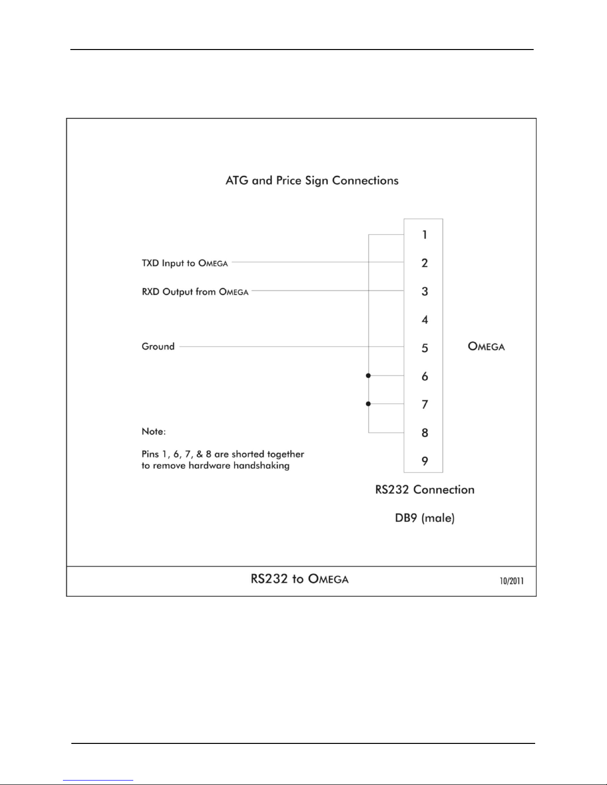
ATG & Price Signs
Referring to the RS232 to Omega Diagram, which follows, create a cable to
these specifications. Referring to the OMEGA2 Diagram – Front View, on the next
page, connect to the Auxiliary Connections Port(s). See Start-Up and
Configuration in the next section of this manual for information on logging in to
the OMEGA2web site to configure the ATG and/or price signs.
Version 1.0 October 2011
Page 5

OMEGA2/OMEGA Lite Universal Site Interface Installation Guide
OMEGA2 Diagrams
OMEGA2 Diagram – Front
View
OMEGA2 Diagram – Top View
Version 1.0 October 2011
Page 6

OMEGA2/OMEGA Lite Universal Site Interface Installation Guide
Startup and Configuration
After installing the OMEGA Lite or OMEGA2, apply power. Once the unit is initialized, the
“Ready” light on the front panel should begin blinking. This can take a couple of
minutes.
To configure the unit, connect to the Ethernet, using IP address 192.168.0.250 (default)
and port number 10010 (e.g., http://192.168.0.250:10010) The login is:
User admin
Password pie.omega2
A web page will appear. Set up the OMEGA, following online instructions. The OMEGA
Lite should be set for “Gilbarco” ONLY. The OMEGA2 should be set according to the
options installed. Enter the correct number of fueling positions for each channel of
dispensers.
Diagnostics
To access OMEGA diagnostics, use either Telnet or HyperTerminal for connectivity. Set
up a TCP/IP connection, using the configured IP address (default: 192.168.0.250) and
port 10004.
Version 1.0 October 2011
Page 7
OMEGA2/OMEGA Lite Universal Site Interface Installation Guide
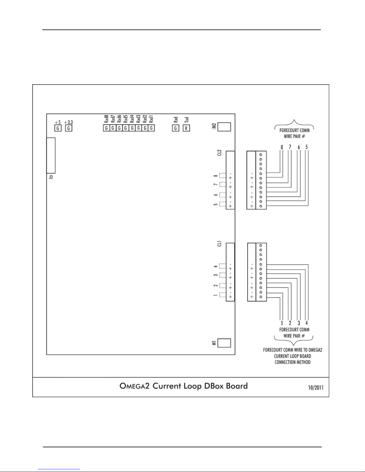
Supporting Diagrams
OMEGA2 Current Loop DBox Board
And Forecourt Comm Wire Connection Method
Version 1.0 October 2011
Page 8
OMEGA2/OMEGA Lite Universal Site Interface Installation Guide
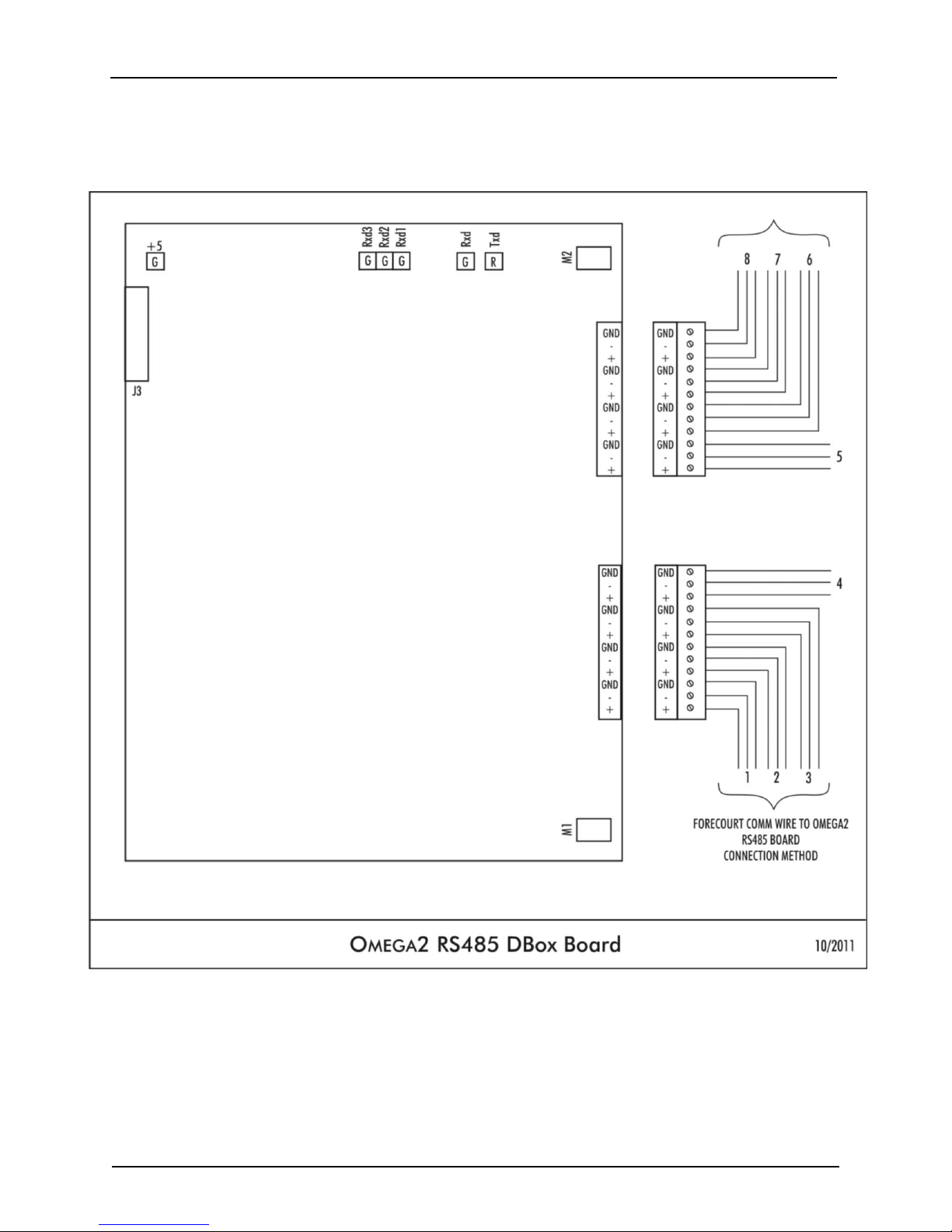
OMEGA2 RS 485 DBox Board
And Forecourt Comm Wire Connection Method
Version 1.0 October 2011
Page 9

OMEGA2/OMEGA Lite Universal Site Interface Installation Guide
OMEGA2 Tokheim DBox Board
And Forecourt Comm Wire Connection Method
Version 1.0 October 2011
Page 10
OMEGA2/OMEGA Lite Universal Site Interface Installation Guide
RS232 TO OMEGA
Version 1.0 October 2011
Page 11

OMEGA2/OMEGA Lite Universal Site Interface Installation Guide
VeriFone RS232 Adaptor
Version 1.0 October 2011
Page 12
This manual suits for next models
1
Table of contents
Popular Recording Equipment manuals by other brands

Mastervolt
Mastervolt MasterBus - Inverter Interface user manual

Barton Musical Circuits
Barton Musical Circuits Chordizer quick start guide

Freedom
Freedom Bodyworn troubleshooting guide

Worlde
Worlde PANDAMINI II user manual

Soundkitz
Soundkitz AE-F instruction manual

Wilo
Wilo DDI-I Installation and operating instructions


