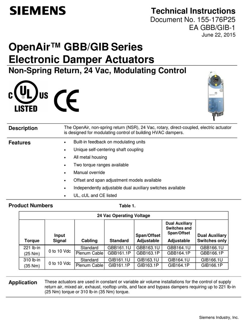
Siemens OpenAir GDE Series Owner's manual
Other Siemens Controllers manuals
Siemens
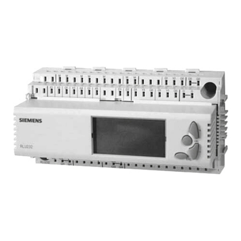
Siemens Synco 200 Operator's manual
Siemens
Siemens SINUMERIK MCU1720 Technical Document

Siemens
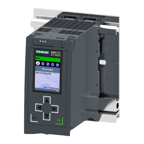
Siemens Simatic S7-1500 Instruction sheet
Siemens
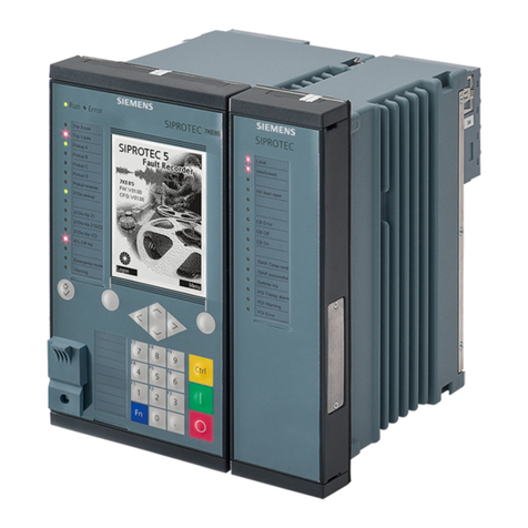
Siemens SIPROTEC 5 User manual
Siemens
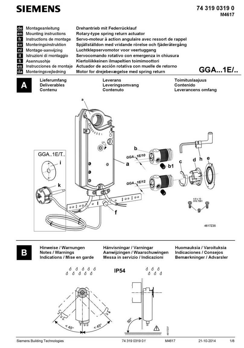
Siemens GGA 1E Series User manual
Siemens
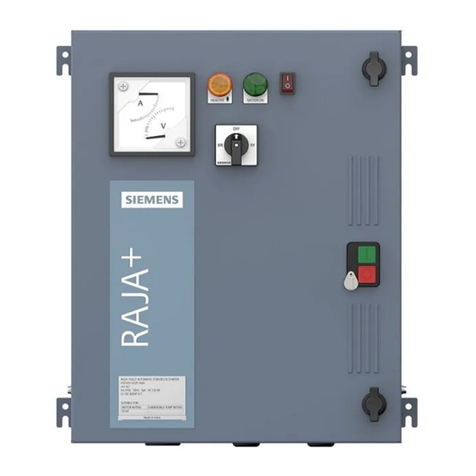
Siemens RAJA+ Operating instructions
Siemens
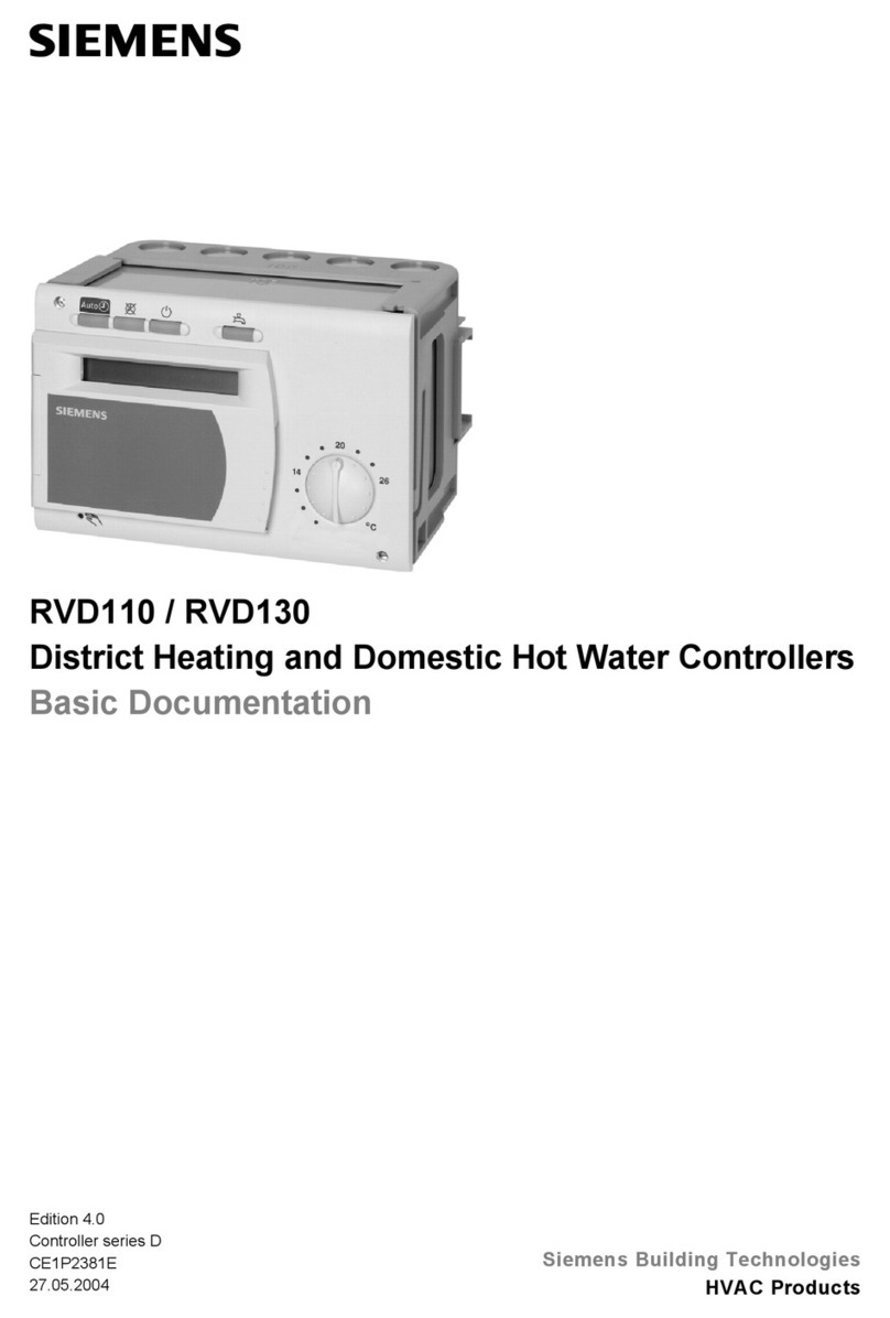
Siemens RVD110 Operator's manual
Siemens
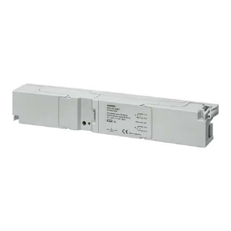
Siemens GAMMA wave GE 561/01 User manual
Siemens
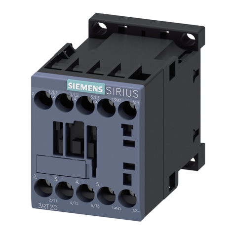
Siemens 3RT2.1.-1 User manual
Siemens
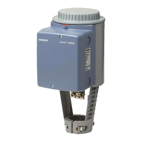
Siemens acvatix SKD32 Series User manual
Siemens
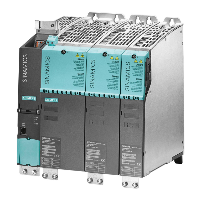
Siemens SINAMICS S120 Quick start guide
Siemens
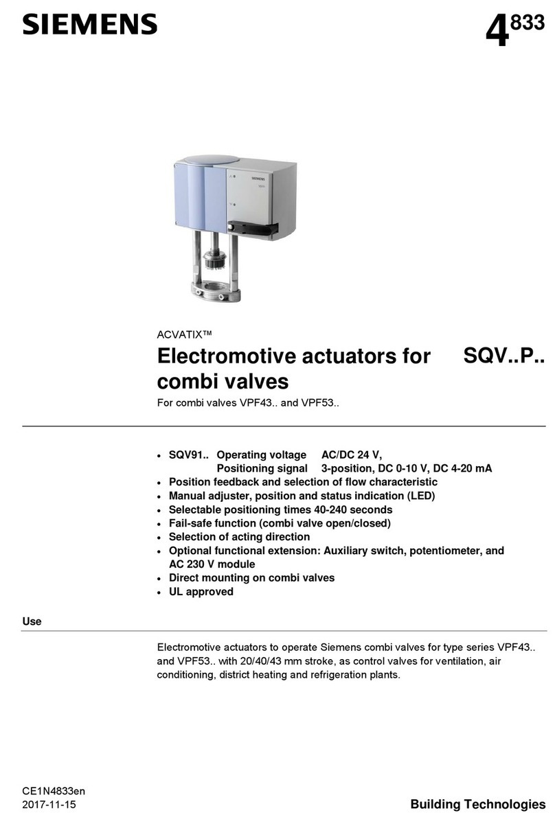
Siemens ACVATIX SQV..P Series User manual

Siemens
Siemens SINAMICS S120 Technical Document
Siemens
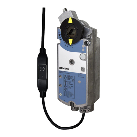
Siemens OpenAir GEB Series User manual
Siemens
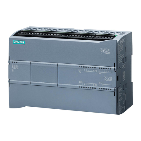
Siemens S7-1200 TELECONTROL User guide
Siemens
Siemens SINUMERIK 840D sl User manual
Siemens
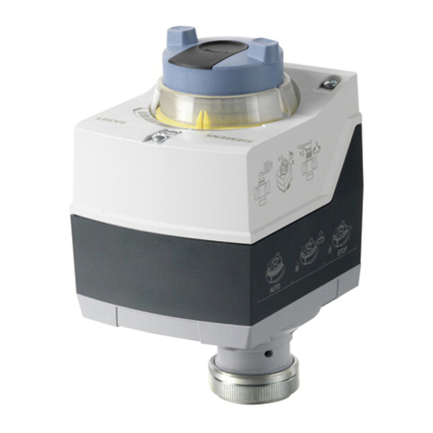
Siemens SAS61.33U Owner's manual
Siemens
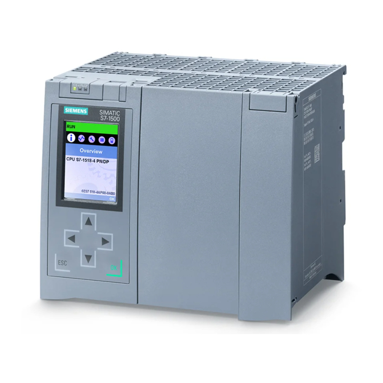
Siemens Simatic S7-1500 User manual

Siemens
Siemens SPC3 Guide
Siemens
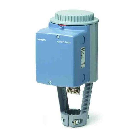
Siemens SKB32 Series User manual
Popular Controllers manuals by other brands

Digiplex
Digiplex DGP-848 Programming guide

YASKAWA
YASKAWA SGM series user manual

Sinope
Sinope Calypso RM3500ZB installation guide

Isimet
Isimet DLA Series Style 2 Installation, Operations, Start-up and Maintenance Instructions

LSIS
LSIS sv-ip5a user manual

Airflow
Airflow Uno hab Installation and operating instructions
