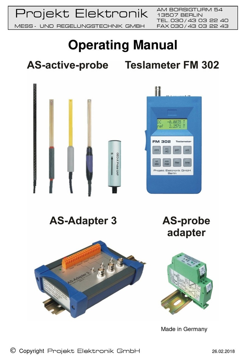
Projekt Elektronik FM 3002 User manual

Copyright Projekt Elektronik GmbH
18.07.2016
Projekt Elektronik
Mess- und Regelungstechnik GmbH
Am Borsigturm 54
135 7 Berlin / Germany
Tel. +49 3 43 3224
+49 3 43 32243Fax
Operating Manual
Teslameter FM 3002

Projekt Elektronik
MESS - UND REGELUNGSTECHNIK GMBH page 2
1. Warnings
Please read this Operating Manual carefully!
To ensure protection of the user and the instrument itself, operation of the Teslameter is permissible
only in strict accordance with the Operating Manual.
Observe personal protection rules!
When measuring magnetic fields, consider and observe the regulations concerning potential
dangers caused by DC and AC magnetic fields.
The direct influence of magnetic fields may be harmful to one's health (for field strength limits
see DIN VDE 0848).
The operation of cardiac pacemakers may be affected.
Examples for sources of potentially hazardous magnetic fields:
Ultrasonic sources magnetic resonance tomograph
Induction heaters and furnaces Medical magnetic fields
For more information see following documents:
•Electromagnetic Compatibility (Elektromagnetische Verträglichkeit),
VDE, Vol. 1 to 4
•DIN VDE 0848
•Papers of the Berufsgenossenschaft Energie Textil Elektro Mediengestaltung, Cologne
z.B. DGUV Regel 103-013 (BGR B11) – Elektromagnetische Felder

Projekt Elektronik
MESS - UND REGELUNGSTECHNIK GMBH page 3
2. Technical Advice
Please read this Operating Manual carefully!
2.1 Minimum Operation Conditions (EMC)
Measurement results may not be valid in the presence of strong RF fields (>3V/m) or burst-signals
(pulsed interferences) on the power line.
2.2 ESD
Electrostatic discharges (>0,5 kV) to any of the connectors may damage the measurement instrument.
Structural safety measures would affect measurement accuracy due to loss of sensitivity.
2.3 Radioactive Radiation
The sensor is susceptible to radioactive radiation. Exposing the probe to radiation will change the
sensitivity of the probe und thus the measured value of the magnetic field.
2.4 Ground Connection / Earthiw
2.5 ng
When mounting the probe, it should be ensured that no potential difference exists between the
protective earths (PE) of the Teslameter instrument and of the magnet. Otherwise, uncontrollable
equalizing currents may flow on the test probe cable and cause substantial damage. In certain
situations, the test probe may have to be isolated from the magnet.
2.6 Probe Connection
NEVER connect or disconnect a probe when the unit is switched ON!
2.7 Mechanical Clamping of the Probes
Should it be necessary to clamp the probe down in the area of the protective tube and not at the handle,
this MUST NOT be done within the most forward 50 mm of the probe length!

Projekt Elektronik
MESS - UND REGELUNGSTECHNIK GMBH page 4
3. Table of Contents
1.
Warnings 2
2.
Technical Advice 3
2.1
Minimum Operation Conditions (EMC).........................................3
2.2
ESD..............................................................................................3
2.3
Radioactive Radiation ..................................................................3
2.4
Ground Connection / Earthing......................................................3
2.5
Probe Connection ........................................................................3
2.6
Mechanical Clamping of the Probes ............................................3
3.
Table of Contents 4
4.
List of Figures 7
5.
Description of the Instrument 8
5.1
General Description .....................................................................8
5.2
Functional Principle......................................................................9
5.3
Items Supplied: ............................................................................9
5.4
Technical Data ...........................................................................10
5.5
Rear Panel Overview .................................................................11
5.6
Power .....................................................................................11
5.7
Probes and Probe Connector ................................................11
5.8
Ground Connection / Earthing ............................................12
5.9
Radioactive Radiation ................................................................12
5.10
Warm-up ....................................................................................12
5.11
Measuring Range.......................................................................12
5.12
Analog Output ........................................................................12
5.13
Zeroing ...................................................................................13
5.14
Zero Chamber (Option) ..............................................................13
5.15
Probes........................................................................................13
5.16
Transverse Probe ......................................................................14
5.17
Axial Probe.................................................................................14
5.18
Polarity of Measured Value ........................................................14
5.19
Remark on Precision and Repeatability .....................................15
5.20
Mechanical Clamping of the Probes ..........................................15
5.21
Typical Temperature Responses ...............................................16
5.22
Power ON ..............................................................................16
6.
Front Operation 17
6.1
Absolute and Relative Measurement: Key “Rel” and Key “Abs”.17
6.2
Integration Time and Filter: Key “Time” and Key “Filter” ............18
6.3
Units: Key “Unit”.........................................................................18
6.4
Shown Digits: Key “Digits”..........................................................19
6.5
Acoustic Feedback.....................................................................19

3. Table of Contents
Projekt Elektronik
MESS - UND REGELUNGSTECHNIK GMBH page 5
7.
RS232 Interface 20
7.1
General
.................................................................................20
7.2
Configuration of the Interface.....................................................20
7.3
Commands.................................................................................21
7.4
Relative ......................................................................................21
7.5
Absolute .....................................................................................21
7.6
Filter...........................................................................................22
7.7
Time or Inttime ...........................................................................22
7.8
Unit.............................................................................................22
7.9
Digits ..........................................................................................23
7.10
Status or FM Status ...................................................................23
7.11
Default........................................................................................23
7.12
Externcalibration ........................................................................24
7.13
Logging ......................................................................................24
7.14
Sound.........................................................................................24
7.15
Keys...........................................................................................25
7.16
Version.......................................................................................25
7.17
HyperTerminal under Microsoft Windows Vista .........................25
8.
Controlsoftware for FM 3002 26
8.1
FM3002Control v 1.0..................................................................26
8.2
General Description ...................................................................26
8.3
Installation..................................................................................26
8.4
Usage.........................................................................................27
8.5
Uninstall .....................................................................................27
8.6
Source Code ..............................................................................27
9.
Maintenance and Warranty 28
9.1
Visual Inspection........................................................................28
9.2
Cleaning.....................................................................................28
9.3
Maintenance ..............................................................................28
9.4
Warranty ....................................................................................28
10.
Calibration 29
10.1
General ......................................................................................29
10.2
Factory Calibration.....................................................................29
10.3
Custom Calibration.....................................................................29
11.
Customer Service 30
11.1
Repair ........................................................................................30
11.2
Follow-Up Orders.......................................................................30
11.3
Disposal .....................................................................................30
12.
EU Declaration of Conformity 31

3. Table of Contents
Projekt Elektronik
MESS - UND REGELUNGSTECHNIK GMBH page 6
13.
Index 32
FM 3002 0207-18.docx

Projekt Elektronik
MESS - UND REGELUNGSTECHNIK GMBH page 7
4. List of Figures
Fig. 1: Teslameter FM 3002............................................................... 8
Fig. 2: structural construction of Teslameter FM 3002....................... 9
Fig. 3: rear panel of the instrument .................................................. 11
Fig. 4: zero chamber ........................................................................ 13
Fig. 5: transverse probe ................................................................... 14
Fig. 6: axial probe ............................................................................ 14
Fig. 7: definition of polarity ............................................................... 14
Fig. 8: Trigonometric of the measuring arrangement ....................... 15
Fig. 9: typical temperature responses .............................................. 16
Fig. 10: display with keys ................................................................. 17
Fig. 11: window FM3002Control ...................................................... 26

Projekt Elektronik
MESS - UND REGELUNGSTECHNIK GMBH page 8
5. Description of the Instrument
Fig. 1: Teslameter FM 3002
5.1 General Description
The Teslameter FM 3002 is a high-precision and extremely temperature-independent instrument for
magnetic flux density measurement.
The display is digital - 7½ digits - and requires no temperature or correction tables which means one
can resolve 1 800 000.0 µT to 0.1 µT. Better accuracy would be possible only by using the proton
resonance method (NMR), which is time-consuming and cannot be used in just any situation.
As a speciality, the FM 3002 has not only a highly accurate and stable display but also an enhanced-
accuracy analog output, which makes possible the use of the instrument as a high-accuracy
measuring transducer.
Several correction processes, some of which intervene up to 20,000 times per second, are used to
take into account and correct the non-linearities and the complex temperature dependencies of the
Hall element in each individual probe.
Each instrument can be shipped ex works including the individual correction data of any two probes
(transverse or axial) so that two different probes can be used on it by simply plugging them out and in.
The transverse and axial probes both have the same accuracy of typ. 0.01 % of reading ± 0.005 % of
range with a temperature coefficient of 5 ppm/K (<0.0005 %) at 25 °C.
Optional a probe extension cord up to 27 m is available. This can be plugged between probe and
device, if a larger distance between measured object and measuring instrument have to be covered.
The influence of the probe extension cord to the measured value is very low. An additional calibration is
not necessary. However we recommend to omit the application of a probe extension cord where
possible. With optimal accuracy and low electromagnetic susceptibility in mind it is more appropriate to
extend the analog output or the RS232 interface.
Nuclear magnetic resonance (NMR) is used as a reference standard.
Outstanding performance data like these establish the FM 3002 as a top-of-the-class measuring
instrument. Each unit is shipped with a factory calibration certificate stating traceability to national
reference standards. Re-calibration is recommended in one-year intervals.
The FM 3002 has a 2 HE-19’’ housing. As desktop version it is equipped with stands, as rack version it
comes without stand but with mounting brackets.

5. Description of the Instrument
Projekt Elektronik
MESS - UND REGELUNGSTECHNIK GMBH page 9
5.2 Functional Principle
Fig. 2: structural construction of Teslameter FM 3002
The graphic shows the simplified structural construction of the Teslameter FM 3002. To achieve the
outstanding accuracy of the device a multitude of parameters is incorporated. In the graphic thereof
are only shown the measurement of the probe temperature and the actual value of the probe signal.
The generated corrections directly affect to the analog signal path. This principle offers considerable
advances against solely digital correction techniques. At solely digital correction techniques first the
probe signal is digitized with an analog-to-digital converter, corrected at the digital level and then again
putted out as an analog signal via a digital-to-analog converter. Due to the restricted resolution of the
converter it is inevitable that steps occur in the output signal. In contrast the Teslameter FM 3002 with
its principle generates a continuous signal response.
The analog output of the Teslameter FM 3002 is directly feed from the corrected signal and therefor
provides full correction and yet a bandwidth of 100 Hz.
Eventually the corrected high precision analog output is sampled with a high-resolution analog-to-digital
converter. Out of it the values for the digital display and the serial port are obtained. The settings for
integration time and filter affect only the digital path. The program for relative measurement is also
generated in the digital path. The analog output is not affected by these settings.
5.3 Items Supplied:
1 Teslameter FM 3002 1 factory calibration certificate
1 probe in a probe case 1 operating manual
1 power cord 1 CD with software examples
1 RS 232 cable 10 m 1 zero chamber (option)
1 probe extension cord (option)
probe
correction
generation
J
analog output
1.234567 TADC digital
filter
100 Hz
digital display

5. Description of the Instrument
Projekt Elektronik
MESS - UND REGELUNGSTECHNIK GMBH page 1
5.4 Technical Data
Range: ± 1.800 000 0 T ± 1.800 000 0 V analog output
± 1 800 000.0 µT 7½-digit display
Non-linearity (incl. probe) 0.01 % of reading, ± 0.005 % of range
(at 23 °C; 50 mT – 1.8 T)
Resolution (display) 0.1 µT (1/18 000 000)
Temperature coefficient instrument 3 ppm/K (0.0003 %/K)
Temperature coefficient probe at 25 °C
probe T; A 5 ppm/K (0.0005 %/K)
Zero drift 2 µT/K
Long-time stability 0.1 % / year (typ. 0.05 %/year)
Bandwidth 0 - 100 Hz (– 3 dB) analog output
DC display
Noise 0.5 µT
eff
(0 - 1 Hz)
Display units µT, mT, T, G, kG
Measuring time 0.1 s to 5 s
Probe size 9 x 2.5 x 200 mm transverse probe T 1
Ø 8 x 200 mm axial probe A 1
2.80 m probe cable
Effective area 1.5 mm x 3.0 mm transverse probe
0.8 mm axial probe
Operation temperature +10 °C to +40 °C
Storage temperature - 20 °C to +50 °C
Relative humidity 70 % at +35 °C
Size housing (W x H x D) 449 x 104 x 320 mm desktop version
483 x 89 x 320 mm 19“ rack version
Power 115 V, 230 V±10 % / 50 Hz - 60 Hz / 20 VA
Pollution 2 under IEC664
Protection Class I
Weight 4.50 kg
Probe Extension Cord
additional error ±(10 µT + 10 ppm) (cord length 15 m)
Technical data are subject to change without prior notice!

5. Description of the Instrument
Projekt Elektronik
MESS - UND REGELUNGSTECHNIK GMBH page 11
5.5 Rear Panel Overview
Fig. 3: rear panel of the instrument
probe connector
mains socket
zero point trimmer ‘Zero’
power switch
analog output
connector protective earth
RS232 connector
connector analog ground
5.6 Power
The FM 3002 is operated on 230 V or 115 V AC power.
The operating voltage is selected by plugging the corresponding fuse adaptor into the power outlet.
The selected voltage will be displayed in the fuse adaptor as being 230 V or 115 V. Instrument
operation is possible with both 50 Hz and 60 Hz.
The fuse holder on the power switch houses two medium-blow 0.315 A / 250 V fuses (M 0.315/250).
For 115 V operation, the fuses should be replaced by medium-blow 0.63 A units.
If operating the mains switch does not result in the digital display lighting up, these fuses should be
checked.
5.7 Probes and Probe Connector
Two probes of any kind (axial and/or transverse) can be provided for each Teslameter unit.
Each probe is marked at its plug end with the serial number of the associated instrument (nameplate
on the rear panel of the FM 3002); in situations where several FM 3002 are used, this ensures the use
of each together with the correct probe only.
The 25-position probe plug is plugged into the 25-position receptacle "Probe" and the two retaining
screws in the plug are tightened.
NEVER connect or disconnect a probe when the unit is switched ON!

5. Description of the Instrument
Projekt Elektronik
MESS - UND REGELUNGSTECHNIK GMBH page 12
5.8 Ground Connection / Earthing
The PE (protective earth) conductor of the power supply is connected to the instrument case.
The analog ground is connected to PE through 1 MOhm || 22 nF.
The voltage between PE and analog ground must not exceed ± 39 V.
Two terminals (black for analog ground and yellow-green for PE) enable the analog ground to be
connected directly to PE.
When mounting the probe, it should be ensured that no potential difference exists between the
protective earths (PE) of the Teslameter instrument and of the magnet. Otherwise,
uncontrollable equalizing currents may flow on the test probe cable and cause substantial
damage. In certain situations, the test probe may have to be isolated from the magnet.
5.9 Radioactive Radiation
The sensor in the probe of the Teslameter FM 3002 is a hall element. This sensor is susceptible
to radioactive radiation. There is some shielding through the brass material of the probe. But
exposing the probe to radiation will change the sensitivity of the probe und thus the measured
value of the magnetic field.
5.10 Warm-up
Several components must have reached their rated operating temperature before the instrument
reaches its full accuracy and temperature stability.
Almost all performance data specified will be met approx. 10 min after power turn-on.
For highly accurate repeatable measurements with a < 100 µT tolerance, a warm-up phase of approx.
30 min should be observed.
5.11 Measuring Range
The measuring range is ± 1.8 T .
Exceeding the display range of approx. ± 2.3 T causes the message "!OVERLOAD!" to appear on the
display.
The measuring range of the FM 3002 is specified to have an accuracy of ±0.01 % of reading up to
1.8 T and of ± 0.01 % of the range (2 T).
For flux densities higher than 1.8 T, the displayed value or output voltage is still proportional, although
with a higher error of approx. 1 - 3 %.
5.12 Analog Output
The analog output "out" (BNC female connector on the rear panel) offers a highly accurate, stable,
low-noise voltage signal highly proportional to the value of the measured flux density with the ration
1.000 000 0 V ≡1.000 000 0 T.
This voltage can be used as flux density value in field control or for analog field scanning and
detection.
The output is short-circuit proof with an internal impedance ≤1 Ohm.
To take advantage of the high accuracy (± 0.01 % of reading, ± 0.005 % of range), the input
impedance of the connected evaluation electronics should be > 20 kOhm.
The bandwidth of the output signal is limited to 100 Hz (-3 dB).

5. Description of the Instrument
Projekt Elektronik
MESS - UND REGELUNGSTECHNIK GMBH page 13
The analog output is independent on relative measurement. It provides the instantaneous absolute
flux density value at any time.
5.13 Zeroing
The highly stable electronics of the FM 3002 and the many probe data it has stored in memory ensure
a zero setting which is precise and stable and easily repeatable.
Still, the zero setting should be checked and reset, if necessary, after some time.
To this end, the probe is introduced in a zero chamber; the instrument will show whether the zero
setting should be readjusted.
This can be done - for each of probes 1 and 2 separately - by means of the "zero" slotted trimmer
potentiometer on the rear panel of the FM 3002.
The zero setting should be checked also whenever the probe is changed.
Zeroing should not be carried out before an approx. 30 min warm-up period has elapsed.
5.14 Zero Chamber (Option)
Optional a zero chamber is attainable for our instruments.
The zero chamber is a one side closed pipe of good magnetic shielding metal to shield the existing
outer field. That is at least the earth magnetic field. In addition there may be other interfering fields from
the environment. In real world shielding may not be 100 %. A small residual magnetic field remains
inside of the zero chamber.
Fig. 4: zero chamber
5.15 Probes
Two different types of probe are offered: an axial probe and a transverse probe .
The connecting cable comes with a length of 2.80 m. Lengths up to 25 m are possible on demand.
Lengths greater than 2.80 m do not affect the accuracy and temperature specifications as the
instrument will be calibrated with the longer cable, so that the same high precision can be guaranteed.

5. Description of the Instrument
Projekt Elektronik
MESS - UND REGELUNGSTECHNIK GMBH page 14
5.16 Transverse Probe
Dimensions (mm): L = 200 D = 9.0 C = 2.5 A = 4 ±1
Active area (mm): 1.5 x 3.0
A
D
C
Ø11
L
100
+B
Fig. 5: transverse probe
5.17 Axial Probe
Dimensions (mm): L = 200 D = 8.0 A = 2 ±0.5
Active area (mm): Ø 0.8
Fig. 6: axial probe
5.18 Polarity of Measured Value
On the transverse probes, the center of the active area is marked by a „ + “ symbol. On Axial Probes,
that center lies on the central probe axis.
If the magnetic flux density vector enters the measuring probe through the „ + “ symbol, the value
displayed will be positive (Fig. 7: definition of polarity). As memory hook one can think about an arrow,
which when seen from behind is a cross. Positive indicated values mean the field is in the direction of
the arrow.
For transverse probes, the reading at the analog output and on the display relates to a vector entering
the probe at 90° to the surface of the probe profile.
+B
I
f
Fig. 7: definition of polarity

5. Description of the Instrument
Projekt Elektronik
MESS - UND REGELUNGSTECHNIK GMBH page 15
5.19 Remark on Precision and Repeatability
The flux density is a vector. To measure the exact value, the probe has to be positioned exactly
perpendicular to the flux direction. If the lines of magnetic force do not enter the Hall element at right
angle, the displayed value results from the true magnetic flux density according to the following relation:
B = B
max
•cos α
Fig. 8: Trigonometric of the measuring arrangement
For example to measure a flux of 1 T with precision of 0.1 µT the deviation of the angle have to be
less than two arc minutes. For illustration: On a rotation with radius 100 mm this relates to a distance
of only 0.3 mm.
The repeatability of the measurement extremely depends on the quality of the mechanical clamping of
the probe.
The main reason to use a high-precision teslameter is not the absolute precision rather than the long
term stability and the reliability in differential measurement.
5.20 Mechanical Clamping of the Probes
Transverse and axial probes are housed in a protective brass tube so as to maximize the protection
for the Hall element.
Should it be necessary to clamp the probe down in the area of the protective tube and not at
the handle, this MUST NOT be done within the most forward 50 mm of the probe length!

5. Description of the Instrument
Projekt Elektronik
MESS - UND REGELUNGSTECHNIK GMBH page 16
5.21 Typical Temperature Responses
Fig. 9: typical temperature responses shows the temperature responses and error limits within the 10
to 40 °C temperature range for fields of + 0.8 T and – 0.8 T.
Fig. 9: typical temperature responses
5.22 Power ON
After the probe has been plugged in, the instrument can be turned ON using the power switch on the
rear panel. The digital display lights up.
With the probe located in a space with a magnetic field of a magnitude equivalent to the Earth's
magnetic field (approx. ± 50 µT), the display will show that.
0,8 T
-0,15
-0,1
-0,05
0
0,05
0,1
0,15
10 15 20 25 30 35 40
°C
mT
-0,8 T
-0,15
-0,1
-0,05
0
0,05
0,1
0,15
10 15 20 25 30 35 40
°C
mT

Projekt Elektronik
MESS - UND REGELUNGSTECHNIK GMBH page 17
6. Front Operation
Fig. 10: display with keys
The display shows the magnetic flux as number and unit. Different settings allow the variable
adjustment to varying measurement tasks.
6.1 Absolute and Relative Measurement: Key “Rel” and Key “Abs”
After power-on the unit is in absolute mode. Positive and negative values will be displayed. See also
“Polarity of Measured Value”.
The upper display row shows the true flux density measured by the probe. By pressing the key “Abs”
one can switch to absolute mode at every time.
By pressing the key “Rel” the actual absolute value is saved as reference and showed at the lower part
of the display. At the upper part the relative value referred to the saved reference value is shown
marked with ““.
relative value = actual absolute value – reference value
Pressing “Rel” again sets the actual absolute value as new reference value (lower display line).
See also chapter 3 Serial Interface for other possibilities of relative and absolute measurement.
The relative mode has no effect on the analog output of the FM 3002. The analog output always
provides the actual absolute value.

6. Front Operation
Projekt Elektronik
MESS - UND REGELUNGSTECHNIK GMBH page 18
6.2 Integration Time and Filter: Key “Time” and Key “Filter”
The key “Time” sets the integration time. According to that the refresh rate of the display is set, which
means that after expiration of the integration time a new value is displayed.
The internal sampling rate is 10 Hz.
With the key “Time” one can chose the integration times from the below-mentioned table. Out of it
results the number of samples used for averaging.
TIME 100 ms
200 ms
500 ms
1 s
2 s
5 s
averaged Samples 1 (off)
2
5
10
20
50
A short key press shows the actual integration time at the display. With successive presses the
integration time is raised cyclically. Every successive press has to be done within 0.8 s or it will be
taken again as a first press.
The key “Filter” allows the filtering about a selectable number of values. Therefor a built-in digital filter
is used. The table shows the selectable filter lengths.
FILTER 1
2
4
8
16
32
64
After a fast change of flux it is advisable to wait Filter x Time before using the measured value.
A short key press shows the actual filter length at the display. With successive presses the filter length
is raised cyclically. Every successive press has to be done within 0.8 s or it will be taken again as a
first press.
See also chapter 3 Serial Interface for other possibilities of setting integration time and filter length..
6.3 Units: Key “Unit”
The key “Unit” sets the unit for the displayed values. The table shows the selectable units.
UNIT µT
mT
T
Gs
kGs
Every key press selects cyclically the next unit.
Exception: see chapter 2.4
See also chapter 3 Serial Interface for other possibilities of setting integration time and filter length.

6. Front Operation
Projekt Elektronik
MESS - UND REGELUNGSTECHNIK GMBH page 19
6.4 Shown Digits: Key “Digits”
The key “Digits” allows to hide decimal places which will replaced by a underscore. Here the value is
rounded mathematically correct. The use of this function does not interfere with the precision of the
FM 3002 in any way. It is only a reading simplification.
Every key press hides one more decimal place up to maximal four places.
example with 1.2345678 T:
key press
display
0
1.2345678 T
1
1.234568_ T
2
1.23457__ T
3
1.2346___ T
4
1.235____ T
5
1.2345678 T
…
…
The using of the key “Digits” has a anomaly. To avoid misunderstandings only decimal places can be
blinded out. If there are not enough decimal places the error message “More decimal places needed” is
displayed.
Double-pressing results in the next possible selection. The same applies to the key “Unit”.
See also chapter 3 Serial Interface for hiding the decimal places.
6.5 Acoustic Feedback
Every new setting is acknowledged acoustically by a two-tone. At an error message the feedback is a
disharmonic tone.
See also chapter 3 Serial Interface for switching acoustic feedback on and off

Projekt Elektronik
MESS - UND REGELUNGSTECHNIK GMBH page 2
7. RS232 Interface
7.1 General
All functions to be served at the key-pad can be controlled remotely via the RS232 interface.
Furthermore, there are extended and additional commands.
Every ordinary terminal or terminal program can used to communicate with the FM 3002. The control is
text-oriented thereby it can easily integrated in existing environments.
The terminal program should use a font which contains the “µ”-sign for display.
Unfortunately HyperTerminal under Microsoft Windows does not do that by default. Here the font should
be switched to Courier New or Fixedsys.
7.2 Configuration of the Interface
For communicating with the FM 3002, the RS232 interface should be configured as follows:
baudrate 9600
databits 8
parity none
stopbits 1
flow control none
To connect the FM 3002 with an IBM-compatible PC a serial cable (1:1) has to be used. Important are
only the lines TXD, RXD and GND. The other lines are not used.
Common USB to RS323 converter have the correct pinout and can be used without further addon. Due
to the great variety of offered converters a general functioning guarantee can not be given.
8
TxD
RTS
CTS
RxD
TxD
RTS
CTS
RxD
GND
GND
FM 3002 PC/terminal
DTR
DSR
3
2
5
8
7
3
2
5
7
6
4
D-Sub, 9-pol., female connector D-Sub, 9-pol., male connector
6
4
DTR
DSR
Table of contents
Other Projekt Elektronik Measuring Instrument manuals
