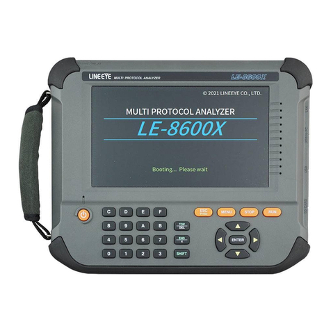
LineEye LE-8600XR User manual

《Ver.6 2023.03 》
MULTI PROTOCOL ANALYZER
INSTRUCTION MANUAL


-1-
2022 by LINEEYE CO., LTD. All rights reserved
Instruction
Thank you for your purchase of LE series.
To use it correctly, you are advised to read and understand this instruction manual thoroughly. Keep
this together with the warranty. If you encounter any problems, you will nd helpful information in
this manual.
NOTICE
It is prohibited to reprint or duplicate any part of the whole of this instruction manual without
prior permission from LINEEYE.
The content of this instruction manual and specications of the products are subject to change
without any notice.
This instruction manual has been designed and edited with great care to give you all necessary
information. If you have any questions, feel free to direct your inquiries to LINEEYE.
LINEEYE makes no warranty or guarantee, either expressed or implied with respect to its
quality, performance, merchantability, or tness for a particular purpose. LINEEYE shall not be
liable for direct, indirect, special, incidental, or consequential damages resulting from any defect
in the product. The warranty and remedies set forth above are exclusive and in lieu of all others.
USER LIMITATION
This product has not been developed for the use that needs exclusively high reliability and
safety: aerospace apparatus, trunk communication apparatus, nuclear control apparatus, medical
apparatus related with life maintenance etc. Therefore, do no use for those purposes.
LE-series models with Wi-Fi function (IEEE 802.11b/g/n) emit radio wave. Please do not use it
near a medical device, microwave, high-level electronics, TV, radio, wireless station for mobile
communication, or specified low power radio station. To use LE-series in the place where an
administrator limits the use of radio devices, follow the instruction of the administrator.
The Wi-Fi module used for the LE-series conforms to SRRC(China), FCC (USA), CE (EU),
TELEC (Japan), KCC (Korea), ISED (Canada), NCC (Republic of China), however, as its product
(LE-series) the Wi-Fi function is available only in Japan, USA, Canada, and EU nations in
compliance with RE directive (2014/53/EU).
To use the product other than above countries, order LE-series without Wi-Fi function. Please
contact the sales department for more details.
= = = Notice = = =
This product contains a battery.
To keep the quality of the battery, LINEEYE does not fully charge the battery.
Before using the battery, please make sure to charge the battery. When you
dispose of it, please follow the regulation of the region.

-2-
Read this rst !!
This Safety Information includes the following important information in order to not only have
you learn the right way to use the analyzer, but also prevent you from causing damage to people
and property. Before using,
please read the main contents after you understand the following symbols & marks.
Should the device be used without following these symbols, there is a
possibility of accidents, such as a death or a serious injury, occurring.
Should the device be used without following these symbols, there is a
possibility of accidents, such as a injury (*1), and material damage (*2)
occurring.
*1 :“Injury” indicates injury, burn and electric shock, or the like which
does not require hospitalization or the extended hospital visit.
*2 :“Material damage” indicates damage related to a house, a building,
furniture, apparatus, livestock or a pet.
Prohibition The necessary
● Do not disassemble, modify or repair the line monitor
This may result in an injury, electric shock, and ignition.
● Turn o the power of analyzer and unplug the cables immediately when emanating
smoke, odor or sound.
Continuous use may result in an electric shock, injure or ignition.
● Do not use the line monitor if there is inammable gas.
This may result in ignition and explosion.
● Turn o the power and unplug the line monitor immediately when liquid or foreign
substance gets into the line monitor.
Continuous use may result in ignition, electric shock and malfunction.
● Do not touch the line monitor with wet hand.
This may result in an electric shock and malfunction.
● Do not use the battery other than attached Lithium ion battery. Do not short the
electrode of the battery. Do not modify, decompose or heat the battery
It may cause the ignition and explosion.
● Do not give a strong impact on the product, such as dropping and crashing.
Safety Information
War ning
Caution
War ning

-3-
● Please follow the instruction for the USB Battery Charger. It may cause the
generation of heat, injure, electric shock and malfunction
・Do NOT use it for other than AC 100V to 240V.
・Do no use when it brakes.
・Do not twist or step on the cable of charger.
(Do not stress the base of cable.)
・ Do not place near the heater or put in the re.
・Do not disassemble, modify the USB Battery Charger or cable.
・Do not curve the cable around the USB Battery Charger.
・Do not put many loads on one electrical outlet.
・Insert it well to the electrical outlet.
・Remove the dust on the AC plug.
・Unplug the charger if you do not use it.
・When unplugging from the outlet, pull out the body straight.
● Do not leave the analyzer in the following conditions.
・ Strong magnetic eld, static electricity or dusty place.
・ Temperature and humidity above the specication or where dew condensation
appears.
・ Not at, or shaking place.
・Place with leaking water or electricity.
・ Place aected by direct sun or near the re.
Please do not leave the analyzer in the car during the summer.
● Do not use at the following situations. The radio wave by the analyzer may cause
trouble.
・Near a medical device such as cardiac pacemaker or hearing aid.
・ Near an automatic controller such as re-alarm box or automatic door.
・Near a microwave, high-level electronics, TV, or radio.
・ Near a wireless station for mobile communications or a specied low power
radio station.
Remove the battery from the analyzer, when you throw away.
Caution
Caution

-4-
CONTENTS
Instruction ................................................ 1
Safety Information 2
Chapter 1 Before Using the Product 6
1.1 Description on This Manual .............. 6
1.2 Unpacking .......................................... 6
1.3 Functions and Feature........................ 7
1.4 Name of Each Part.............................. 9
1.5 Power Supply and Battery................. 13
1.6 Hand Strap......................................... 15
1.7 SFP module........................................ 16
Chapter 2 Basic Operation and Set-up17
2.1 Power Source ON (Opening Screen) 17
2.2 Top Menu .......................................... 18
2.2.1 File Manager ................................. 19
2.2.2 Record Control.............................. 19
2.2.3 System Cong................................ 23
2.2.4 Time Settings............................... 27
Chapter 3 Online Monitor Function 28
3.1 Connection ........................................ 28
3.2 Interface Setup .................................. 29
3.3 Filter Setup ........................................ 30
3.4 Online monitor Conguration .......... 34
3.5 Start and Stop Measurement............ 36
3.6 Display............................................... 37
3.7 Retrieval Function............................ 41
3.8 Trigger Function............................... 43
Chapter 4 SFP Module Information
Display Function 45
4.1 Connection method ........................... 45
4.2 Information display........................... 45
Chapter 5 Statistic Function 46
5.1 Connection ........................................ 46
5.2 Frame Counters ................................ 46
5.3 Statistical analysis settings .............. 46
5.4 Start and Stop Measurement............ 47
5.5 Display............................................... 47
Chapter 6 Packet Generator Function 48
6.1 Connection ........................................ 48
6.2 Transmission settings ....................... 48
6.3 Transmission packet summary......... 48
6.4 Editing the transmission packets...... 49
6.5 Start and Stop Testing....................... 53
6.6 Test Result ......................................... 53
Chapter 7 Ping Function 54
7.1 Connection......................................... 54
7.2 Ping Setup ........................................ 54
7.3 Start and Stop Testing ....................... 55
7.4 Display ............................................... 55

-5-
Chapter 8 Port Blink Function 56
8.1 Connection ........................................ 56
8.2 Searching Hub port ........................... 56
Chapter 9 Save and Load of the Data 57
9.1 Storage device ................................... 57
9.2 File Management Function ............... 58
Chapter 10 Utiltty 64
10.1 Key Emulation Software................. 64
10.2 Data Conversion Software .............. 65
10.3 Capture data les while measuring 67
10.4 PC Remote Control Library ............ 68
Chapter 11 Printout Function 69
11.1 How to Connect to a Printer............ 69
11.2 Hard Copy of Screen Display.......... 69
11.3 Printout of Measurement Data ....... 70
Chapter 12 Specications and
Maintenance 71
1 2 . 1 S p e c i c a t i o n s o f F u n c t i o n a n d
Hardware.. 71
12.2 Shortcut Keys.................................. 72
12.3 Measurable Interface Expansion .... 73
12.4 Factory reset .................................... 73
12.5 Firmware Update ............................ 74
12.6 Trouble shooting.............................. 75
12.7 Warranty and After service ............ 77

-6-
1.1 Description on This Manual
Function for dierent model
・When the performance or function diers depending on the model of the protocol analyzer,
[Model number] is described side by side.
Deception of the Operating Procedure
・Printed representation of screen displays in the manual may not be the same as that actually
displayed concerning the font and special symbols.
・ Descriptions of items of the screen are enclosed in double quotation marks “ ” .
・Reference page is described with .
・Represent key is enclosed in [ ].
e.g. Press “ ” key. : Press [MENU].
・Successive key or tap operations may be represented by putting their symbols one after another.
e.g. Press [MENU], then press [0]. : Press [MENU] -> [0].
e.g. Tap [A], then tap [B]. : Tap [A] -> [B].
・ Pressing two keys at the same time is represented by combining their symbols with “+” .
e.g. Press [SHIFT] and [ESC] at the same time : Press [SHIFT]+[ESC].
Chapter 1 Before Using the Product
1.2 Unpacking
When you unpack the product, check the items below:
■The product has not been damaged during the transit.
■You have received all the standard accessories listed below.
□ Protocol Analyzer 1
□ Interface Sub-board [SB-10GE] (attached to the analyzer) 1
□ Hand strap ( Already mounted) 1
□ Wide input AC adapter (input: AC100 to 240V, output: DC9V)1
□ LAN cable 1
□ USB cable (Type A - Type-C) 1
□ External signal I/O cable [LE-4TG] 1
□ Utility CD 1
□ Quick Start Guide 1
□ Carrying bag [LEB-01] 1
□ Registration card, Warranty 1
The card packed with the product is the user registration card for Japanese customers.
For overseas customers, there is a user registration page on our web site.( https://www.
lineeye.com )
Please let us know if you nd any damage to the product or accessories lacking.

-7-
1.3 Functions and Feature
The LE-8600X/LE-8600XR are equipped with two measurement ports compatible with SFP/SFP+
modules and are handy type Ethernet LAN analyzer that supports high-speed LAN measurement tests
that use single-mode or multi-mode optical ber cables as a single unit. You can log the data automatically
to the built-in 500GB SSD. As it has the online monitor function, packet generate (PG) function,
statistical analysis function etc. you can use the analyzer according to the test situation. It can be widely
used for communication systems, communication device development, inspection, and failure diagnosis.
♦On-line Monitor Function
This function records both the Ethernet communication frame owing through the network and
the transmission/reception time (timestamp) of the frame.
♦Statistic Function
This is a useful feature for analyzing network trac and the frequency of specic frames.
♦SFP module information display function
You can display the detailed information of SFP/SFP+ modules.
♦Packet Generator(PG) Function
You can transmit any packet.
♦Ping Function
It is able to conrm the linking to the network by transmitting the Ping commands.
♦Port Blink Function
You can see which port on the hub the multiple Ethernet cables are connected to.
♦Utility CD
Utility CD contains following les
Manual folder : Instruction manual for the analyzer
Utility folder : Utility software to convert measurement les to Wireshark format
Key emulation software

-8-
Optional Accessories
・1000BASE-T SFP module LE-1G-BT-45
・1000BASE-SX SFP module LE-1G-SX-85
・1000BASE-LX/LH SFP module LE-1G-LX-31
・10GBASE-T SFP+ module LE-10G-BT-45
・10GBASE-SR SFP+ module LE-10G-SR-85
・10GBASE-LR SFP+ module LE-10G-LR-31
・Expansion kit for Gbit Ethernet LAN SB-GE2
・Expansion kit for RS-232C/530/422/485/TTL communication SB-R2TS1
・GPS active antenna EB-SL-AA170
・Coaxial cable for PPS synchronization LE-SMA-MM-2
・LAN cable
・Lithium ion battery pac P-26LW2
・8Gbyte SDHC card SD-8GX
・16Gbyte SDHC card SD-16GX
・32Gbyte SDHC card SD-32GX
・ Portable thermal printer SM4-31W
Features
・Two measurement ports which support SFP/SFP+ modules
・Real-time monitor recording of 10Gbit packets
・Output test packets for network load test
・Adds time stamps which can be synchronization by GNSS (PPS) signal
・Automatically records communication logs into the internal SSD
・Newly designed lightweight housing with 7-inch color LCD with touch panel
・ Save data in PcapNG les that can be analyzed by Wireshark
・PC link with LAN, USB, or Wi-Fi (XR only) connection

-9-
1)
2)
3)
4)
7)
8)
9)
10)11)
5)
6)
12)
16)
17)
13)
14)
15)
1.4 Name of Each Part
General
Name Description
1) AC adapter plug Connects the AC adapter, which serves as a battery charger.
2) Power Switch Press for about 1 second to turn the power on/o.
3) SD Card Slot The inlet for a SD/SDHC card.
4) USB Host Port Connection port for a USB ash drive or Printer.
5) USB Device Port USB Type-C connector connected to a PC or battery charger.
6) Wired LAN
Connect to a computer via Ethernet LAN.
The right LED lights in green when linking. The left LED lights in
orange when 1000BASE-T is connected.
7) Interface Sub-Board The interface sub-board (SB-10GE) for measuring of 10GbE is inserted.
Able to exchange to the optional interface sub-boards.
8) PORT A,B Insert SFP/SFP+ modules for various measurement.
1.7 SFP module
9) External Input Terminal Input/output terminal for TTL level external signal.
3.8 Trigger Function EXT TRG Enable

-10-
LED and Display
■Power LED
Light in green during operation. Blink in red while it charges a battery.
Slow charge (when AC adapter is connected)
: Blink per 1 sec.
Normal charge (when connected by USB Type-C) : Blink per 1.5 sec.
Fast charge (when connected via other USB) : Blink per 4 sec.
1.5 Power Supply and Battery
■Line state LED
Tap “LED” at the bottom right of the screen to display the meaning of each LED.
If you tap anywhere in the area while it is displayed, it will be hidden.
You can also switch shown/hidden the display of the meaning of each LED by pressing
[SHIFT] + [MENU].
SFP A 10G*An SFP module that supports 10GbE is inserted into the A port.
SFP A 1G*An SFP module that supports 1GbE is inserted into the A port.
A LOS*
The Rx Loss Of Signal of A port is not on.
Slowly blinks when there is a warning in the SFP diagnostic information
on the A port.
A warning Blinks in high speed when there is an alarm in the SFP diagnostic
information on the A port.
SFP B 10G*An SFP module that supports 10GbE is inserted into the B port.
SFP B 1G*An SFP module that supports 1GbE is inserted into the B port.
B LOS*
The Rx Loss Of Signal of B port is not on
Slowly blinks when there is a warning in the SFP diagnostic information
on the B port.
B warning Blinks in high speed when there is an alarm in the SFP diagnostic
information on the B port.
* Depending on the specications of the SFP module, the LED may not light correctly.
The meaning of the display state changes depending on the interface board.
10) GPS antenna connector
SMA (female) connector for an active GPS antenna connection.
A GPS antenna is to be connected.
2.2.4 Time Settings
3.4 Online monitor Conguration Timestamp synchronization
11) PPS signal connector
SMA (female) connector for PPS signal input/output. Used for the PPS
time synchronization function.
3.4 Online monitor Conguration Timestamp synchronization
12) 7 Inch Color Display 7 Inch Color Display with capacitive touch panel.
13) Line State LED Displays the status of the interface to be measured.
14) Power LED Lights in green when the power is turned on.
Blinking in red when charging battery.
15) Keypad Entering commands and other operation.
16) Battery Cover Open/close when replacing the battery.
1.5 Power Supply and Battery
17) Hand Strap Use to hold the product.

-11-
■Data display window
1) Measuring “ ” , Pause “ ”
2) Currently valid capture buer. 2.2.2 Record Control Recording area
3) Description of the current window.
4) USB printer status (bright display when connecting )
5) Wi-Fi status (bright display when IP address is acquired or access point is ready)
Not displayed on models that do not support Wi-Fi.
6) Wired LAN status (bright display when IP address is obtained)
7) Status of USB device port. (Connected when the color is bright, “ ” is displayed when
it is in super speed.)
8) Status of USB host port. (Bright color when recognizing, red when writing)
9) Status of SD card slot. (Bright color when recognizing, red when writing)
10) Estimated battery level is displayed, and “ ” is displayed when power is supplied from
the outside.
11) Setting items or measured data.
12) Touch panel for advanced settings.
11)
1) 2) 3) 6) 8) 9)
12)
5) 7)
10)
4)

-12-
■Keys
Operations Function
[ ] Turn ON/OFF the power.
Press it for more than 1sec.
[RUN] Start monitoring, measuring or testing operation.
[STOP] Stop monitoring, measuring or testing operation.
[MENU] Return to the top menu.
[ESC] Return to the previous display
Return to the data display from conguration.
[ ▲ ] , [ ▼ ] Scroll one data line.
Move the cursor on the condition setting.
[
▲
] , [
▲
] Scroll one character of data.
Change the setting on the condition setting.
[ENTER] Apply selected settings.
[0]~[F] Enter numerical values.
[TOP/DEL] Delete the entry indicated by the cursor.
[END/X] Enter the data of “Don't Care”.
[SHIFT] Press to use the expanded alternate function of each key.
[SHIFT]+[TOP/DEL] Jump to the top of data.
[SHIFT]+[END/X] Jump to the end of the screen.
[SHIFT]+[ESC] Save the screen image. / Hardware copy.
[SHIFT]+[MENU] Display/hide the description of LEDs.
[SHIFT]+[RUN] Brighter the LCD back light.
[SHIFT]+[STOP] Darker the LCD back light.
* [X]+[Y] indicates the operation of pressing [X] and [Y] together at the same time.
Shortcut keys are available from [MENU] and [0]~[F].
11.2 Shortcut Keys
Key operation
There is a keyboard to input data and operate commands.

-13-
1.5 Power Supply and Battery
This analyzer runs by attached AC adapter, or built-in rechargeable battery.
■Charge the Battery
The built-in lithium-ion battery is charged when powered by the AC adapter or bus-powered
from the USB device port.
Tap Tap the screen once to select the setting etc.
Double tap Tap the screen twice to select and execute the setting.
Swipe Touch and slide the nger to scroll data.
■Touch panel
Following operation is available.
The charging time will be as follows depending on the usage conditions.
Power supply Analyzer Status Charge Time Power LED blinking
AC adapter OFF -About 3.5 hours Approx.1sec cycle
ON Stop measuring Max. 6 hours *1 Approx.4sec cycle
Measuring No charge No charge
USB bus power OFF Use attached USB
cable
Max. 6 hours *1 Approx. 4 sec cycle
Use Type-C battery
charger etc. *2
About 4.5 hours Approx.1.5 sec cycle
ON -No charge No blinking
*1 :This will not be full charging because of the small amount of current (approx. 160mA).
*2 :It will be the same when it connects to the PC with a USB port in Type-C connector.
This analyzer is not charged in full before shipping. To use the analyzer at the rst time,
charge it full.
Charge the analyzer under the temperature of 5 to 40 ℃. It will not start charging below
5 ℃.
If you are not going to use it for a long term, charge the battery in full. After that, try to
charge the battery every 6 months.
USB Type-C cable
USB battery charger
AC adapter

-14-
■Replace the Lithium ion battery
If the analyzer can no longer drive by the battery, or the service time after charging
becomes extremely short, replace the battery.
Disconnect the cables, turn o the analyzer, remove the battery cover, and replace the old
battery.
As batteries are consumables, the replacement of a battery will cost you even during the
warranty period.
Old battery has to be handled in an appropriate manner.
11.7 Warranty and After service
Push this part of the connecter and
then pull the cable of the battery
to the direction of arrow.
To replace the battery, purchase LINEEYE Lithium ion battery pack (model: P-26LW2),
and do not use any other.
The battery is necessary for protection in the event of a sudden power failure, so be sure
to install and use it.
■Lithium primary battery
The clock built into the unit is backed up by the built-in lithium primary battery for about 5
years even when the power is turned o.
If the watch goes wrong or will be reset, replacement of the lithium primary battery at
our factory is required. In that case please contact LINEEYE or LINEEYE distributor.

-15-
1.6 Hand Strap
You are able to put and remove this hand strap.
Put on the hand strap
Hand strap is already set in the analyzer when you purchase.
<Remove the hand strap>
1) Open the Velcro.
2) Remove the belt.
3) Remove the hand strap from the analyzer
Reverse the process when putting on the hand strap.
NOTICE
Put each magic tapes of the belt in the hand strap for 3cm or more.

-16-
1.7 SFP module
SFP modules (sold separately) must be installed in order to perform measurements with this unit. We
have the following as optional items.
Ty p e Model
1000BASE-SX SFP module LE-1G-SX-85 Wave length: 850nm, maximum transfer
distance: 550m (LC)
1000BASE-LX/LH SFP module LE-1G-LX-31 Wave length: 1310nm, maximum transfer
distance: 20km (LC)
1000BASE-T SFP module LE-1G-BT-45 Maximum transfer distance: 100m (RJ45)
10GBASE-SR SFP+ module LE-10G-SR-85 Wave length: 850nm, maximum transfer
distance: 300m (LC)
10GBASE-LR SFP+ module LE-10G-LR-31 Wave length: 1310nm, maximum transfer
distance: 10km (LC)
10GBASE-T SFP+ module LE-10G-BT-45 Maximum transfer distance: 30m (RJ45)
■Installing an SFP module
Firmly insert the SFP module as far as it will go.
「Chapter 4 SFP Module Information Display Function「
■Remove the SFP module
Keep in mind that the lever is down when you remove the SFP module.
・Some SFP modules may become hot during use. Be careful not to burn yourself when
removing.
・Use the SFP module of the same speed set on the Interface screen.
11.3 Measurable Interface Expansion
・Do not connect or disconnect the SFP module during measurement. It cannot capture data
correctly.
・Please note that correct operation using SFP modules other than our optional products is
not supported.
Lever SFP
Lever SFP

-17-
At the rst boot, you can switch the display
language between Japanese and English.
To change the already set one, set it at
“Language”in the system settings from the
top menu screen.
2.2.3 System Cong Language
This setting is valid until the system is
initialized or the system is recovered from
the rmware update operation.
Power Source ON
Press [ ] for about 1 second to start and display the opening screen. It takes about 15
seconds to start. At the rst boot, the Japanese-English display language selection screen will be
displayed. When it is already set, the top menu screen will be displayed.
2.1 Power Source ON (Opening Screen)
Language (English or Japanese)
Power Source OFF
Press and hold the power switch for about 1 second to turn o the power of the analyzer. The
setting data and captured data are saved in the inner memory of the analyzer for about 16M bytes
but not all the measured data cannot be saved. Save the data that you want to keep to the internal
SSD or to a storage device such as an SD card before turning o the power.
「2.2.2 Record Control「
Chapter 2 Basic Operation and Set-up
「12.4 Factory reset「
「12.5 Firmware Update「
Both LE-8600XR and LE-8600X models are displayed as “LE-8600X”.

-18-
2.2 Top Menu
Press [MENU] to set the initial settings.
Touch the setting item, or press [ENTER] after selecting the item by [ ▲ ] [ ▼ ][
▲
][
▲
]
Press [ESC] to move to the measurement result display screen.
To switch the measurement mode, tap “Mode” or press [ENTER] while selecting “Mode” and select
from the displayed mode list.
You can call up each setting screen by touching “File manager”, “Record Control”, “System Cong”,
and the current time display at the bottom of the top menu screen.
1) Switch the measurement mode.
2) Set the interface.
3.2 Interface Setup
3) Set the lter for online monitor mode.
3.3 Filter Setup
4) Set the trigger for online monitor mode.
3.8 Trigger Setup
5) Set options for online monitor mode.
3.4 Online monitor Conguration
6) Display the operation guide.
7) Displays the currently set measurement mode setting.
You can also tap this part to move to the setting change screen.
8) Save/read to a le.
2.2.1 File Manager
9)
Congure settings related to the capture buer for recording measurement data and the save
destination.
2.2.2 Record Control
10) Congure settings related to screen brightness, network, language, rmware update, etc.
2.2.3 System Cong
11) Set the time.
2.2.4 Time Settings
1)
2) 4)
5)
7)
8) 9) 10) 11)
3)
6)
This manual suits for next models
1
Table of contents
Other LineEye Measuring Instrument manuals

LineEye
LineEye LE-1500R User manual

LineEye
LineEye LE-580FX User manual

LineEye
LineEye LE-650H2 User manual

LineEye
LineEye LE-8500X-RT User manual

LineEye
LineEye LE Series User manual

LineEye
LineEye LE-110SA User manual

LineEye
LineEye LE-3500XR User manual

LineEye
LineEye LE-8500XR User manual

LineEye
LineEye LE Series User manual

LineEye
LineEye LE-8500X User manual