PROLiNK IPS1200A User manual

1.2KVA/ 2.4KVA Inverter
V. 1.1
1. Introduction
Thank you for purchasing the solar inverter. This simple solar inverter is designed to power
your home appliances or precious 3C electronics. It also can handle motor-type loads with high
surge power such as vacuums, small freezers, or drills. With built-in solar charger, it can
convert solar power to battery power and provide continuous power to connected equipment
during night time.
2. Important Safety Warning (SAVE THESE INSTRUCTIONS)
Before using the inverter, please read all instructions and cautionary markings
on the unit, this manual and the batteries.
General Precaution-
Install the UPS in a protected area that is free of excessive dust and has adequate air flow.
Please place the UPS away from other units at least 20 cm to avoid interference. Do NOT
operate the UPS where the temperature and humidity is outside the specific limits. (Please
check the specs for the limitations.)
CAUTION! The unit is designed for indoor use. Do not expose this unit to rain, snow or
liquids of any type.
CAUTION! To reduce risk of injury, only use qualified batteries from qualified distributors or
manufacturers. Any unqualified batteries may cause damage and injury. Do NOT use old or
overdue batteries. Please check the battery type and date code before installation to avoid
damage and injury.
WARNING! It's very important for system safety and efficient operation to use appropriate
external battery cable. To reduce risk of injury, external battery cables should be UL certified
and rated for 75°C or higher. And do not use copper cables less than 10AWG. Below is the
external battery cable reference according to system requirements.
Table 1 Minimum Recommended Battery Cable Size versus Length
Model
Typical Amp.
1 meter (one-way)
Dia-mm
1.2KVA
75 A
AWG 6(or 2*AWG10)
4.1151
2.4KVA
75 A
AWG 6(or 2*AWG10)
4.1151
Quick Guide
Conventions used:
WARNING! Warnings identify conditions or practices that could result in personal injury;
CAUTION! Caution identify conditions or practices that could result in damaged to the
unit or other equipment connected.

Table 2 External Battery Cable Size Reference
AWG
(American Wire Gauge
Size)
Dia-mm
(Diameter in millimeters)
Ohms/Kft
(Ohms per 1,000ft or 304.8
meter)
0000(4/0)
11.684
0.049
000(3/0)
10.405
0.0618
00(2/0)
9.2657
0.0779
0(1/0)
8.2513
0.0983
1
7.348
0.1239
2
6.5436
0.1563
3
5.8272
0.197
4
5.1893
0.2485
5
4.6212
0.3133
6
4.1151
0.3962
3. Product Overview
Front View:
Top View:
India Type Universal Type South Africa Type Schuko Type
Back View:
Mounting the unit
The unit can be mounted to a wall surface. Please follow below steps:
1. Turn off the unit before mounting.
2. Select an appropriate mounting location. Use a horizontal line and the length of the line
must be 222 mm and mark the two ends on the wall. (see chart 1)
3. Drill two marks by screws.
4. Mount the unit by positioning the key-hole slots over the mounting screws. (see chart 2)
Wall
Chart 1 Chart 2
CAUTION! Do not disassemble the inverter. Contact with the qualified service center when
service or repair is required.
WARNING! Provide ventilation to outdoors from the battery compartment. The battery
enclosure should be designed to prevent accumulation and concentration of hydrogen gas at
the top of the compartment.
CAUTION! Use insulated tools to reduce the chance of short-circuit when installing or working
with the inverter, the batteries, or other equipments attached to this unit.
CAUTION! For battery installation and maintenance, read the battery manufacturer's
installation and maintenance instructions prior to operating.
Personnel Precaution -
CAUTION! Careful to reduce the risk or dropping a metal tool on the batteries. It could spark
or short circuit the batteries and could cause an explosion.
CAUTION! Remove personal metal items such as rings, bracelets, necklaces, and watches
when working with batteries. Batteries can produce a short circuit current high enough to
make metal melt, and could cause severe burns.
CAUTION! Avoid touching eyes while working near batteries.
CAUTION! Have plenty of fresh water and soap nearby in case battery acid contacts skin,
clothing, or eyes.
CAUTION! NEVER smoke or allow a spark or flame in vicinity of a battery.
CAUTION! If a remote or automatic generator start system is used, disable the automatic
starting circuit or disconnect the generator to prevent accident during servicing.
Power Switch LCD Display
LED Indicators
(please see the Operation section for the details)
Output receptacles
Operation mode selector
AC input
Input breaker
External battery connectors
Solar panel terminal
Solar charging indicator connection

4. Specifications
MODEL
1.2KVA
2.4KVA
CAPACITY
1200 VA / 720 W
2400 VA / 1440 W
INPUT
Voltage
220/230/240 VAC
Voltage Range
170-280 VAC (UPS mode)
90-280 VAC (INV. Mode)
OUTPUT
Voltage Regulation (Batt. Mode)
+/-10%
Transfer Time
20 ms typical
Waveform
Simulated Sine Wave
BATTERY
Battery Voltage
12 VDC
24 VDC
Floating Charge Voltage
13.7DC ± 2%
27.4 VDC ± 2%
Maximum Charge Current
10 A or 20 A
10 A or 20 A
SOLAR CHARGER
Charging Current
30 A
System Voltage
12 VDC
24 VDC
Operating Voltage Range
15~18 VDC
30~32 VDC
Max. PV Array Open Circuit
Voltage
40 VDC
60 VDC
PHYSICAL
Dimension (DxWxH) mm
293 X 231.5 X 82.5
Net Weight (kgs)
2.35
2.55
5. Installation
NOTE: Before installation, please inspect the unit. Be sure that nothing inside the package is
damaged.
Connect to Utility and Charge
Plug in the AC input cord to the wall outlet. The unit will automatically charge the connected
external battery even though the unit is off.
Connect External Battery
Step 1- Take away the cover of external battery terminal.
Step 2- Following battery polarity guide printed near the battery terminal!
Place the external battery cable ring terminal over the battery terminal.
RED cable to the positive terminal (+);
BLACK cable to the negative terminal (-).
WARNING! Please use the appropriate battery cable. Please refer to Important Safety
Warnings Section for the details.
Step 3- Tight the battery cables with the M5 nuts. Do NOT place anything between the flat
part of battery terminal and the battery cable ring terminal, or overheating may occur.
(See Fig. 1)
Step 4- Install a DC Breaker in a positive battery line. The
rating of the DC Breaker must be according to the inverter's
battery current (75 Amp). Keep the DC breaker off. (see Fig. 2)
Step 5- Connect battery cables to the external batteries. Note:
For the user operation safety, we strongly recommend that you
should use tapes to isolate the battery terminals before you
start to operate the unit.
1) Single battery connection(Refer to Fig. 2): When using a single battery, its voltage
must be equal to the Nominal DC Voltage of the unit (see below Table 1).
2) Multiple batteries in series connection(Refer to Fig. 3): All batteries must be equal
in voltage and amp hour capacity. The sum of their voltages must be equal to the nominal DC
Voltage of the unit.
Fig 3
3) Multiple batteries in parallel connection(Refer to Fig. 4): Each battery's voltage
must be equal to the Nominal DC Voltage of the unit.
Fig 4
Step 6- Make sure to connect the polarity of battery side and the unit correctly.
Positive pole (Red) of battery to the positive terminal (+)of the unit.
Negative pole (Black) of battery to the negative terminal (-) of the unit.
Step 7- Put the covers back to the external battery terminals.
Step 8- Take the DC breaker on.
Fig. 2
Fig.1

Connect to Solar Panel
CAUTION: Before connecting to PV modules, please install separately a DC circuit breaker
between inverter and PV modules.
WARNING! All wiring must be performed by a qualified personnel.
WARNING! It's very important for system safety and efficient operation to use appropriate
cable for PV module connection. To reduce risk of injury, please use the proper
recommended cable size as below.
Typical Amperage
Gauge
Torque Value
30A
12 AWG
1.4~1.6 Nm
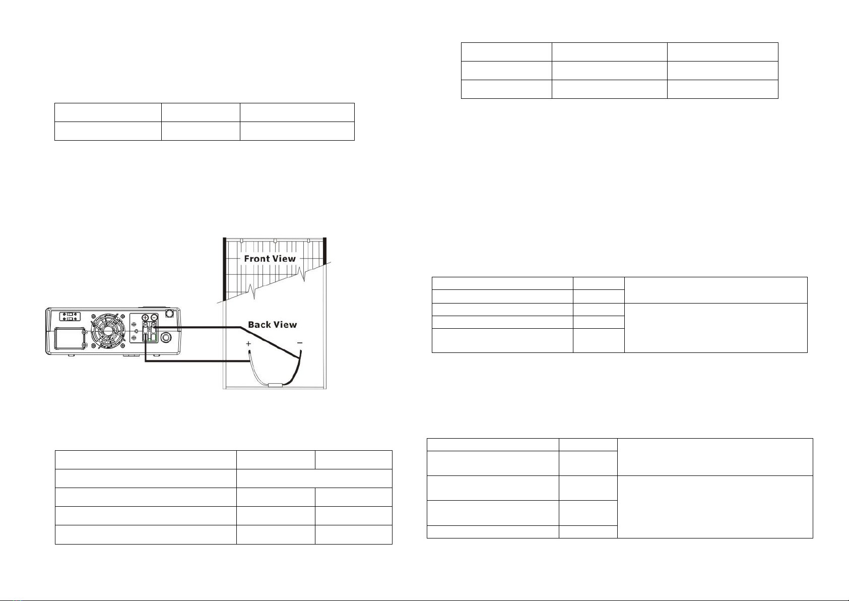
Step 1- Connect one cable to the positive (+) pole of solar panel and solar charger positive
(+) terminal.
Step 2- Connect the other cable to the negative (-) pole of solar panel and solar charger
negative (-) terminal.
Step 3- Check the solar charging indicator. If the LED lights up, it means that batteries are
charged by solar power. When the batteries are fully charged or there is no solar power
available, the LED will be off. (See following chart)
PV Module Selection:
When selecting proper PV modules, please be sure to consider below requirements
first:
1. Open circuit Voltage (Voc) of PV modules not exceeds max. PV array open circuit
voltage of inverter.
INVERTER MODEL
1.2KVA
2.4KVA
Charging Current (PWM)
30Amp
System DC Voltage
12Vdc
24Vdc
Operating Voltage Range
15~18Vdc
30~32Vdc
Max. PV Array Open Circuit Voltage
40Vdc
60Vdc
2. Max. Power Voltage (Vmpp) of PV modules should be close to best Vmp of
inverter or within Vmp range to get best performance. If one PV module cannot
meet this requirement, it’s necessary to have several PV modules in series
connection. Refer to below table.
Model
Best Vmp
Vmp range
1.2KVA
15Vdc
15V~18V
2.4KVA
30Vdc
30V~32V
Note: * Vmp: panel max power point voltage.
The PV charging efficiency is maximized while PV system voltage is close to
Best Vmp.
Maximum PV module numbers in Series: Vmpp of PV module * X pcs ≒
Best Vmp of Inverter or Vmp range
PV module numbers in Parallel: Max. charging current of inverter / Impp
Total PV module numbers = maximum PV module numbers in series *
PV module numbers in parallel
Take 1.2KVA inverter as an example to select proper PV modules. After considering
Voc of PV module not exceeds 45Vdc and max. Vmpp of PV module close to 15Vdc or
within 15Vdc ~ 18Vdc, we can choose PV module with below specification.
Maximum Power (Pmax)
85W
Max. PV module numbers in series
1 17.6 x 1 ≒15 ~ 18
Max. Power Voltage Vmpp(V)
17.6V
Max. Power Current Impp(A)
4.83A
PV module numbers in parallel
10 50 A / 4.83
Total PV module numbers
1 x 10 = 10
Open Circuit Voltage Voc(V)
21.6V
Short Circuit Current Isc(A)
5.03A
Maximum PV module numbers in Series: 1
PV module numbers in Parallel: 10
Total PV module numbers: 1 x 10 = 10
Take 2.4KVA inverter as an example to select proper PV module. After considering
Voc of PV module not exceed 60Vdc and max. Vmpp of PV module close to 30Vdc or
within 30Vdc ~ 32Vdc, we can choose PV module with below specification.
Maximum Power (Pmax)
260W
Max. PV module numbers in series
1 30.9 x 1 ≒30 ~ 32
Max. Power Voltage
Vmpp(V)
30.9V
Max. Power Current
Impp(A)
8.42A
PV module numbers in parallel
6 50 A / 8.42
Total PV module numbers
1 x 6 = 6
Open Circuit Voltage
Voc(V)
37.7V
Short Circuit Current Isc(A)
8.89A
Maximum PV module numbers in Series: 1
PV module numbers in Parallel: 6
Total PV module numbers: 1 x 6 = 6

6. Operation
Power On/Off
Once the inverter has been properly installed, press the power switch to turn on the unit. The
unit will work automatically in line mode or inverter mode according to input utility power's
status. When press the power switch again, the unit will be turned off.
LED Indicators & Audible Alarms
There are three indicators (Green/Red/Yellow) in the front panel of the unit.
Status
Indicator
Alarm
Line
mode
Battery charging at
power on.
Green LED flashing every
2 sec.
Off
Battery fully charged
at power on.
Green LED lighting
Off
Battery charging at
power off.
Green LED flashing every
5 sec.
Off
Battery fully charged
at power off.
Green LED flashing every
11 sec.
Off
Battery
mode
Battery weak
Yellow LED flashing every
2 sec.
Sounding every 1 sec.
None weak-battery
Yellow LED lighting
Off
Shutdown mode
Yellow LED flashing every
5 sec.
Off
Fault mode.
Red LED lighting
Continuously sounding for
30 min. and then alarm
off.
The unit is overload.
Red LED flashing for 0.5
sec every sec.
Sounding every 0.5 sec.
The unit is over charged.
Red LED flashing every 4
sec.
Continuously sounding for
30 min. and then alarm
off.
LCD Display & Audible Alarm
Status
LCD Display
Alarm
Line
mode
Battery charging at
power on.
and
flashing every 2 sec.
Off
Battery fully charged
at power on.
and
lighting.
Off
Battery charging at
power off.
and
flashing every 5 sec.
Off
Battery fully charged
at power off.
and
Off
flashing every 11 sec.
Battery
mode
Battery weak
and
will flash every 2
second.
Sounding every 1 sec.
None weak-battery
Off
Fault mode
Fault code will be
displayed.
Short fault: F0
Overload fault: F1
Battery bad: F2
High output voltage: F3
Main Relay Stick:F4
Fan fault: F5
Continuously sounding for
30 min. and then alarm
off.
The unit is overload.
The mark will
flash every second.
Sounding every 0.5 sec.
Load level indicator: Battery capacity indicator:
Display
Load Level
Display
Battery Capacity
75%~100%
battery voltage ≥ 12.5V (25V)
50%~75%
12.5V (25V)> battery voltage ≥
11.5V (23V)
25%~50%
11.5V (23V)> battery voltage ≥
11.0V (22V)
0%~25%
battery voltage < 11.0V (22V)
Operation Mode Selector
a). “UPS”: setting for conventional electrical appliance.
If you select this mode, the unit's input utility range will be 170~280VAC as normal home UPS.
If the utility is higher or lower than this range, the unit will transfer to inverter mode
automatically. And you can connect the computer systems or other precision home
equipment when you select this operation mode.
b). “INV.”: setting for energy saving
If you select this mode, the unit's input utility range will be extended to 90~280VAC. If the
utility is higher or lower than this range, the unit will transfer to inverter mode automatically.
So, you can connect the home equipments, such as light bulb, fluorescent tube, fan, or TV
on this mode.
Caution!! If you select the “INV.” mode and connect the computer to the output of the unit,
the computer may reboot if the input voltage is too low to be accepted.

7. Trouble Shooting
Use the table below to solve minor problems.
Problem
LCD/LED/
Buzzer
Possible Cause
Solutions
Utility power is
normal but
the unit is in
battery mode.
Input voltage
is displayed as
0 on the LCD
and yellow LED
is on or
flashing.
AC input power cord
is not connected
well.
Check AC input power
connection.
Input breaker is
activated.
Reset the input breaker.
When power
fails, the
backup time is
shorten.
Battery low
alarm issue
quickly
Battery voltage is
too low.
Charge the unit at least 8
hours.
Battery capacity is
not full even after
charge the unit for
at least 8 hours.
Check the date code of the
battery. If the batteries are too
old, replace the batteries.
When utility
power is
normal.
No LED display
on the front
panel
Battery is not
connected well.
Check the external battery
cable and terminal. Make sure
all the battery connections to
the unit are all correct.
Battery defect.
Replace the batteries.
Buzzer beeps
continuously
and red LED is
on.
LCD display F0
Output short
circuited.
Check if wiring is connected
well and remove abnormal
load.
LCD display F1
Overload error. The
inverter is loaded
with more than
110% load and time
is up
Reduce the connected load by
switching off some equipment.
LCD display F2
The battery voltage
is too low
(<1.4V/Cell)
1. Re-charge battery.
2. Replace battery.
LCD display F3
Output high
(Inverter voltage is
higher than 253Vac)
Return to repair center
LCD display F4
The relay had been
damaged during the
AC short circuit
Return to repair center.
LCD display F5
Fan fault
Replace the fan
If there is any abnormal situations occur, which doesn't list above, please call the service
people immediately for professional examine.
This manual suits for next models
1
Table of contents
Other PROLiNK Inverter manuals