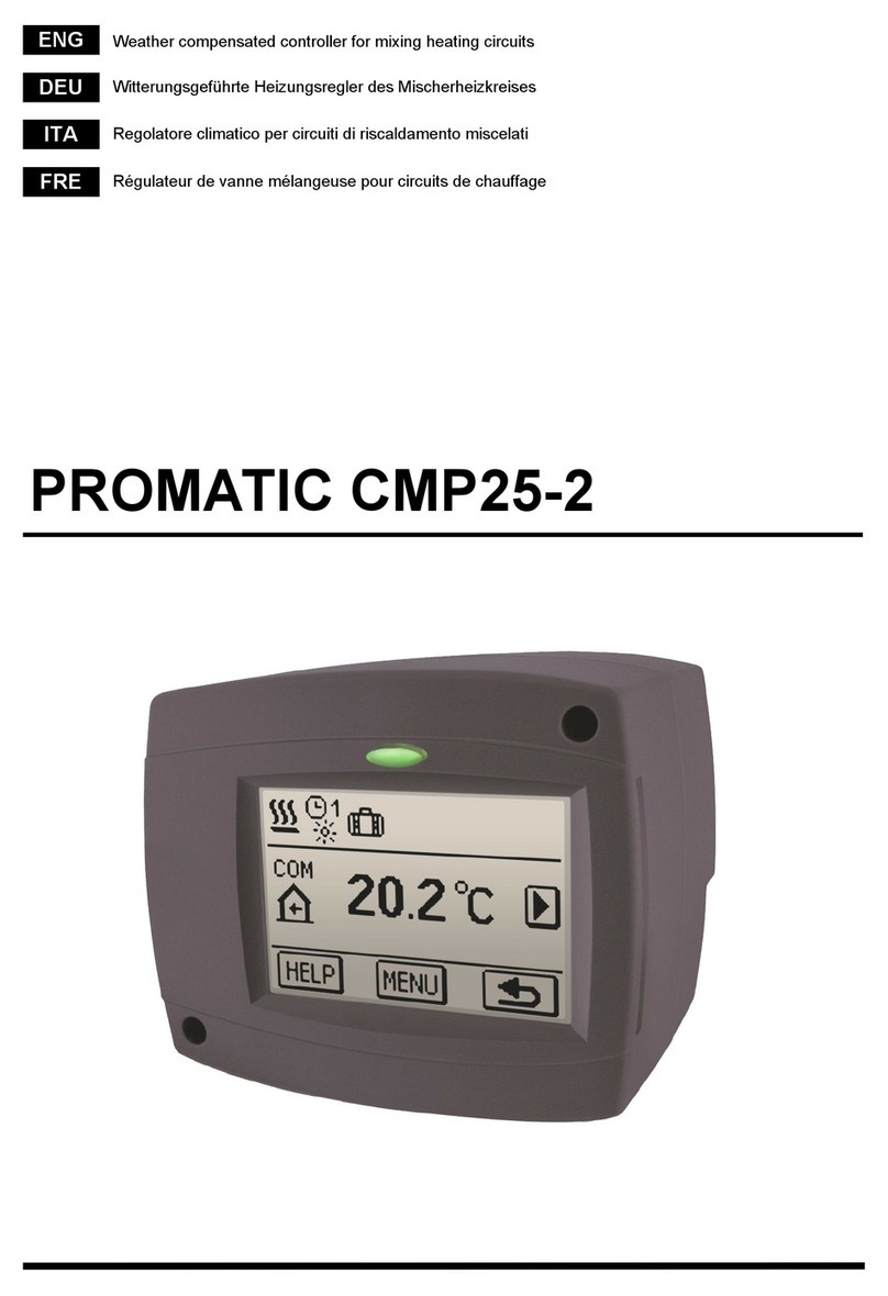
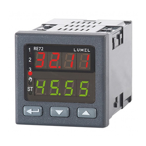
Promatic WDC10B User manual

PROMATIC WDC10B
- mixing or direct heating circuit controller
- d. h. w. warming controller
- liquid fuel boiler controller
PROMATIC WDC
Witterungsgeführte Heizungsregler
DEU
Weather compensated heating controller
ENG
PROMATIC WDC10
- mixing and direct heating circuit controller
- d. h. w. warming controller
- controller of systems with liquid or
solid fuel boiler
PROMATIC WDC20
- controller of two mixing circuit or direct and
mixing circuit
- controller of d. h. w. warming with boiler and
solar collectors
- liquid fuel boiler controller
- controller of systems with liquid or solid fuel
boiler, heat pump or bivalent systems
PROMATIC WDC10B
- Regler des Mischer- oder
Direktheizkreises
- Regler der Brauchwassererwärmung
- Kesselregler für Flüssigbrennstoff
PROMATIC WDC10
- Regler des Mischer- und Direktheizkreises
- Regler der Brauchwassererwärmung
- Regler von Kesselsystemen für
Flüssig- oder Festbrennstoff
PROMATIC WDC20
- Regler zweier Mischerheizkreise oder des
Mischer- und Direktheizkreises
- Regler der Brauchwassererwärmung mittels
Kessel und Sonnenkollektoren
- Kesselregler für Flüssigbrennstoff
- Regler eines Zweikesselsystems,
Wärmepumpe oder eines bivalentes
Systems


3
ENG DEU
Weather compensated heating controller
WDC10B, WDC10 and WDC20
Witterungsgeführte Heizungsregler
WDC10B, WDC10 und WDC20


User manual 5
ENG
INTRODUCTION
Weather compensated controllers WDC are intended for control of direct and/or mixing heat-
ing circuit or two mixing heating circuits and d. h. w. warming with a boiler, solar collectors
and other energy sources.
Weather compensated heating controller
WDC10B, WDC10 and WDC20
For initial setup see Initial controller setup, page 9!

User manual 6
ENG
CONTENTS
Introduction ................................................................................................................................ 5
USER MANUAL
Controller description ................................................................................................................. 8
Initial controller setup ................................................................................................................. 9
Graphic LCD display .................................................................................................................. 12
Description of symbols presented on the display ....................................................................... 13
Help screens, messages and warnings ...................................................................................... 17
Entering and navigating through the menu ................................................................................ 18
Menu structure and description of the menu .............................................................................. 18
Temperature settings ................................................................................................................. 23
User functions ............................................................................................................................ 24
Operating mode selection .......................................................................................................... 26
Setting time programs ................................................................................................................ 28
Basic settings ............................................................................................................................. 30
Data overview ............................................................................................................................ 32
SERVICE SETTING MANUAL
Controller parameters ............................................................................................................... 33
User parameters ........................................................................................................................ 33
Heating curve ................................................................................................................... 36
Service parameters ................................................................................................................... 38
Parameters for floor screed drying ............................................................................................. 50
Factory settings ......................................................................................................................... 51
Basic description of controller operation .................................................................................... 52
Mixing heating circuit ........................................................................................................ 52
Direct heating circuit ......................................................................................................... 53
Liquid fuel boiler ................................................................................................................ 54
Heat pump ........................................................................................................................ 54
Pump for additional mixing in boiler (bypass pump) .......................................................... 55
Domestic hot water ........................................................................................................... 55
Domestic hot water circulation .......................................................................................... 57
Remote heating activation ................................................................................................. 57
Operation of heating systems with two heat sources ........................................................ 57
Connection of temperature sensors .................................................................................. 59
Room unit DD2+ and RCD ................................................................................................ 60
Operation mode by sensor malfunction ............................................................................. 61
Expanding the system on multiple heating circuits ............................................................ 62
Connecting the controller to PC - SELCONTROL ............................................................. 63
Installation and connection of VT safety limiter ................................................................. 64
Divert valve operation by system with two heat sources ................................................... 65
Setting the minimum rotation rate of R6 pump .................................................................. 66
Sensor simulation. ............................................................................................................ 66
Differential controller ......................................................................................................... 67

User manual 7
ENG
INSTALLATION MANUAL
Controller installation .................................................................................................................. 68
Installation onto a wall ................................................................................................................ 69
Marking and description of temperature sensors ........................................................................ 69
Electrical connection of a controller ............................................................................................ 70
Connecting cables and sensors .................................................................................................. 71
Controller malfunction and servicing ........................................................................................... 72
Technical data ............................................................................................................................ 73
Disposal of old electrical and electronic equipment .................................................................... 75
Hydraulic schemes ..................................................................................................................... 145

User manual 8
ENG
USER MANUAL
CONTROLLER DESCRIPTION
1
2
3
4
5
6
8
7
2
1
3
Graphic display.
button (Esc - return to previous).
button (Help).
5
4
6
button(one step back, decrease).
7
8
Screw for fastening the cover.
button (enters a menu, confirms selection).
button (one step forward, increase).
Cover of the connection area.

User manual 9
ENG
INITIAL CONTROLLER SETUP
WDC heating controllers are equipped with an innovative solution which enables the setup of
controller in just three or four easy steps.
When the controller is connected to the network for the first time, the display first shows the
program version and company logo and then the first step of the procedure for controller
settings is presented.
Use buttons and to select the desired language.
Confirm the selected language by pressing .
The controller requires a confirmation of language selec-
tion with the button.
In case you chose the wrong language, return to the lan-
guage selection with the button.
If you do not find the desired language in the first screen, move to the next screen
with .
STEP 1 - SET LANGUAGE

User manual 10
ENG
Later you can change the selected hydraulic scheme with service parameter S1.1.
Select a hydraulic scheme for controller operation.
Move between schemes with buttons and .
Confirm the selected scheme by pressing .
STEP 2 - SET HYDRAULIC SHEME
The controller requires a confirmation of language selec-
tion with the button.
In case you choose the wrong scheme, return to scheme
selection with the button.
3. STEP- SET THE HEATING CURVE STEEPNESS FOR THE FIRST CIRCUIT
Set the heating curve steepness for room heating for the
first heating circuit.
Change the value with buttons and .
Confirm the selected value by pressing .
The controller requires a confirmation of the set heating
curve steepness with the button.
In case you choose the wrong heating curve steepness,
return to heating curve steepness selection with the
button.
Later you can change the heating curve steepness with parameter P2.1.
The meaning of heating curve steepness is described in detail on page 36.
All schemes with mixing heating circuit are
available for radiators and floor/wall heating.

User manual 11
ENG
Later you can alter the set heating curve steepness with parameter P3.1.
4. STEP - SET THE HEATING CURVE STEEPNESS FOR THE SECOND CIRCUIT1
Set the heating curve steepness for room heating for the
second heating circuit.
Change the value with buttons and .
Confirm the selected value by pressing .
1 This setting is not available in schemes with only one heating circuit.
The first and the second heating circuits are marked with their according num-
bers on hydraulic schemes.
RESET
Disconnect the controller from power supply. Press and hold the button and
connect power supply.
Attention! The controller will be reset and requires additional setting. When
the controller is reset, all of its previous settings are deleted.
The controller requires a confirmation of the heating curve
steepness setting with the button.
In case you choose the wrong scheme, return to heating
curve steepness selection with the button.

User manual 12
ENG
DESCRIPTION AND PRESENTATION OF THE BASIC SCREEN:
Review of data on the screen:
Operation mode and user functions appear separately for each circuit on the upper third of the
screen. To switch between heating circuits and the screen with the hydraulic scheme review
use the button.
Temperatures, active outputs, protection functions and other data appear in the middle section
of the screen. To review temperatures and other data, use buttons and .
The number of sensors and other data displayed on the screen depends on the selected hy-
draulic scheme and controller settings.
If you wish to retrieve the desired data after using the keyboard, look for the
data with buttons and , then confirm it by pressing the button
for 2 seconds.
Heating circuit.
Operation mode.
User functions.
Review of
temperatures,
protection
functions and
other data.
Time and
date.
Status of the controller's control outputs.
Messages
and war-
nings.
Review of
measured
temperatu-
res.
GRAPHIC LCD DISPLAY
On the LCD display we can look up all the important data for the controller operation.
Room unit.
If you press the button for 2 seconds, the temperature review will change
from a single line review into a double line review or vice versa. In the two-line
temperature review, the measured temperature appears in the first line, and the
desired or the calculated temperature appears in the second line.

User manual 13
ENG
DESCRIPTION OF SYMBOLS PRESENTED ON THE DISPLAY
SYMBOLS FOR OPERATION MODE INDICATION
Symbol Description
Room heating.
Room cooling.
Operation according to program interval - day temperature. *
Operation according to program interval - night temperature. *
Desired day temperature operating mode.
Desired night temperature operating mode.
D. h. w. warming according to program interval - switch-on interval. *
D. h. w. warming according to program interval - switch-off interval. *
Switch off.
Permanent switch-on of d. h. w. warming.
Manual operation mode.
Chimney sweep - emission measurement.
Symbol Description
The first - mixing heating circuit.
The second - direct or mixing heating circuit.
D. h. w. warming.
SYMBOLS FOR HEATING CIRCUITS
SYMBOLS FOR USER FUNCTIONS
Symbol Description
»PARTY« mode activated.
»ECO« mode activated.
Holiday mode activated.
One-time d. h. w. warming activated.
Anti legionella protection activated.
* The number inicates the first or the second time program accordingly.

User manual 14
ENG
SYMBOLS FOR INDICATION OF TEMPERATURES AND OTHER DATA
Symbol Description
Measured temperature.
Calculated or desired temperature.
Room temperature.*
Outdoor temperature.
Liquid fuel boiler temperature.
Solid fuel boiler temperature.
Gas boiler temperature.
Temperature of heat source obtained through BUS connection.
Combined fuel (liquid and solid) boiler temperature.
Heat source temperature - sensor in the pipeline.
Stand-pipe temperature.*
Return-pipe temperature.*
Domestic hot water temperature.
Heat accumulator temperature.
Solar collectors temperature.
Floor screed temperature. *
Boiler return-pipe temperature.
Exhaust gas temperature.
Temperature of the area where heat pump is installed.
Liquid fuel boiler switch-off.
Solid fuel boiler switch-on.
Automatic switch over to summer heating mode.
Floor screed drying activated.
Operation with constant temperature of stand-pipe activated.
Remote switch-on.
Boost heating activated.
- drying day
- duration of drying
* The number by the symbol or inside the symbol marks the first or the second time program accordingly.

User manual 15
ENG
D. h. w. circulation pipe temperature.
Solar collectors temperature - differential thermostat function.
Solid fuel boiler temperature - differential thermostat function.
Heat accumulator function - differential thermostat function.
D. h. w. storage tank temperature - differential thermostat function.
Bypass pump - differential thermostat function.
Burner.
Burner - second stage.
Bypass pump of the heating circuit (flashing indicates the pump must be
turned off).
R12345678
R12345678 Status of the controller's control outputs - relays are switched on.
Status of the controller's control outputs - relays are switched off.
Mixing valve - closing (flashing indicates it must be closed).
Mixing valve - opening (flashing indicates it must be opened).
Change-over valve - closing.
Change-over valve - opening.
Bypass pump for d.h.w.
Circulation pump for d.h.w.
Solar collectors bypass pump.
Boiler bypass pump.
Boiler leading pump.
Heat pump.
Electric heater.
Electric heater for d.h.w.
Output operation according to time program.
T1, T2, T3, ... T8
TR1, TR2
TA
TQ
Temperature measured by sensors T1, T2, T3, T4, T5, T6, T7 or T8.
Temperature measured by a room sensor or room unit DD2+.
Outdoor temperature, obtained through the BUS connection.
Heat source temperature, obtained through the BUS connection.

User manual 16
ENG
SYMBOLS FOR THE INDICATION OF COMMUNICATION BETWEEN DEVICES
CONNECTED
Symbol Description
Devices connected to communication port COM1.
Room unit is connected. The number beside room unit indicates, whether
this is the first or the second room unit.
Single controller - not in BUS network.
The first (master) controller in BUS network.
The last (slave) controller in BUS network.
Controller and communication port COM1/COM2 status.
Intermediate (slave) controller in BUS network.
SYMBOLS FOR PROTECTION FUNCTIONS
Symbol Description
Liquid fuel boiler overheating protection.
Solid fuel boiler overheating protection.
Solar collectors overheating protection.
Accumulator overheating protection.
D. h. w. storage tank overheating protection.
D. h. w. storage tank overheating protection - cooling directed into the boiler.
D. h. w. storage tank overheating protection - cooling directed into the
collectors.
Protection again room freezing.
Frost protection - boliler switch-on to minimum temperature.

User manual 17
ENG
SYMBOLS FOR MESSAGES AND WARNINGS
Symbol Description
Message
In the event of exceeding the maximum temperature or when a protec-
tion function is switched on, the controller will cause an appropriate
symbol on the display to flash. When maximum temperature is no longer
exceeded or when a protection function has switched off, a turned on
symbol will note the recent event. By pressing the button, the messa-
ge review screen is retreived.
Warning
In the event of sensor malfunction, BUS network error or COM connec-
tion error, the controller will cause an appropriate symbol on the display
to flash. When the error is remedied or is no longer present, a turned on
symbol will note the recent event. By pressing the button, the messa-
ge review screen is retreived.
Messages deletion
By pressing the button deletion of all unconnected sensors is executed.
Attention: You will not be able to delete the sensors necessary for the con-
troller's operation.
By pressing the button, the help, messages and warnings screen is retreived. A new
window opens in which the following icons are available
Short instructions
Short instructions on the use of controller.
Controller version
Review of the controller type and program version.
Messages
List of exceeded maximum temperatures and list of protection functions activati-
ons. By pressing the buttons and navigate through the list of mes-
sages. Exit the list by pressing the button.
Warnings
List of sensors and other compounds malfunctions.
By pressing the buttons and navigate through the list of messages.
Exit the list by pressing the button.
HELP, MESSAGES AND WARNINGS SCREEN

User manual 18
ENG
ENTERING AND NAVIGATING THROUG THE MENU
To enter the menu press the button.
To navigate through the menu, use buttons and , and confirm your selection by
pressing the button.
You can return to the previous screen by pressing .
If no button is pressed for some time, the screen lightning will be switched off or
reduced according to the setting.
MENU STRUCTURE AND DESCRIPTION
TEMPERATURES SETTING
Day temperature for circuit 1
Night temperature for circuit 1
Day temperature for circuit 2 *
Night temperature for circuit 2 *
D. h. w. temperature
USER FUNCTIONS
USER FUNCTIONS FOR THE FIRST HEATING CIRCUIT
PARTY operation mode.
* The setting is only available in schemes with two heating circuits.

User manual 19
ENG
* The setting is only available in schemes with two heating circuits.
** The setting is only available in schemes with change-over of heat sources.
ECO operation mode.
Holiday operation mode.
Function switch-off.
USER FUNCTIONS FOR THE SECOND HEATING CIRCUIT *
PARTY operation mode.
ECO operation mode.
Holiday operation mode.
Function switch-off.
USER FUNCTIONS FOR D.H.W.
One-time switch-on of d.h.w.warming.
Function switch-off.
USER FUNCTIONS FOR ENERGY SOURCES **
One-time switch-on of liquid fuel boiler.
Switch-off of liquid fuel boiler.
Start-up of solid fuel boiler.
Function switch-off.
OPERATION MODE SELECTION
Operation mode according to selected time program.
Operation mode according to day temperature.
Operation mode according to night temperature.
OPERATION MODE FOR THE FIRST HEATING CIRCUIT
Switch-off.

User manual 20
ENG
OPERATION MODE FOR THE SECOND HEATING CIRCUIT*
Operation mode according to selected time program.
Operation mode according to day temperature.
Operation mode according to night temperature.
Switch-off.
OPERATION MODE FOR D. H. W. WARMING
D. h. w. warming according to selected time program.
Permanent switch-on of d. h. w. warming.
Switch-off.
SELECTION OF OPERATION MODE HEATING OR COOLING
TIME PROGRAMS
TIME PROGRAM FOR THE FIRST HEATING CIRCUIT
The first time program.
The second time program.
TIME PROGRAM FOR THE SECOND HEATING CIRCUIT*
The first time program.
The second time program.
TIME PROGRAM FOR D. H. W.
The first time program.
The second time program.
MANUAL OPERATION OF OUTPUTS
CHIMNEY SWEEP
* The setting is only available in schemes with two heating circuits.
This manual suits for next models
3
Table of contents
Languages:
Other Promatic Controllers manuals
Popular Controllers manuals by other brands
Zeagle
Zeagle F8 OCTOPUS owner's manual
ZPA Pecky, a.s.
ZPA Pecky, a.s. MODACT MOK 125 Installation and operating instructions
MultiScan
MultiScan TD-32 series operating manual
GEZE
GEZE ST220 user manual
Ametek
Ametek ZF1 SSR Series Instruction, Operation and Maintenance Manual

Elstat
Elstat Nexo CMS200 product manual
