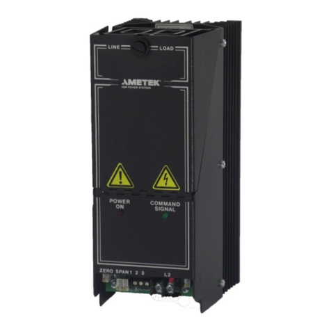
ZF1 SCR Power Controller Table of Contents
Rev 3 Ametek HDR Power Systems i
TABLE OF CONTENTS
IMPORTANT SAFETY INSTRUCTIONS ............................................................................................................. 1
CHAPTER 1 - DESCRIPTION .............................................................................................................................. 3
1.1 General Description 3
1.2 Application 3
1.3 Specification 3
1.4 Option NO/NC (Thermostat) 3
1.5 Option FK (Fuse Kit) 3
1.6 Option TX (24 Vac Transformer) 3
CHAPTER 2 - INSTALLATION ............................................................................................................................ 5
2.1 Mounting the ZF1 5
2.2 Load Wiring 5
2.3 Line Wiring 5
2.4 Wiring Input Fuse 6
2.5 Command Signal Input 6
2.6 Heatsink Thermostat Contacts 6
CHAPTER 3 - OPERATION ................................................................................................................................. 7
3.1 General 7
3.2 Command Signal Indicator 7
3.3 Command Input Control 7
CHAPTER 4 – TROUBLESHOOTING ................................................................................................................. 9
4.1 Customer-Service Program 9
4.2 Troubleshooting Typical Symptoms 9
4.3 Static Precautions when Servicing 9
4.4 Environmental Problems 10
4.5 Input Power and Load Connections 10
4.6 Correcting Troubles in the ZF1 Itself 11
CHAPTER 5 - SERVICE ..................................................................................................................................... 13
5.1 Communication Procedures 13
5.2 Spare Parts Orders – Routine or Emergency 13
5.3 Spare Parts List 14
5.4 Drawing List 14
CHAPTER 6 – WARRANTY POLICY ................................................................................................................ 15
6.1 Warranty 15
6.2 In-house Repair Services 15
APPENDIX .......................................................................................................................................................... 17
Appendix A – System Schematic (-C models only) 17
Appendix B – System Schematic 18
Appendix C – 15-40 A Outline 19
Appendix D – 70 A Outline 20
Appendix E – Option TX Transformer Outline 21
Appendix F – Option FK Mounting 21
Appendix G – Declaration of Conformity 22
