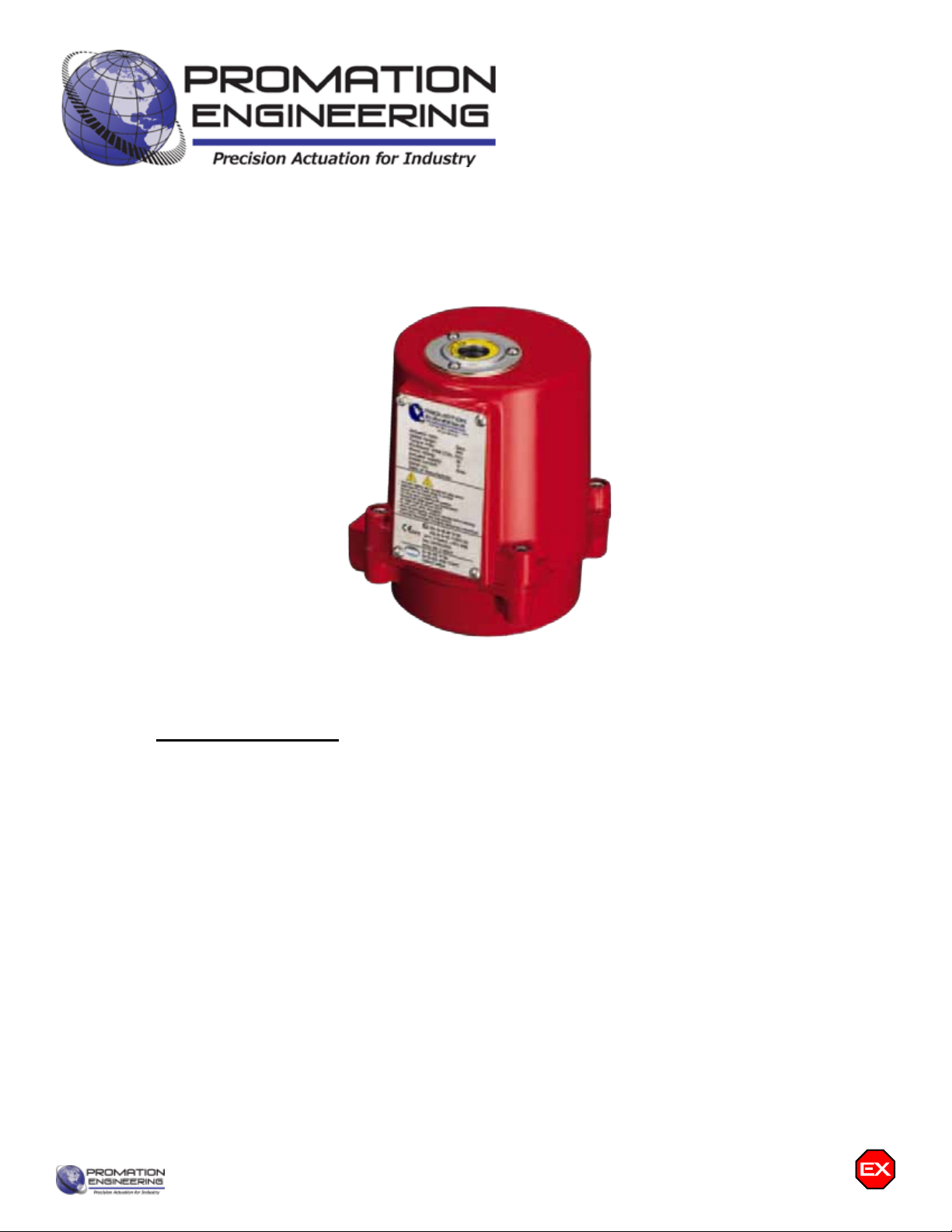
Promation Engineering PX1 Series User manual

Installation & Operation
Manual
This IOM is for the following
ProMation Engineering Products:
PX1-24N7+ACDC
PX1-24N7+DC
Division System
CAN/CSA-C22.2 No. 0-10, CSA C22.2 No. 30-M1986, CSA C22.2 No. 25-17, FM
3600, FM 3615, FM 3616
Class I Division 1 Groups C,D T4
Ambient Temperature - 30 °C to + 70 °C ( - 22 °F to + 158 °F )
Class II Division 1 Groups E,F,G T130°C
Ambient Temperature - 30 °C to + 70 °C ( - 22 °F to + 158 °F )
Zone System
CAN/CSA-C22.2 No. 0-10, CAN/CSA-C22.2 No. 60079-0, CAN/CSA-C22.2 No.
60079-1,
CAN/CSA-C22.2 No. 60079-31, UL 60079-0, UL 60079-1, UL 60079-31
Class I, Zone 1, AEx db IIB Gb T4
Class II Zone 21, AEx tb IIIC T130°C

This page intentionally left blank
Contents
2 . . . . . . . . . . . . . . . . . . . Product Specifications
3 . . . . . . . . . . . . . . . . . . . Shipping and Handling
3 . . . . . . . . . . . . . . . . . . . Product Mounting and Setup
3 . . . . . . . . . . . . . . . . . . . Installation Notes
4 . . . . . . . . . . . . . . . . . . . Wiring Diagram
4 . . . . . . . . . . . . . . . . . . . Torque Switches
5 . . . . . . . . . . . . . . . . . . . Layout of Controller
6 . . . . . . . . . . . . . . . . . . . Check End of Travel Settings
6 . . . . . . . . . . . . . . . . . . . Status Indicators
7 . . . . . . . . . . . . . . . . . . . Adjusting the actuator CW position
8 . . . . . . . . . . . . . . . . . . . Adjusting the actuator CCW position
9 . . . . . . . . . . . . . . . . . . . Adjusting the actuator Auxiliary Switches
10 . . . . . . . . . . . . . . . . . . Mechanical Data
11 . . . . . . . . . . . . . . . . . . Mechanical Data
12-14 . . . . . . . . . . . . . . . Commissioning
15 . . . . . . . . . . . . . . . . . . AutoCalibration Procedure
IOM Template Master.indd
Page 1 of 17 P2/3 Series HV-TS AdVanced Proportional Control
Table of Contents
2 ................... Product Specifications
3 ................... Hazardous Location Notes
5 ................... Shipping and Handling
5 ................... Product Mounting and Setup
5 ................... Installation Notes
6 ................... Wiring Diagram
7 ................... Check End of Travel Settings
7 ................... Adjusting the actuator CCW and CW positions
8 ................... Adjusting the actuator Auxiliary Switches
9 ................... Mechanical Dimensions
10 .................. Mechanical Data
11 .................. Commissioning
FM_PX1 LV N7 Ver B 072921
Page 1 of 11 P1 HV Series
Field Manual
PX1- Series LV
On/Off/Jog Control
ISO5211 F03/05 8P14

50°F
10°C
75°F
24°C
100°F
38°C
125°F
52°C
150°F
65°C
25%
50%
75%
100%
On/Off/Jog
Proportional
Ambient Temperature
Introduction
The following procedure is to be followed for set-up, calibration, testing and use of the P Series quarter-turn
electric actuators. Each unit is shipped from the factory with initial calibration of cams and switches completed for
0-90 degree operation. However, these are general settings and serve as a starting point for proper calibration
of the actuator in its real-world application. There are no mechanical stops on this model.
Safety
Safety is a basic factor any time you maintain and operate mechanical equipment. Use of proper handling
methods, tools and clothes can help prevent serious accidents -- accidents which can cause injuries to you
or a fellow worker. This manual was created to enable a trained user to install, adjust and troubleshoot your
ProMation P Series actuator.
Only competent and trained personnel should install, maintain and repair ProMation Actuators. Any work related
to this Actuator must be carried out in accordance with this manual and related codes and regulations. Local
workplace health and safety rules should always be followed.
Duty cycle
Duty cycle is the percent of time that an actuator spends running as a fraction of the total time. Duty Cycle is
directly related to heat; overusing an actuator typically results in motor overheating which can permanently
damage it. Overheating also consumes more electricity. Generally speaking, the hotter a motor becomes, the
longer‘rest’itneedstocooldownsoitrunsefficiently.
Actuator Speci cations P1
Torque “lb/Nm 300”lbs/35Nm
Supply Voltage 12vac/dc 24vac/dc
Max Inrush Current 2.0A 2.8/1.8A
Running Current 1.9A 1.6/1.4A
Motor DC Brush Type
Runtime (90°@60Hz/vdc) 15 sec
Runtime (90O@50Hz) 15 sec
Duty Cycle 75%
Motor Starts 1200 per hour
Weight 5lbs/3kg
Mechanical Connections ISO5211 F03/F05 8pt 14mm
Electrical Entry (2) 1/2” NPT
Electrical Terminations 14-18ga
Environmental Rating NEMA 4/4X
Manual Override 8mm Socket Drive
Control On/O/Jog
Actuator Case Material Aluminum Alloy, Powder coated
Motor Protection 230°F/110°C Thermal F* Class
*Totally Enclosed Non-Ventilated Motors
Ambient Temperature
Operating Range
-22°F to +125°F
-30°C to +52°C
Wire Sizing Chart
MAX distance between Actuator
and Supply (feet)
Actuator/
Voltage
P1
12VAC/DC
P1
24VAC/DC
2.0A 1.6A
18 41 103
16 65 162
14 105 262
Wire
Gage
Amps
P1 LV N4
FM_PX1 LV N7 Ver B 072921
Page 2 of 11 P1 HV Series
Product Specications
PX1
, 7, 9
-22°F to +158°F
-30°C to +70°C.

1 General Information
1.1 Safety Instructions
• Installation, maintenance and repair must be performed by trained personnel.
• The handling shall follow the safety and warning instructions contained in this manual.
• The user should read and follow instructions contained in this operation manual. Failure
to do this may result in damages and void warranty. ProMation Engineering is not liable
for damages due to operator negligence or misuse.
• All national, regional and local health and safety codes are to be followed when in
installing and operatring equipment.
• The surface temperature may exceed 60°C (140°F). Please check the surface
temperature before operation, using an appropriate thermometer and protective clothing
before operation.
1.2 Installation Notices
1.2.1 Hazardous Location Information
• DO NOT install in ambient temperatures that exceed 70 °C (158 °F).
• DO NOT, under any circumstances, remove the cover of the actuator while in a
hazardous location when the power is still live inside the actuator. This could cause
ignition of a hazardous atmosphere.
• DO NOT, under any circumstances, use an explosion-proof electric actuator in a
hazardouslocationthatdoesnotmeetthespecicationwhichtheactuatorwas
designed for.
• When removing the actuator, care must be taken not to scratch, scar or deform the
amepathofthecoverorbaseoftheactuator.Thatwillnegatetheprotectionratingof
the enclosure in a hazardous location.
• The explosion proof electric actuator is shipped with matched mating surfaces of the
cover and base. When assembling or dissassembly the cover from the actuator, match
the mating number (QA code) of the top with the bottom. to assure hazardous location
protection.
• Please read operation manual and wiring diagram carefully before installation.
• Verify that supply voltage is in accordance with the data on nameplate to prevent
electricl component damage caused by incorrect power input.
• Turnpowerobeforeperfominganyinstallation,wiringormaintenanceprocedures.
• There are grounding devices both inside and outside of the actuator. Ground wires
should be connected properly.
• Themetalplugsinconduitentriesarefortransitonly.Forlongtermprotectiont
suitableameproofcableglandandpowercableshouldbewithaminimumwithstand
temperature105 °C (221°F).
• Failure to follow safety instructions may cause serious injury, equipment damage, or
void warranty
• Mount, calibrate, and test actuators only during non-hazardous conditions.
• All electrical connections must be to national, state, and local codes and in
accordancewithhazardouslocationspecicationsforwhichthisactuatoristobe
used.
Hazardous Location Actuators
FM_PX1 LV N7 Ver B 072921
Page 3 of 11 P1 HV Series

Hazardous Location Information (Continued)
• Do not touch any components on the PCB with metal tools or bare hands to avoid functional
failure caused by static electricity discharge.
• Do not parallel wire multiple actuators together without using isolation relay(s).
• Use proper techniques when installing conduit and properly seal the connection. Do not
mount the actuator with conduit entries in such a position that allows condensation to enter
the unit.
• Actuator should be installed in an upright or horizontal position. Do not mount upside down or
below a horizontal position.
• Periodically inspect actuator enclosure to prevent water intrusion and dust accumulation.
• Checkthemarkingandcerticatenumbertoseeifitconformstotheindicatedapplication.
• All the parts of the housing are assembled in the right manner and fastened. USE
FASTENERSWITHYIELDSTRESS≥700MPa.
• KEEP COVER TIGHT WHILE CIRCUITS ARE ALIVE. AFTER DE-ENERGIZING, DELAY
10 MINUTES BEFORE OPENING THE COVER.
• SEAL REQUIRED WITHIN 18 INCHES (450 mm) OF ENCLOSURE (for Divisions only).
• SEAL REQUIRED WITHIN 2 INCHES (50 mm) OF ENCLOSURE (for Zones only).
• The actuator is delivered with two conduit entries plugged by metal plugs. Use cable glands
rated for the corresponding hazardous location designation. The electrical supply cable
must be suitable for power rating and with a temperature rating of greating than 105 °C
(221 °F).
CSA Testing
• Atmospheric pressure : 80 - 106 kPa.
• Ambient temperature: -30 °C to +70 °C (-22 °F to +158 °F).
• Air with normal oxygen content: 21 % (Volume).
FM_PX1 LV N7 Ver B 072921
Page 4 of 11 P1 HV Series
FM_PX1 LV N7 Ver B 072921
Page 5 of 11 P1 HV Series
Shipping and Handling
1. This actuator is shipped in the FULLY CW (position indicator shows “CLOSE”)
position.
2. THIS ACTUATOR MUST HAVE WATER TIGHT HAZARDOUD LOCATION EMT
FITTINGS WITH CONDUIT DRAINAGE INSTALLED AND POWER SUPPLIED
TO UNIT TO KEEP THE HEATER WARM AT THE TIME OF INSTALLATION.
3. Storage: This unit should NOT be stored outside unless it is powered up
and has proper conduit terminations. When NOT powered up, it should be
stored in a clean, dry environment at all times.
4. This actuator has been factory calibrated to operate between 0 degrees and
90 degrees. Most quarter-turn products will not require recalibration of
these settings. If any travel adjustment is necessary, please refer to pages 5
& 6 for instructions.
Product Mounting and Setup
1. Note: This design utilizes NO MECHANICAL stops. It is recommended that you do NOT use the manual override
until the actuator is mounted to a valve or damper that has 90 degree limited travel.
2. Fully CLOSE the valve or damper to which the actuator is to be mounted.
• Keep in mind this actuator rotates CW (as viewed from above the unit) when driving CLOSED.
3. Assemble necessary linkage components and attach the actuator to the driven device.
4. Tighten mounting bolts, making sure actuator is centered on the device drive shaft.
5. Utilize the manual override (8mm hex output drive on bottom of actuator) to check for unobstructed manual operation
from fully CW to fully CCW positions BEFORE applying power to the unit.
Warning: DO NOT operate manual override when power is present. Geartrain damage
and personal injury may occur.
Do not use powered tools to turn the manual override -- it will DAMAGE the gear train or
motor and VOID the warranty.
6. Make the electrical connections per wiring diagram on page 6.
• For operation only four connections are needed. The balance of the connections are used for options and features.
• Terminals A, B & C are an aux switch for the open position (adjustable).
• Terminals A, E & F are an aux switch for the closed position (adjustable).
• Both Switches above share a common terminal “A”. Terminals A-F on the switch card are for the (adjustable) aux
switches. They are dry type Form C rated 3A @ 250vac MAX.
7. Do NOT apply power at this time.
Installation Notes
• There are no mechanical stops on this model.
• These actuators are designed to be used in either a horizontal or upright position. Do NOT mount the assembly with
the actuator top below a horizontal position.
• When installing conduit, use proper techniques for entry into the actuator. Use drip loops to prevent conduit condensate
from entering the actuator.
• Both NPT conduit ports MUST use proper equipment to protect the NEMA 4X integrity of the housing.
• The internal heater is to be used in ALL applications.
• Do NOT install the actuator outdoors or in humid environments unless it is powered up and the heater is functioning.
• Use proper wire size to prevent actuator failure (see chart on page 4 for proper wire sizing).
• All terminals accept 14-18AWG solid/stranded wire.
• Do NOT parallel wire multiple actuators together without utilizing isolation relays! If this is your intention,
please contact ProMation Engineering for a multiple actuator parallel wiring diagram.
The actuator is shipped from the
factory in its fully CW position.
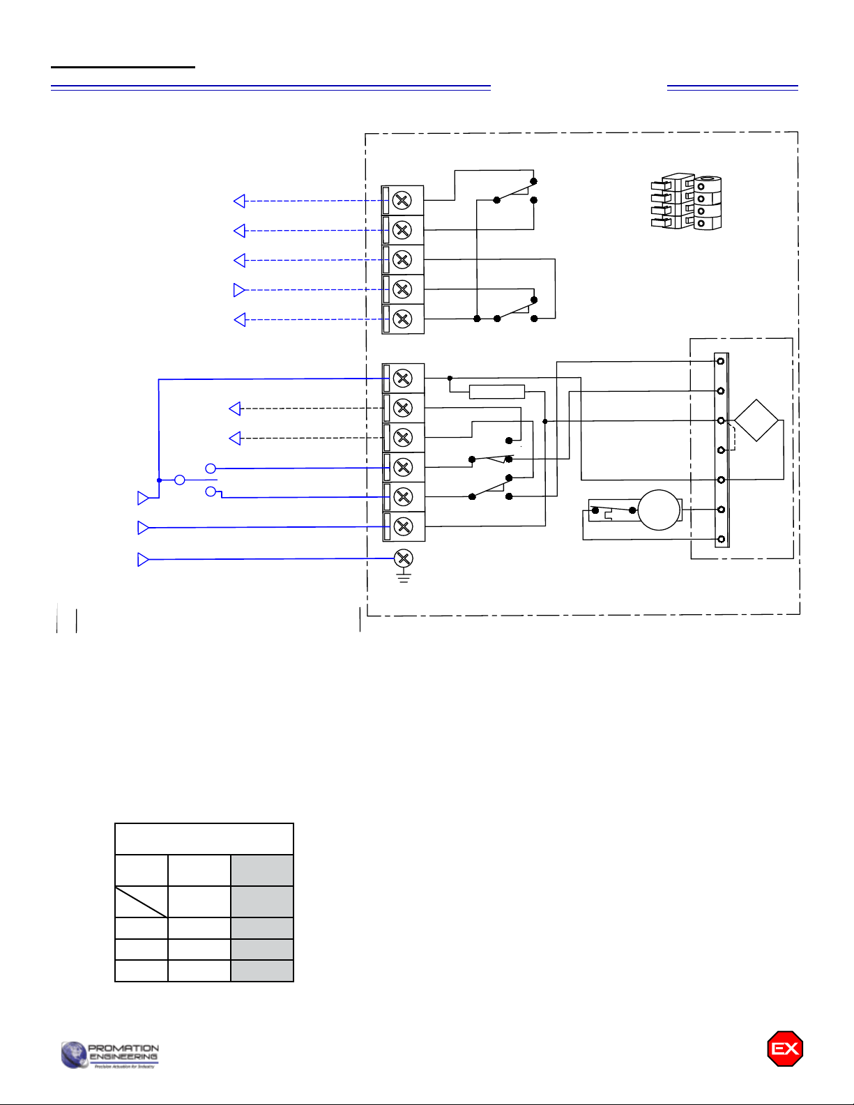
Actuator ships in fully closed position!
Items within dotted line located inside actuator housing
SW1
SW2
SW3
SW4
Switch Stack
Detail
NOT CLOSED*
CLOSED*
NOT OPEN*
AUX SW COM*
OPEN*
RUN CLOSED
CLOSED PILOT*
RUN OPEN
OPEN PILOT*
HOT/POS (+)
F
E
C
B
A
7
6
5
4
1
* CONNECTIONS
OPTIONAL
FIELD
CONTROL
DEVICE
HEATER
SW1
SW2
SW3
SW4
AUXILIARY
SWITCH
(STANDARD)
AUXILIARY
SWITCH
(STANDARD)
3
NEU/NEG (-)
open
close
open aux
close aux
THERMAL SWITCH
DC DRIVE
MOTOR
ALL SWITCHES
SHOWN WITH
ACTUATOR IN
FULL OPEN
POSITION
1
2
3
4
5
6
7
M
FIELD WIRING
(BY OTHERS)
INTERNAL WIRING
(FACTORY)
BLK
P1-24N4+ACDC
A
WD-850-1A101
OP
(-)
CL
OPP
CLP
(+)
408-30042
WHT
BLU
GRY
WHT
RED
Blue PCB
(POS switched)
24 VAC/VDC
HOT/POS
NEU/NEG
-
+
~~
On Board
GND Screw
GND
FM_PX1 LV N7 Ver B 072921
Page 6 of 11 P1 HV Series
On/O/Jog Control
Wiring Diagram
Wire sizing data is provided in the Wire Sizing Data table to assist in the selection
of the proper wire size for ProMation P1 series actuators using various wire
sizes over distance.
Please make sure to reference the correct voltage and do not exceed the
indicated length of the wire run for each model.
Actuator Speci cations P1
Torque “lb/Nm 300”lbs/35Nm
Supply Voltage 24vac 24vdc
Max Inrush Current 3.0A 1.6A
Running Current 2.8A 1.3A
Motor DC Brush Type
Runtime (90°@60Hz/vdc) 15 sec
Runtime (90O@50Hz) 15 sec
Duty Cycle 75% maximum
Motor Starts 1200 per hour
Weight 5lbs/3kg
Mechanical Connections ISO5211 F03/F05 8pt 14mm
Electrical Entry (2) 1/2” NPT
Electrical Terminations 14-18ga
Environmental Rating NEMA 4/4X
Manual Override 8mm Socket Drive
Control Proportional
Actuator Case Material Aluminum Alloy, Powder coated
Motor Protection 230°F/110°C Thermal F* Class
*Totally Enclosed Non-Ventilated Motors
Ambient Temperature
Operating Range
-22°F to +125°F
-30°C to +52°C
P1 LV PN4
MAX distance between
Actuator and Supply (feet)
Actuator/
Voltage
P1
24VAC
P1
24VDC
2.8A 1.3A
18 59 127
16 93 200
14 150 323
Wire
Gage
Amps
Wire Sizing Chart
Internal Actuator
Wiring
Field Wiring
Remove power from this device BEFORE making any End of Travel cam adjustments.
Cam 1 Adjustment
1. The lower cam is Cam 1, the CCW end-of-travel adjustment. Once the actuator
is at its required CCW position, with POWER OFF, use a 2.5mm hex key to
free up the cam set screw. Once it is free, rotate the hex key to the LEFT 10-15
degrees to reset the switch roller arm. Then snug the set screw up against the
camshaft (CW) until slight pressure is felt. Then SLOWLY rotate the hex key
pushing the cam to the RIGHT until you hear the “click” on the bottom switch
indicating that correct adjustment has been achieved. Tighten the cam.
2. Apply power to the actuator and drive CW at least 15-20 degrees. Then drive
the actuator CCW until the cam stops the electrical travel. Check to be sure this
is the correct CCW position you require. Repeat step 1 if further adjustment
is needed.
3. If using the Auxiliary Switches, adjust Cam 3 per instructions on page 6.
Cam 2 Adjustment
1. The second cam is Cam 2, the CW end of travel adjustment. Once the actuator
is at its required CW position with POWER OFF, use a 2.5mm hex key to free
up the cam set screw. Once it is free, rotate the hex key to the RIGHT 10-15
degrees to reset the switch roller arm. Then snug the set screw up against the
camshaft (CW) until slight pressure is felt. Then SLOWLY rotate the hex key to
the LEFT until you hear the “click” on the second switch indicating that correct
adjustment has been achieved. Tighten the cam set screw.
2. Apply power to the actuator and drive CCW at least 15-20 degrees. Then drive
the actuator CW until the cam stops the electrical travel. Check to be sure this
is the correct CW position you require. Repeat step 1 if further adjustment is
needed. Remove power from the actuator.
3. If using the Auxiliary Switches, adjust Cam 4 per instructions on page 6.
Cam 1
Cam 2
NC
NO
COM
LESS
CLOSED
CLOSED
LIMIT SWITCH
FURTHER
CLOSED
FURTHER
OPEN
OPEN
LIMIT SWITCH
LESS
OPEN
NC
NO
COM
NC
NO
COM
NC
NO
COM
LESS
CW
CW
LIMIT SWITCH
FURTHER
CW
FURTHER
CCW
CCW
LIMIT SWITCH
LESS
CCW
OLD
NEW
NC
NO
COM
LESS
CLOSED
CLOSED
LIMIT SWITCH
FURTHER
CLOSED
FURTHER
OPEN
OPEN
LIMIT SWITCH
LESS
OPEN
NC
NO
COM
NC
NO
COM
NC
NO
COM
LESS
CW
CW
LIMIT SWITCH
FURTHER
CW
FURTHER
CCW
CCW
LIMIT SWITCH
LESS
CCW
OLD
NEW
The actuators are tested, calibrated and shipped in the Full CW position and End of Travel cams are set at 90 degrees
from each other.
A. Set the control device (valve or damper) to the closed position.
B. Mount the actuator to the device to be controlled (valve or damper).
C. Insure that the CW End of Travel cam trips the CW End of Travel switch at the correct CW point.
C.1. If the switch does not change state at the correct CW position, adjust CAM 2 per instructions below.
D. Manually move (see Manual Override on page 6) the actuator so the valve or damper is in the fully CCW position.
E. Insure that the CCW End of Travel cam trips the CCW End of Travel switch at the correct CCW point.
E.1. If the switch does not change state at the correct CCW position, adjust CAM 1 per instructions below.
FM_PX1 LV N7 Ver B 072921
Page 7 of 11 P1 HV Series
Check End of Travel Settings
Adjusting the actuator CCW and CW positions (Cam adjustment)

Remove power from this device BEFORE making any End of Travel cam adjustments.
Cam 3 Adjustment
1. The third cam is Cam 3, the CCW auxiliary switch adjustment. Drive the
actuator to its CCW position. Then use a 2.5mm hex key to free up the cam
set screw. Once it is free, rotate the hex key to the LEFT 10-15 degrees to
reset the switch roller arm. Then snug the set screw up against the camshaft
(CW) until slight pressure is felt. Then SLOWLY rotate the hex key and cam
to the RIGHT until you hear the “click” on the third switch. Continue to rotate
the cam between 3 and 5 degrees to the RIGHT to make sure the auxiliary
cam switch changes state before the actuator reaches its end of travel
electrically. Tighten the cam set screw.
Cam 4 Adjustment
1. The fourth cam is Cam 4, the CW auxiliary switch adjustment. Drive the
actuator to its CW position. Then use a 2.5mm hex key to free up the cam
set screw. Once it is free, rotate the hex key to the RIGHT 10-15 degrees to
reset the switch roller arm. Then snug the set screw up against the camshaft
(CW) until slight pressure is felt. Then SLOWLY rotate the hex key to the
LEFT until you hear the “click” on the fourth switch. Continue to rotate the
cam between 3 and 5 degrees to the LEFT to make sure the auxiliary
cam switch changes state before the actuator reaches its end of travel
electrically. Tighten the cam set screw.
Cam 3
Cam 4
Warning: DO NOT operate manual
override when power is present. Geartrain
damage and personal injury may occur.
Do not use powered tools to turn the
manual override -- it will DAMAGE the gear
train or motor and VOID the warranty.
Manual Override
FM_PX1 LV N7 Ver B 072921
Page 8 of 11 P1 HV Series
Adjusting the actuator Auxiliary Switches

FM_PX1 LV N7 Ver B 072921
Page 9 of 11 P1 HV Series
Drawn By
Finish
Promation Engineering Inc.
16138 Flight Path Drive
Brooksville, Fl 34604
Phone: 352-544-8436
Fax: 352-544-8439
This Document is the property of ProMation Engineering,
Inc. Distribution of this document without the written
consent of the owner is Strictly forbidden.
Failure to comply will incur a liability for Damages.
Checked By
1/7/2020
Rev.
A
NO SCALE Sheet Number: 1
Material
ProMation Engineering, Inc.
DJG
PMR
1/6/2020
PX1 F0305 8P14 DimData.idw
Created:
Last Checked:
Part No.
Dwg. Name
Dimensional Data for PX1 On/Off Actuators
Engineering Change Notice
Change Date Description Name
01 06 19 New Document from P1 F05 Dim Data DJG
REV
A
B
C
D
E
F
Dimensional Tolerances (Unless Otherwise Noted):
X ±2.5mm [X.X ±.1]
X.X ±.3mm [X.XX ±.01"]
X.XX ±.13mm [X.XXX ±.005"]
ALL TOLERANCE FEATURES IN mm
1
1
2
2
A A
B B
14.00 -.13
.00
+mm
0.551 -0.005
0.000
+in
14.00 -.13
.00
+mm
0.551 -0.005
0.000
+in
15.00 mm
0.591 in
Depth
Drive Coupling Fabrication Data
14.00 mm
0.551 in
Square
36 mm
1.4 in
BHC
50 mm
2.0 in
BHC
F03/05 ISO Flange
(4) M5x0.8
8mm
0.3"
(4) M6x1
10mm
0.4"
8 mm
0.3 in
132 mm
5.2 in
8 mm
0.3 in
120 mm
4.7 in
168 mm
6.6 in
Add min 122mm
[4.8"] to allow
for cover
removal
25 mm
1.0 in
122 mm
4.8 in
132 mm
5.2 in
(2) 1/2" NPT
EMT Entry
Shipped w/ Caps
Mechanical Data P1 Series Dimensional Data
PX1 Series Dimensional Data

P1 Series Exploded View
(P1-120N4 unit is shown)
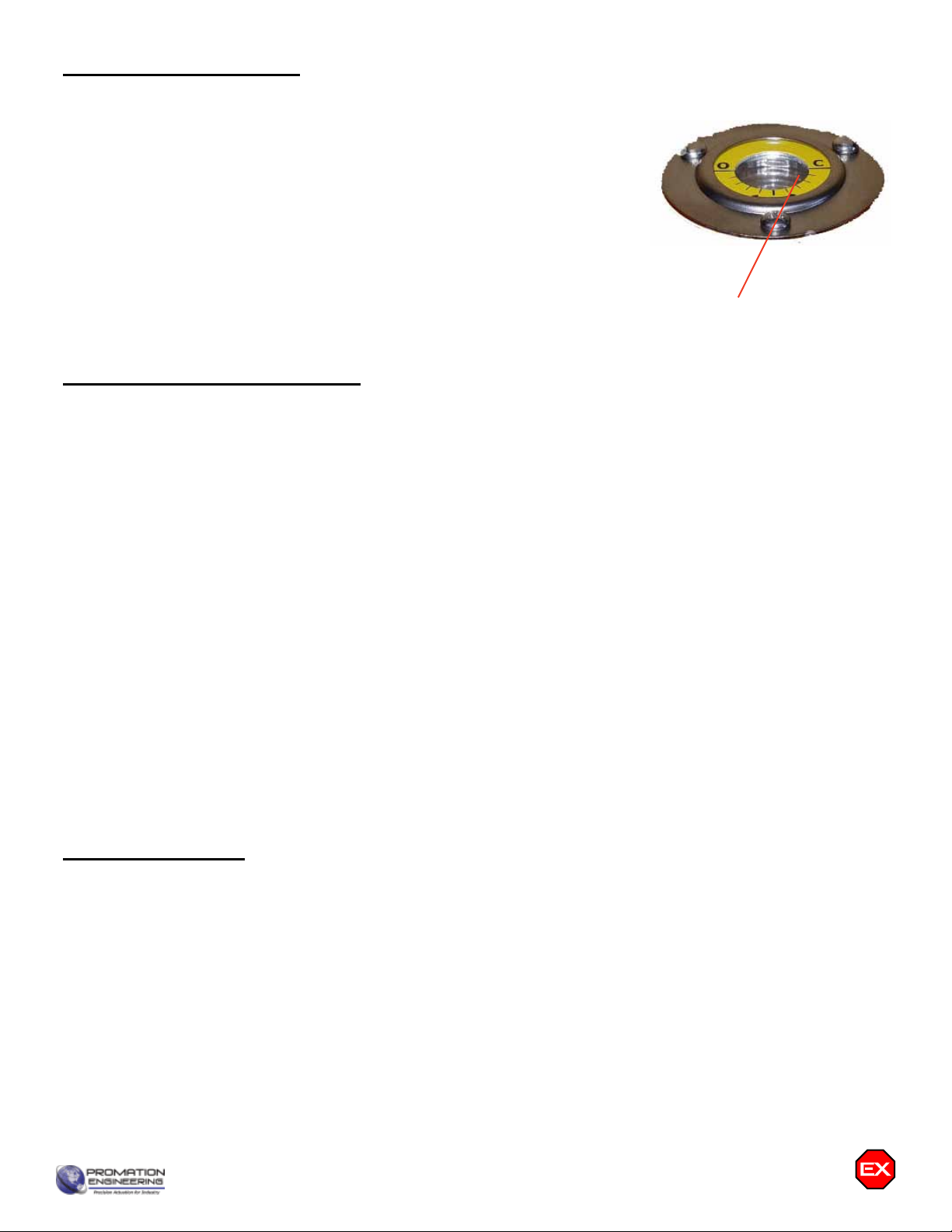
Position indicator
viewport
Easily distinguishable
yellow/red position
indicator
Heavy Duty
Drive Motor
Easily accessible
switch stack
Adjustable End of
Travel cams
(2) 1/2” EMT Ports
Switch Card
Anti-Condensation
Heater
Aluminum Casting
NEMA 4X Protection
Aluminum Casting
NEMA 4X Protection
NEMA 4X Cover Seal
Switch Logic Map and Switch/
Cam Arrangement
Switch sequencing data is provided in the table
below to show the change-of-state points during
the rotation of the actuator from CCW to CW
and back again. The red bar shows when that
terminal makes with its respective common.
Switches 1 and 2 are set at the factory and should
NOT be changed. The INCLUDED auxiliary
switches SW3 & SW4 are for terminals 7 thru 12
and those set points may be modied if need be.
SW3 CCW AUX
(Factory Set - Adj)
SW4 CW AUX
(Factory Set - Adj)
Used by
Controller
F
E
C
B
A
-5o0o
CW CCW
85o
5o90o95o
}
}
Common Switch Terminal
Open
Not Closed
Closed
Not Open
}
FM_PX1 LV N7 Ver B 072921
Page 10 of 11 P1 HV Series
Mechanical Data

This procedure will assume that the actuator is installed correctly both mechanically and electrically with correct power.
1. Apply the correct supply power to the actuator.
• NOTE - Power is measured at terminals marked 1 & 7 on the actuator.
1.A NORMAL OPERATION
I. Power applied to terminals marked 1 & 3 will cause the actuator to run CCW.
II. Power applied to terminals marked 1 & 4 will cause the actuator to run CW.
2. Test Full CW and CCW Positions
2.A Apply power to terminals marked 1 & 3
I. The actuator will drive to the full CCW position (as viewed from ABOVE the actuator).
II. If this is NOT the correct stop position, refer to Adjusting the actuator CCW position instructions for CAM 1 on
Page 5 in this document.
2.B Apply power to terminals marked 1 & 4
I. The actuator will drive to the full CW position (as viewed from ABOVE the actuator).
II. If this is NOT the correct stop position, refer to Adjusting the actuator CW position instructions for CAM 2 on
Page 5 in this document.
FM_PX1 LV N7 Ver B 072921
Page 11 of 11 P1 HV Series
Commissioning

This manual suits for next models
2
Table of contents
Other Promation Engineering Industrial Equipment manuals


Popular Industrial Equipment manuals by other brands


Fein
Fein GRIT GI 75 manual

Eaton
Eaton SL4-PIB Series Instruction leaflet

PCB Piezotronics
PCB Piezotronics IMI SENSORS 691M157 Installation and operating manual

Scheppach
Scheppach combi 6 Original instructions

Pfannenberg
Pfannenberg PWS Series Installation, operation and service manual

SIAM
SIAM SIDDOS-automat 3M Operation manual


